Advertisement
Available languages
Available languages
Quick Links
INSTRUCTION
EN
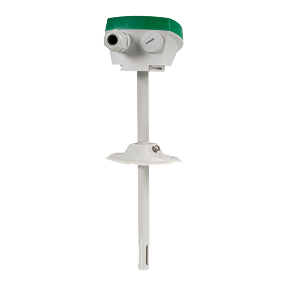
DTT(H)(C)
IN20046 REV. D, 2024-12-03
Caution! Read and understand the instruction before us-
ing the product.
Caution! Ensure that the installation complies with local
safety regulations.
Caution! Before installation or maintenance, the power
supply should first be disconnected. Installation or main-
tenance of this unit should only be carried out by qualified
personnel. The manufacturer is not responsible for any
eventual damage or injury caused by inadequate skills
during installation, or through removal of or deactivation
of any safety devices.
Function
The measurements received from DTT(H)(C) can be used to control
ventilation with high precision and improve the air quality in for
example residential and office areas. By increasing the air exchange only
when it is necessary, it is possible to minimise energy costs.
Technical Data
Supply voltage
24 V ~ (20...28 V ~ 50...60 Hz, 2 VA) / 15...35 V
DC
Power consumption
< 1.5 W
Load impedance, 0...10 V Min. 10 kΩ
Protection class
IP65 (housing)
Ambient humidity
0...90 % RH, non-condensing
Ambient temperature
-40...+60 °C
Storage temperature
-40...+80 °C
Max overvoltage
+10 V (referenced to GND)
Mounting
Duct
Insertion length
37...195 mm
Media
Air, non-combustible and non-aggressive gases
Measuring range,
-40...+60 °C
temperature
Output signal,
0...10 V (0 V = -40 °C, 10 V = 60 °C)
temperature
Accuracy, temperature
±0.2 K at 0...60 °C
Measuring range,
0...100 % RH
humidity
Output signal, humidity
0...10 V (0 V = 0 % RH, 10 V = 100 % RH)
Accuracy, humidity
±2 % RH at 25 °C, 10...90 % RH
Measuring range, CO
0...2000 ppm
2
Output signal, CO
0...10 V (0 V = 0 ppm, 10 V = 2000 ppm)
2
Accuracy, CO
±(50 ppm + 3 % of the measured value) at 25 °C
2
Temperature depend-
2.5 ppm/K at 0...50 °C
ency, CO
2
Cable gland
2 x M16
Cable connection
Screw terminals max. 1.5 mm
Warmup time
4 min
Diameter, probe
12 mm
Dimensions, external
104 x 211/212.5 x 79 mm
(WxHxD)
Weight (incl. packaging)
0.23 kg (DTTH) / 0.25 kg (DTTC/DTTHC)
Table 1 Response times
Article
Response time,
Response time,
temp
humidity
DTTH
<50 s
1
<50 s
1
DTTC
<50 s
1
-
DTTHC
<50 s
1
<50 s
1
1. At 3 m/s air speed
DTT(H)(C)
Installation
1. Find a location in the duct where the transmitter can be expected to
give a representative reading. It should be placed at least 4 duct
diameters from a bend or other obstacle, e.g. a damper, for minimal
turbulence.
2. Use a 13 mm drill bit to make a hole in duct
3. Twist the cover to access the terminals
4. Place the DTTC/DTTHC transmitter in the duct with the cable
glands perpendicular to the air flow direction. See Figure 1.
5. Connect the wires to the terminals according to the wiring diagram
in Figure 3
Note! Make sure to use a round cable and ensure that
the cable gland makes a tight seal around the cable.
You should also consider possible leakage inside a
short cable (such as, air in between conductors). Other-
wise you can have incorrect measurement values due
to intruding air.
6. After applying power to the transmitter, the time it takes to show
correct values is specified under Warm-up time in the technical data
table. A green LED, located under the cover, indicates when the
transmitter is ready to use (see Table 2).
7. Screw the cover back on and ensure that the cover is properly
fastened, and that the cable gland makes a tight seal around the cable
2
(AWG 16)
Figure 1 Installation direction in duct (A = air flow direction)
Caution! If there is a risk for condensation in the probe,
mount the transmitter upright.
Response time,
CO
2
-
<100 s
1
<100 s
1
A
1 (7)
Advertisement

Subscribe to Our Youtube Channel
Related Manuals for Regin DTT


Summary of Contents for Regin DTT
- Page 1 Caution! If there is a risk for condensation in the probe, mount the transmitter upright. Table 1 Response times The measurements received from DTT(H)(C) can be used to control ventilation with high precision and improve the air quality in for Article...
- Page 2 Funktion Figure 2 Mounting at condensation risk Mätningarna som erhålls från DTT(H)(C) kan användas för att styra LED indications ventilationen med hög precision och förbättra luftkvaliteten i exempelvis bostads- och kontorslokaler. Genom att endast öka luftutbytet när det är A LED light under the lid indicates the status of the transmitter, as nödvändigt är det möjligt att minimera energikostnaderna.
- Page 3 7. Skruva tillbaka locket och se till att det sitter fast ordentligt och att □ □ □ □ □ □ □ kabelgenomföringen sluter tätt runt kabeln. Figur 3 Inkopplingsschema Denna produkt är CE-märkt. Mer information finns på www. regincontrols.com. DTT(H)(C) 3 (7)
- Page 4 Gewicht (inkl. 0,23 kg (DTTH) / 0,25 kg (DTTC/DTTHC) Verpackung) Die von DTT(H)(C) erhaltenen Messwerte können eingesetzt werden, Bild 1 Einbaurichtung im Kanal (A = Volumenstromrichtung) um die Lüftung mit hoher Präzision zu regeln und die Luftqualität z.B. Tabelle 1 Reaktionszeiten in Wohn- und Büroräumen zu verbessern.
- Page 5 Sensorproblem. Fonction Verdrahtung Les mesures transmises par le DTT(H)(C) peuvent être utilisées pour Der Zugang zu den Klemmen erfolgt durch Drehen der Abdeckung. contrôler la ventilation avec une grande précision et améliorer la qualité Schließen Sie die Kabel gemäß dem unten stehenden Bild 3 Schaltbild de l'air, par exemple dans les zones résidentielles et les bureaux.
- Page 6 7. Revissez le couvercle et assurez-vous qu'il est bien fixé et que le Ce produit est marqué CE. Pour plus d’information, veuillez consulter presse-étoupe assure une bonne étanchéité autour du câble. Fig. 3 Schéma de raccordement www.regincontrols.fr. DTT(H)(C) 6 (7)
- Page 7 Contact Regin France, 32 rue Delizy, Hall 3, 93500 Pantin Tél. : +33(0)1 41 83 02 02, Fax : +33(0)1 57 14 95 91 www.regin.fr, info@regin.fr DTT(H)(C) 7 (7)
Need help?
Do you have a question about the DTT and is the answer not in the manual?
Questions and answers