Table of Contents
Advertisement
Available languages
Available languages
Quick Links
EN
INSTRUCTION
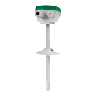
DTT(H)(C)
IN20046 REV. C, 2023-01-19
C C a a u u t t i i o o n n ! ! Read and understand the instruction before using the product.
C C a a u u t t i i o o n n ! ! Ensure that the installation complies with local safety
regulations.
C C a a u u t t i i o o n n ! ! Before installation or maintenance, the power supply should first
be disconnected. Installation or maintenance of this unit should only be
carried out by qualified personnel. The manufacturer is not responsible
for any eventual damage or injury caused by inadequate skills during instal-
lation, or through removal of or deactivation of any security devices.
Function
The measurements received from DTT(H)(C) can be used to control
ventilation with high precision and improve the air quality in for
example residential and office areas. By increasing the air exchange only
when it is necessary, it is possible to minimise energy costs.
Technical Data
Supply voltage
24 V ~ (20...28 V ~ 50...60 Hz, 2 VA) / 15...35 V
DC
Power consumption
< 1.5 W
Load impedance, 0...10 V Min. 10 kΩ
Protection class
IP65 (housing)
Ambient humidity
0...90 % RH, non-condensing
Ambient temperature
-40...+60 °C
Storage temperature
-40...+80 °C
Max overvoltage
+10 V (referenced to GND)
Mounting
Duct
Insertion length
37...195 mm
Media
Air, non-combustible and non-aggressive gases
Measuring range,
-40...+60 °C
temperature
Output signal,
0...10 V (0 V = -40 °C, 10 V = 60 °C)
temperature
Accuracy, temperature
±0.2 K at 0...60 °C
Measuring range,
0...100 % RH
humidity
Output signal, humidity
0...10 V (0 V = 0 % RH, 10 V = 100 % RH)
Accuracy, humidity
±2 % RH at 25 °C, 10...90 % RH
Measuring range, CO
0...2000 ppm
2
Output signal, CO
0...10 V (0 V = 0 ppm, 10 V = 2000 ppm)
2
Accuracy, CO
±(50 ppm + 3 % of the measured value) at 25 °C
2
Temperature depend-
2.5 ppm/K at 0...50 °C
ency, CO
2
Cable gland
2 x M16
Cable connection
Screw terminals max. 1.5 mm
Warmup time
4 min
Diameter, probe
12 mm
Dimensions, external
104 x 211/212.5 x 79 mm
(WxHxD)
Weight (incl. packaging)
0.23 kg (DTTH) / 0.25 kg (DTTC/DTTHC)
Table 1 Response times
Article
Response time,
Response time,
temp
humidity
DTTH
<50 s
1
<50 s
1
DTTC
<50 s
1
-
DTTHC
<50 s
1
<50 s
1
1. At 3 m/s air speed
– Find a location in the duct where the transmitter can be expected to
give a representative reading. It should be placed at least 4 duct
diameters from a bend or other obstacle, e.g. a damper, for minimal
turbulence.
DTT(H)(C)
– Use a 13 mm drill bit to make a hole in duct
– Twist the cover to access the terminals
– Place the DTTC/DTTHC transmitter in the duct with the cable
glands perpendicular to the air flow direction, see Figure 1.
– Connect the wires to the terminals according to the wiring diagram
in Figure 2
– After applying power to the transmitter, the time it takes to show
correct values is specified under Warmup time in the technical data
table. A green LED, located under the cover, indicates when the
transmitter is ready to use (see Table 2).
– Screw the cover back on and ensure that it is properly fastened and
that the cable gland makes a tight seal around the cable.
N N o o t t e e ! ! If there is a risk for condensation in the probe, mount the transmit-
ter upright.
Figure 1 Installation direction in duct (A = air flow direction)
2
(AWG 16)
LED indications
A LED light under the lid indicates the status of the transmitter as
shown in Table 2.
Table 2 LED status indications
LED indications
Green, solid
Red, solid
Response time,
CO
2
-
Wiring
<100 s
1
The terminals are accessed by twisting the cover. Connect the cables
<100 s
1
according to the wiring diagram below.
Ɵ Ɵ Ɵ Ɵ Ɵ Ɵ Ɵ
□ □ □ □ □ □ □
Figure 2 Wiring diagram
A
Description
Power is on. All is OK.
Sensor problem.
1 (6)
Advertisement
Table of Contents

Subscribe to Our Youtube Channel
Related Manuals for Regin DTTH


Summary of Contents for Regin DTTH
- Page 1 104 x 211/212.5 x 79 mm lation, or through removal of or deactivation of any security devices. (WxHxD) Table 2 LED status indications Weight (incl. packaging) 0.23 kg (DTTH) / 0.25 kg (DTTC/DTTHC) LED indications Description Function Green, solid Power is on. All is OK.
- Page 2 0…10 V (0 V = -40 °C, 10 V = 60 °C) Supply voltage Noggrannhet, temperatur ±0,2 K vid 0…60 °C AB Regin, Box 116, 428 22 Kållered, Sweden Tel: +46 31 720 02 00, Fax: +46 31 720 02 50 System neutral Mätområde, fukt...
- Page 3 Figur 2 Inkopplingsschema Medien Luft, nicht brennbare und nicht aggressive Gase Kontakt Messbereich, Temperatur -40…+60 °C AB Regin, Box 116, 428 22 Kållered, Sverige Plint Beskrivning Ausgangssignal, 0…10 V (0 V = -40 °C, 10 V = 60 °C) Tel: +46 31 720 02 00, Fax: +46 31 720 02 50 Matningsspänning...
- Page 4 Kontakt Bild 2. Masse – Die Zeit, die der Transmitter nach dem Anlegen der Spannung Regin Controls Deutschland GmbH, Haynauer Str. 49, 12249 Berlin, benötigt, um korrekte Werte anzuzeigen, ist in der Tabelle der Temperaturausgang Deutschland technischen Daten unter Aufwärmzeit angegeben. Eine grüne LED, Tel.: +49 30 77994-0, Fax: +49 30 77994-79...
- Page 5 (L x H x P) Fig. 1 Sens d'installation dans la gaine (A = sens de l'écoulement d'air) Fonction Poids (emballage inclus) 0,23 kg (DTTH)/0,25 kg (DTTC/DTTHC) Voyant d'indications Les mesures transmises par le DTT(H)(C) peuvent être utilisées pour Un voyant placé sous le couvercle indique l'état du transmetteur tel contrôler la ventilation avec une grande précision et améliorer la qualité...
- Page 6 B = élément sensible de CO Ce produit est marqué CE. Pour plus d’information, veuillez consulter www.regincontrols.fr Contact Regin France, 32 rue Delizy, Hall 3, 93500 Pantin Tél. : +33(0)1 41 83 02 02, Fax : +33(0)1 57 14 95 91 www.regin.fr, info@regin.fr DTT(H)(C)
Need help?
Do you have a question about the DTTH and is the answer not in the manual?
Questions and answers