Advertisement
Quick Links
Advertisement

Related Manuals for Pipelife FLOORTHERM Thermostat s


Summary of Contents for Pipelife FLOORTHERM Thermostat s
- Page 1 PIPELIFE FLOORTHERM Thermostat s...
-
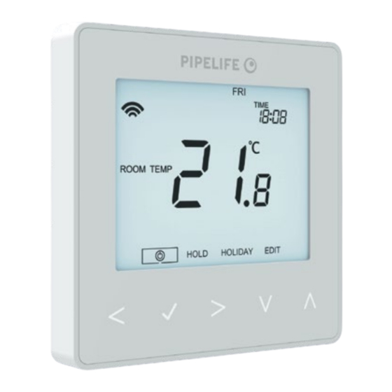
Page 2: Product Image
Thermostat s Model: PIPELIFE FLOORTHERM... -
Page 3: Table Of Contents
Table of Contents Product Image Frost Mode Table of Contents Power ON/OFF What is a Programmable Holiday Room Thermostat Optional Settings 23-26 Installation Procedure Re-calibrating the Thermostat Mode Select Error Codes Pairing with the Router Floor Temp Sensor Probe Type Pairing the thermostat Wiring Diagrams 29-32... -
Page 4: What Is A Programmable
Similarly reducing the temperature setting does not affect how quickly the room cools down. Setting a programmable room thermostat to a lower temperature will result in the room being controlled at a lower temperature, and saves energy. PIPELIFE FLOORTHERM... - Page 5 The way to set and use your programmable room thermostat is to find the lowest temperature settings that you are comfortable with at the different times you have chosen, and then leave it alone to do its job. The best way to do this is to set the room thermostat to a low temperature –...
-
Page 6: Installation Procedure
Note: For time clock wiring connections, terminate as shown on page 39. Step 3 Screw the thermostat back plate securely into the back box. Step 4 Clip the front of the thermostat onto the back plate, securing it in place with the retaining screw. PIPELIFE FLOORTHERM... - Page 7 Thermostat s...
-
Page 8: Mode Select
• Press the Tick key to confirm selection ................The thermostat will revert to the main display screen for the selected mode. For time clock mode instructions, first pair the time clock with the Router as explained on page 8, then turn to page 34. PIPELIFE FLOORTHERM... -
Page 9: Pairing With The Router
Pairing with the Router • Connect the ‘Pipelife Floortherm Router’ to your broadband router using the ethernet cable provided. Connect the power supply also provided • with the ‘Pipelife Floortherm Router’. Download the Pipelife app and register your • account. Sign in to your account, select the ‘Add Router’... -
Page 10: What Is A Mesh Network
The Thermostat s uses proximity to detect when you are about to use the touch keys. As you approach the thermostat, the touch keys and backlight will light up. This can be useful if you need to adjust the set temp or timer in a dark room. PIPELIFE FLOORTHERM... -
Page 11: Mode 1 - Thermostat
Mode 1 - Thermostat Thermostat s... - Page 12 PIPELIFE FLOORTHERM...
-
Page 13: Lcd Display
LCD Display 1. Mesh Symbol - Displayed when connected to the Router. 2. Day Indicator - Displays the day of the week. 3. Frost Protection – Displayed when frost protection is enabled. 4. Flame Symbol – Displayed when the thermostat is calling for heat and flashes when optimum start is active. -
Page 14: Temperature Display
When the thermostat is set to use both the air & the floor sensor, the room temperature will be displayed by default. To view the current floor temperature, press and hold the Left and Right arrow keys for 5 seconds, the floor temperature will then be displayed ....PIPELIFE FLOORTHERM... -
Page 15: Setting The Clock
Setting the Clock To set the clock, follow these steps. • Use the Left / Right keys to scroll to ..............• Press and hold Tick to turn off the display ..............• Use the right arrow key to select CLOCK ............... •... -
Page 16: Setting The Comfort Levels
Use the Left / Right keys to select day / period of week (the selection will flash).. • Press Tick to confirm selection ....................• WAKE will now flash and the current time and temperature setting will be shown. • Press Tick to alter WAKE settings ....................• PIPELIFE FLOORTHERM... - Page 17 Use the Up / Down keys to set the hours ............ • Press Tick to confirm ......................• Use the Up / Down keys to set the minutes ..........• Press Tick to confirm ....................... • Use the Up / Down keys to set the temperature ......... •...
-
Page 18: Temperature Control
Press Tick to confirm settings and return to the main display ........Set Temperature Set Icon Note: This new temperature is maintained only until the next programmed comfort level. At this time, the thermostat will revert back to the programmed levels. PIPELIFE FLOORTHERM... -
Page 19: Temperature Hold
Temperature Hold The temperature hold function allows you to manually override the current operating program and set a di erent temperature for a desired period. • Use the Left / Right keys to scroll to HOLD............• Press Tick to confirm selection ..................•... -
Page 20: Locking/Unlocking The Thermostat
Use the Up / Down and keys to enter the first two digits ....• Use the Up / Down and keys to enter the second two digits ..• The display will unlock and return to the main screen. PIPELIFE FLOORTHERM... -
Page 21: Frost Mode
Frost Mode Use the Left / Right keys to scroll to the Power Icon ........The frost icon will toggle ON/OFF each time Tick is pressed ......... In this mode, the stat will display the frost icon and will only turn the heating ON should the room temperature drop below the set frost temperature (see page 23). -
Page 22: Power On/Off
Tick key for approximately 3 seconds until the display goes blank ..The display and heating output will be turned OFF. To turn the thermostat back ON, press the Tick key once ............Thermostat completely OFF Thermostat powered ON PIPELIFE FLOORTHERM... -
Page 23: Holiday
Holiday In thermostat mode, the holiday function reduces the set temperature in your home to the frost protection temperature setting (see page 23). The thermostat will maintain this temperature for the duration of the holiday and will then automatically return to the program mode on your return. In time clock mode, the holiday function maintains the timed output as OFF. -
Page 24: Optional Settings
NEED NOT BE ADJUSTED Feature 01 – Pairing To The Router: This function is used to pair the thermostat to the Pipelife Floortherm Router. Feature 02 - Switching Differential: This function allows you to increase the switching differential of the thermostat. The default is 1°C, which means that with a set temperature of 20°C, the thermostat will switch the heating on at 19°C and off... - Page 25 Optimum start will delay the start-up of the heating Feature 08 – Optimum Start: system to the latest possible moment to avoid unnecessary heating and ensure the building is warm at the programmed time. The thermostat uses the rate of change information to calculate how long the heating needs to raise the building temperature 1°C (with a rate of change of 20, the thermostat has calculated the heating needs 20 minutes to raise the building temperature 1°C) and starts the...
-
Page 26: Adjusting The Optional Settings
Use the Up/Down keys to select the feature you would like to adjust..• Use the Left / Right keys to adjust the setting within the feature..• Press to confirm settings and exit the setup menu ....... PIPELIFE FLOORTHERM... - Page 27 Optional Settings - Feature Table FEATURE DESCRIPTION SETTING Pairing Used to add zone to the Router Switching Differential 00.5 = 0.5°C 01 = 1.0°C (Default) 02 = 2.0°C 03 = 3.0°C Frost Protection Temperature 07° - 17°C (12°C = Default) Output Delay 00 - 15 Minutes (00 = Default) Up/Down Temperature Limit...
-
Page 28: Re-Calibrating The Thermostat
The remote FLOOR probe has not been wired correctly. The remote FLOOR probe is faulty. E2 = The remote AIR probe has not been connected. The remote AIR probe has not been wired correctly. The remote AIR probe is faulty. PIPELIFE FLOORTHERM... -
Page 29: Floor Temp Sensor Probe Type
Floor Temperature Sensor ProbeType This thermostat is configured by default for compatibility with 10K sensor probes. The thermostat is also compatible with two other common probe values which are 12K or 15K. To change the probe type, follow these steps; •... -
Page 30: Wiring Diagram
Thermostat s 230VAC TO CONNECT BOILER CONSULT BOILER MAKERS DIAGRAM A2 A1 LIVE 230V SUPPLY IN NEUTRAL SWITCHED LIVE TO BOILER This product must only be installed by a quali ed electrician and comply with local installation regulations. PIPELIFE FLOORTHERM... - Page 31 Wiring Diagram - Thermostat to Boiler Voltfree Thermostat s 230VAC TO CONNECT BOILER CONSULT A2 A1 BOILER MAKERS DIAGRAM VOLT FREE TO BOILER LIVE 230V SUPPLY IN LS & LR ARE NORMALLY THE NEUTRAL ROOM THERMOSTAT CONNECTIONS This product must only be installed by a quali ed electrician and comply with local installation regulations.
- Page 32 BOILER MAKERS DIAGRAM LIVE 230V SUPPLY IN NEUTRAL TO BOILER NEUTRAL LS & LR ARE NORMALLY THE HEATING VALVE ROOM THERMOSTAT CONNECTIONS This product must only be installed by a quali ed electrician and comply with local installation regulations. PIPELIFE FLOORTHERM...
-
Page 33: Wiring Diagrams
Wiring Diagram Thermostat to Hub8 and Optional Remote Probe Connections Thermostat s 230VAC A2 A1 FLOOR PROBE (Optional) REMOTE AIR PROBE (Optional) This product must only be installed by a quali ed electrician and comply with local installation regulations. Thermostat s... -
Page 34: Factory Reset
The thermostat will revert to the main display screen for the selected mode. Note: Factory reset will cancel all parameters that were entered during the set-up and pairing operations. These processes must be repeated after factory reset is completed. PIPELIFE FLOORTHERM... -
Page 35: Mode 2 - Time Clock
Mode 2 - Time Clock Thermostat s... -
Page 36: Lcd Display
Timer Status – Displays the current state of the timed output. Hold Left - Displayed when a timer hold is active, the remaining time will be shown. Time/Day/Month/Year - Displays when setting the Clock/Calendar or a Holiday Period. PIPELIFE FLOORTHERM... -
Page 37: Setting The Switching Times
Setting the Switching Times To program the switching times, follow these steps. • Use the Left / Right keys to scroll to EDIT and press Tick ....• Use the Left / Right keys to select day/period of the week ...... •... -
Page 38: Timer Override
• Use the Up / Down keys to set the override duration e.g. 02:00 hours ..• Press Tick to confirm settings and return to main display ........Hold Left and the remaining time will now be displayed. HOLD LEFT Indicator Hold Time Remaining PIPELIFE FLOORTHERM... -
Page 39: Optional Features
Optional Features Explained Feature 01 – Pairing To Router: This function is used to connect the time clock to the Router. Feature 02 - Weekday/Weekend (5/2), 7 Day Programming or 24 Hour Mode: The time clock offers three programming methods; Weekday/ Weekend (5/2) - Allows you to program 4 on/off... -
Page 40: Time Clock Mode Wiring Diagram
RT2 RT1 A2 A1 VOLT FREE OUTPUT LIVE 230V SUPPLY IN NEUTRAL FOR 230V OUTPUT ON A2 LINK LIVE TO A1 This product must only be installed by a quali ed electrician and comply with local installation regulations. PIPELIFE FLOORTHERM... - Page 41 Notes ..................................................................................................................................................................................................................................................................................................................................................................................................................................................... Thermostat s...
- Page 42 Notes ..................................................................................................................................................................................................................................................................................................................................................................................................................................................... PIPELIFE FLOORTHERM Model: Manual REF...
- Page 43 Notes ..................................................................................................................................................................................................................................................................................................................................................................................................................................................... Thermostat s...
- Page 44 PIPELIFE International GmbH, Wienerbergerplatz 1, 1100 Wien T +43 1 602 2030 0, E info@pipelife.com, pipelife.com Rev.1.0...
Need help?
Do you have a question about the FLOORTHERM Thermostat s and is the answer not in the manual?
Questions and answers