Advertisement
Quick Links
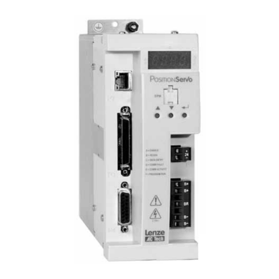
AC Tech E94P040Y2NEM
940 PositionServo with MVOB
A l l t r a d e m a r k s , b r a n d n a m e s , a n d b r a n d s a p p e a r i n g h e r e i n a r e t h e p r o p e r t y o f t h e i r r e s p e c t i v e o w n e r s .
• C r i t i c a l a n d e x p e d i t e d s e r v i c e s
• I n s t o c k / R e a d y - t o - s h i p
Artisan Scientific Corporation dba Artisan Technology Group is not an affiliate, representative, or authorized distributor for any manufacturer listed herein.
Limited Availability
Used and in Good Condition
Open Web Page
https://www.artisantg.com/83819-1
• We b u y y o u r e x c e s s , u n d e r u t i l i z e d , a n d i d l e e q u i p me n t
• F u l l - s e r v i c e , i n d e p e n d e n t r e p a i r c e n t e r
Advertisement

Related Manuals for Lenze AC Tech E94P040Y2NEM

Summary of Contents for Lenze AC Tech E94P040Y2NEM
- Page 1 AC Tech E94P040Y2NEM 940 PositionServo with MVOB Limited Availability Used and in Good Condition Open Web Page https://www.artisantg.com/83819-1 A l l t r a d e m a r k s , b r a n d n a m e s , a n d b r a n d s a p p e a r i n g h e r e i n a r e t h e p r o p e r t y o f t h e i r r e s p e c t i v e o w n e r s .
- Page 2 PositionServo with MVOB Users Manual...
- Page 3 Copyright ©2008 by AC Technology Corporation. All rights reserved. No part of this manual may be reproduced or transmitted in any form without written permission from AC Technology Corporation. The information and technical data in this manual are subject to change without notice. AC Tech makes no warranty of any kind with respect to this material, including, but not limited to, the implied warranties of its merchantability and fitness for a given purpose.
- Page 4 Contents Introduction..........5 Safety Information .
- Page 5 Contents Communication Interfaces ......... .39 4.4.1 Ethernet Interface (standard) .
- Page 6 Contents Velocity Limits ...........58 5.7.1 Zero Speed.
- Page 7 About These Instructions This documentation pertains to the PositionServo drive and contains important technical data regarding the installation, operation and commissioning of the drive. Observe all safety instructions. Read this document in its entirety before operating or servicing a PositionServo drive. Drive Identification Label INPUT: 1(3)/PE OUTPUT: 3/PE...
- Page 8 Introduction Introduction Safety Information The safety information provided in this documentation has the layout shown herein. Signal Word! (Characteristics the severity of the danger) Note (describes the danger and informs on how to proceed) Table 2: Pictographs used in these Instructions Signal Words Icon DANGER!
- Page 9 Introduction Claim Description Application as Drive systems with E94P or E94R servo inverters directed • comply with the EMC Directive if they are installed according to the guidelines of CE- typical drive systems. • can be used for: - for operation on public and non-public mains - for operation in industrial premises and residential areas.
- Page 10 Introduction 1.3.2 Operating Modes The PositionServo drive can operate in one of three mode settings, torque (current), velocity, or positioning. The drive’s command or reference signal can come from one of three sources. The first is an external reference. An external reference can be an analog input signal, a step and direction input or an input from a master encoder.
- Page 11 Introduction Part Number Designation The table herein describes the part number designation for the PositionServo drive. The available filter and communication options are detailed in separate tables. 1.4.1 Drive Part Number Electrical Products in the 94x Series P = PositionServo Model 940 with Encoder Feedback R = PositionServo Model 941 with Resolver Feedback Drive Rating in Amps: 020 = 2 Amps...
- Page 12 Introduction 1.4.3 Option Part Number E94Z Electrical Option in the 94x Series A = COMM, Feedback or Breakout Module Module Type: Communication: Feedback or Breakout: CAN = CANopen COMM Module ENC = 2nd Encoder Feedback Module RS4 = RS485 COMM Module RSV = Resolver Feedback Module DVN = DeviceNet COMM Module HBK = Motor Brake Terminal Module...
- Page 13 Technical Data Technical Data Electrical Characteristics Single-Phase Models 1~ Mains 1~ Mains Rated Peak Type Mains Voltage Current Current Output Output (doubler) (Std.) Current Current E94_020S1N_~ 120V (3) or 240V (4) E94_040S1N_~ E94_020S2F_~ E94_040S2F_~ 120 / 240V (80 V -0%...264 V +0%) E94_080S2F_~ 15.0 E94_100S2F_~...
- Page 14 Technical Data Electrical Specifications applicable to all models: Acceleration Time Range (Zero to Max Speed) 0.1 … 5x10 RPM/sec Deceleration Time Range (Max Speed to Zero) 0.1 … 5x10 RPM/sec Speed Regulation (typical) ± 1 RPM Input Impedance (AIN+ to COM and AIN+ to AIN-) 47 kΩ...
- Page 15 Technical Data Fuse Recommendations AC Line AC Line Miniature Input Fuse or DC Bus Input Type Input Fuse Circuit Breaker Breaker Fuse (5) (6) (1ø/3ø) (1ø/3ø) (N. America) Amp Ratings E94_020S1N_~ M20/M10 C20/C10 20/10 E94_040S1N_~ M32/M20 C32/C20 30/20 E94_020S2F_~ E94_040S2F_~ E94_080S2F_~ E94_100S2F_~ E94_020Y2N_~...
- Page 16 Technical Data Environment Vibration 2 g (10 - 2000 Hz) Ambient Operating Temperature Range 0 to 40ºC Ambient Storage Temperature Range -10 to 70ºC Temperature Drift 0.1% per ºC rise Humidity 5 - 90% non-condensing Altitude 1500m/5000ft [derate by 1% per 300m (1000 ft) above 1500m (5000 ft)] Operating Modes Torque...
- Page 17 Technical Data PositionServo Dimensions dia = 4.57 4.57 S923 Type A (mm) B (mm) C (mm) D (mm) Weight (kg) E94_020S1N_X E94_040S1N_X E94_020S2F_X E94_040S2F_X E94_080S2F_X E94_100S2F_X E94_020Y2N_X E94_040Y2N_X E94_080Y2N_X E94_100Y2N_X E94_120Y2N_X E94_180T2N_X E94_020T4N_X E94_040T4N_X E94_050T4N_X E94_060T4N_X E94_090T4N_X The first “_” equals “P” for the Model 940 encoder based drive or “R” for the Model 941 resolver based drive. The second “_”...
- Page 18 Technical Data Dimensions for Coldplate Drives S974 Type A (mm) B (mm) C (mm) D (mm) Weight (kg) E94_120Y2C~_ E94_180T2C~_ E94_060T4C~_ E94_090T4C~_ The first “_” equals “P” for the Model 940 encoder based drive or “R” for the Model 941 resolver based drive. The 10th digit is marked by “C”...
- Page 19 Installation Installation Perform the minimum system connection. Refer to section 6.1 for minimum connection requirements. Observe the rules and warnings below carefully: DANGER! Hazard of electrical shock! Circuit potentials are up to 480 VAC above earth ground. Avoid direct contact with the printed circuit board or with circuit elements to prevent the risk of serious injury or fatality.
- Page 20 Installation Wiring DANGER! Hazard of electrical shock! Circuit potentials are up to 480 VAC above earth ground. Avoid direct contact with the printed circuit board or with circuit elements to prevent the risk of serious injury or fatality. Disconnect incoming power and wait 60 seconds before servicing the drive.
- Page 21 Installation Compliance with EN 61800-3:2004 In a domestic environment this product may cause radio interference. The user may be required to take adequate measures Noise emission Installation according to EMC Requirements Drive Models ending in the suffix “2F” are in compliance with class A limits according to EN 55011 if installed in a control cabinet and the motor cable length does not exceed 10m.
- Page 22 Installation NOTE The ground connection from the filter must be wired to solid earth ground, not machine ground. If the end-user is using a CE-approved motor, the AC filter combined with the recommended motor and encoder feedback cables, is all that is necessary to meet the EMC directives listed herein.
- Page 23 Interface Interface The standard PositionServo drive is equipped with seven connectors including: four quick-connect terminal blocks, one SCSI connector, one subminiature type “D” connector and one ethernet RJ45 connector. These connectors provide communications from a PLC or host controller, power to the drive, and feedback from the motor. Prefabricated cable assemblies may be purchased from Lenze to facilitate wiring the drive, motor and host computer.
- Page 24 Interface All conductors must be enclosed in one shield with a jacket around them. The shield on the drive end of the motor power cable should be terminated to the conductive machine panel using screen clamps as shown in section 3.2. The other end should be properly terminated at the motor shield.
- Page 25 Interface 4.1.3 P3 - Controller I/O P3 is a 50-pin SCSI connector to interface with the front-end of the controller. It is strongly recommended that OEM cables be used to aid in satisfying CE requirements. Contact your Lenze representative for assistance. P3 Pin Assignments (Controller Interface) Name Function...
- Page 26 Interface 4.1.4 P4 - Motor Feedback For encoder-based 940 drives, P4 is a 15-pin DB connector that contains connections for an incremental encoder with Hall emulation tracks or Hall sensors. For synchronous servo motors, Hall sensors or Hall emulation tracks are necessary for commutation. If an asynchronous servo motor is used, it is not necessary to connect Hall sensor inputs.
- Page 27 Interface P4A Pin Assignments (Encoder Feedback - E94P Drives) Name Function Encoder Channel A+ Input Encoder Channel A- Input Encoder Channel B+ Input Encoder Channel B- Input Encoder Channel Z+ Input Encoder Channel Z- Input Drive Logic Common/Encoder Ground SHLD Shield Encoder supply (+5VDC) Hall Sensor A- Input...
- Page 28 Interface 4.1.6 P6 - Braking Resistor and DC Bus P6 is a 5-pin quick-connect terminal block that can be used with an external braking resistor (the PositionServo has the regen circuitry built-in). The Brake Resistor connects between the Positive DC Bus (either P6.1 or 2) and P6.3. P6 Terminal Assignments (Brake Resistor and DC Bus) Terminal Function...
- Page 29 Interface Wiring the ENABLE Switch: P n 26 N A COM Pin 29 IN A3 P n 5 GND Pin 6 +5V Power Supply Pin 26 IN A COM Pin 29 IN A3 4.1.8 P11 - Resolver Interface Module (option module) PositionServo drives can operate motors equipped with resolvers from either the (P4) connection, for a resolver-based (E94R) drive, or from the Resolver option module for an encoder-based (E94P) drive.
- Page 30 Interface SW1 DIP Switch Settings Dip Switch SW1 PPR prequadrature Position 1 Position 2 Position 3 Position 4 Hardware/Software Hardware/Software Revision 1A10, 1A11, Revision 1C12 and 1B11, 1C11 higher 1024 (default) 1000 1000 1024 (default) 1024 (default) 2000 2000 2048 2048 2500 2500...
- Page 31 Interface P11 Pin Assignments (Resolver Feedback Option Module) Name Function Ref + Resolver reference connection Ref - No Connection Cos+ Resolver Cosine connections Cos- Sin+ Resolver Sine connections Sin- PTC+ Motor PTC Temperature Sensor PTC- STOP! Use only 10 V (peak to peak) or less resolvers. Use of higher voltage resolvers may result in feedback failure and damage to the resolver option module.
- Page 32 Interface 4.1.10 P8 - ISO 13849-1 Safety Circuit (option) If installed, the ISO 13849-1 Safety Circuit connector, P8, is located on the bottom of the PositionServo. P8, a 6-pin quick-connect terminal block. P8 Pin Assignments (ISO 13849-1 Safety Function) Name Function Bypass Voltage ISO 13849-1Bypass Voltage (+24VDC)
- Page 33 Interface WARNING! It is required that all information contained within this ISO 13849-1 standard be observed when implementing any part of this safety circuit functionality with the PositionServo drive. Operation of the EN954 Safety Circuit ISO 13849-1 Cat 3, PL d designates that the enable function of the drive be designed in such a way that a single fault in any of the parts of this enable circuit cannot lead to a loss of this safety function.
- Page 34 Interface Installation and Connection Connection of Two Safety Circuits with External +24V Supply Name Function Bypass ISO 13849-1 Bypass Voltage (+24VDC) Voltage External Bypass COM ISO 13849-1 Bypass Common +24VDC Safety Status ISO 13849-1 Safety Status Safety Circuit Input 1 Safety Input1 ISO 13849-1 Safety Input 1 (+24VDC to Enable) Safety Circuit...
- Page 35 Interface Setting up the Drive in a Maintenance Mode: WARNING! During test of the ISO 13849-1 circuit, as laid out in this documentation the drive will go to run (enabled) condition and motion from the motor may be generated. It is the responsibility of the system designer to ensure the system remains in a safe condition during the enclosed maintenance procedure.
- Page 36 Interface The following truth table shows logical conditions for ISO 13849-1 circuits. Safety Input 1 Safety Input 2 Safety Status Output Drive Display F_EF F_EF F_EF *1 – Drive display will change to condition shown on enable of the drive (Input A3 Enable) Place Input A3, hardware enable in the deactivated state.
- Page 37 Interface Electrical Characteristics Safety Input1, Safety Input2 and Safety Status are fully isolated from the rest of the drive circuits as shown in the following diagram. Safety Inputs Insulated, compatible with single-ended output (+24VDC) Enable voltage range: 18 to 30VDC Disable voltage range: 0 to 1.0 VDC Input Impedance 6.8 kΩ...
- Page 38 Interface Digital I/O Details 4.2.1 Step & Direction / Master Encoder Inputs (P3, pins 1-4) A master encoder with quadrature outputs or a step and direction pair of signals can be connected to the PositionServo to control position in the external positioning operating mode.
- Page 39 Interface 4.2.2 Buffered Encoder Output (P3, pins 7-12) There are many applications where it is desired to close the feedback loop to an external device. This feature is built into the PositionServo drive and is referred to as the “Buffer Encoder Output”.
- Page 40 Interface 4.2.4 Digital Inputs IN_Ax, IN_Bx, IN_Cx (P3.26-30, P3.31-35, P3.36-40) The PositionServo drive has 12 optically isolated inputs. These inputs are compatible with a 5 - 24V voltage source. No additional series resistors are needed for circuit operation. The 12 inputs are segmented into three groups of 4, Inputs A1 - A4, Inputs B1 - B4, and Inputs C1 - C4.
- Page 41 Interface Analog I/O Details 4.3.1 Analog Reference Input AIN1+, AIN1- (P3.24 and P3.25) The analog reference input can accept up to a ±10V analog signal across AIN1+ and AIN1-. The maximum limit with respect to analog common (ACOM) on each input is ±18VDC.
- Page 42 Interface 4.3.2 Analog Output AO (P3.23) The analog output is a single-ended signal (with reference to Analog Common (ACOM) which can represent the following motor data: • Not Assigned • Phase R Current • Iq Current • RMS Phase Current •...
- Page 43 Interface 4.4.3 Modbus RTU Support The RS485 interface is configured through the MotionView program. When configured for Modbus operation, the baud rate for RS485 is set using the parameter “RS485 baud rate”. Modbus RTU requires 8 data bits. The Modbus RTU slave interface protocol definitions can be found on the MotionView CD in “Product Manuals”, P94MOD01.
- Page 44 Interface 4.4.6 PROFIBUS DP Interface An optional PROFIBUS DP communication module (E94ZAPFB1) is available for the PositionServo drive. Installed in Option Bay 1 as P24, the PROFIBUS DP module is optically isolated from the rest of the drive’s circuitry. The PROFIBUS module is a female DB-9 connector.
- Page 45 Parameters Parameters The drive has many programmable features and parameters accessible via a universal software called MotionView. This chapter covers the PositionServo’s programmable features and parameters in the order they appear in the Parameter Tree of MotionView. Programmable parameters are divided into folders. Each folder holds one or more user adjustable parameters.
- Page 46 Parameters Drive name: E94P 240V 04Amp Drive IP address: 192.168.124.120 Indexer program status: STOPPED (indexer program is stopped) RUNNING (indexer program is running) The drive identifier also indicates the status of the drive. When the drive identifier in the node tree is highlighted in green, the drive is enabled. When the drive identifier is gray, the drive is disabled.
- Page 47 Parameters To make a new motor selection: • Click [Change Motor] in the Parameter View Window. • Select motor Vendor and Motor Model from the pull down menus. • Click [Update Drive] to complete the motor selection, dismiss the dialog box and return to MotionView OnBoard’s main program.
- Page 48 Parameters • To load this file to the drive, click [Update Drive]. • When selecting [OK] for a custom motor, a dialog box will appear prompting for a decision to perform/not perform “Autophasing” (refer to section 5.2.4). 5.2.3 Creating Custom Motor Parameters STOP! Use extreme caution when entering custom parameters! Incorrect settings may damage the drive or motor! If unsure of the settings,...
- Page 49 Parameters To perform autophasing: Complete the steps in “Creating custom motor parameters”. If the motor file to be autophased already exists, simply load it as described under “Using a custom motor”. Make sure that the motor’s shaft is not connected to any mechanical load and can freely rotate.
- Page 50 Parameters 5.2.5.1 Electrical & Mechanical Constants Motor Torque Constant (Kt) Enter the value and select proper units from the drop-down list. NOTE Round the calculated result to 3 significant places. Motor Voltage Constant (Ke) The program expects Ke to be entered as a phase-to-phase Peak voltage. If you have Ke as an RMS value, multiply this value by 1.414 for the correct Ke Peak value.
- Page 51 Parameters Nominal Bus Voltage (Vbus) The Nominal Bus Voltage can be calculated by multiplying the Nominal AC mains voltage supplied by 1.41. When using a model with the suffix “S1N” where the mains are wired to the “Doubler” connection, the Nominal Bus Voltage will be doubled.
- Page 52 Parameters Look at the “Vst” Output Voltage. Determine which Hall Voltage is in phase with this Voltage. Per Figure S912, the Hall C output is in phase with the Vst Output Voltage. Look at the “Vtr” Output Voltage. Determine which Hall Voltage is in phase with this Voltage.
- Page 53 Parameters 5.2.5.4 For Asynchronous Servo Motors Only Four alternative parameters need to be defined for asynchronous motors: Power Factor Cos Phi (cos f) The power factor is defined as the ratio of the active (true or real) power to apparent power.
- Page 54 Parameters For analog reference, Target speed (set speed) is calculated using the following formula: Set Velocity (RPM) = Vinput (Volt) x Vscale (RPM/Volt) where: • Vinput is the voltage at analog input (AIN1+ and AIN1-) • Vscale is the velocity scale factor (input sensitivity) set by the Analog input (Velocity scale) parameter (section 5.5.5).
- Page 55 Parameters 5.3.6 Peak Current Limit (8 kHz and 16 kHz) Peak Current Limit sets the motor RMS phase current that is allowed for up to 2 seconds. After this two second limit, the drive output current to motor will be reduced to the value set by the Current Limit parameter.
- Page 56 Parameters 5.3.11 Regen Duty Cycle This parameter sets the maximum duty cycle for the brake (regeneration) resistor. This parameter can be used to prevent brake resistor overload. Use the following formula to calculate the maximum value for this parameter. If this parameter is set equal to the calculated value, the regeneration resistor is most effective without overload.
- Page 57 Parameters 5.3.12 Encoder Repeat Source This parameter sets the feedback source signal for the buffered encoder outputs (P3.7 -P3.12). The source can be the drive’s feedback input (P4) or an optional feedback module (resolver, second encoder etc.) 5.3.13 Master Encoder Input Type (position mode only) This parameter sets the type of input for position reference the drive expects to see.
- Page 58 Parameters 5.3.19 Resolver Tracks The Resolver Tracks parameter is used in conjunction with the resolver motors and Buffered Encoder Outputs (Section 4.2.2). If a motor with resolver feedback is being used a simulated encoder feedback is transmitted out the Buffered Encoder Outputs, P3.7 to P3.12.
- Page 59 Parameters 5.4.3 The CAN baud rate and CAN address are set in the main CAN folder. The main CAN folder contains two sub-folders: CANOpen and DeviceNet. In the CANOpen sub-folder, the CAN Bootup Mode, CAN Bootup Delay and CAN Heart Beat Time parameters are set.
- Page 60 Parameters 5.5.5 Analog Input Velocity Scale (RPM/Volt) This parameter sets the analog input sensitivity for the velocity reference used when the drive operates in velocity mode. Units for this parameter are RPM/Volt. To calculate this value use the following formula: Vscale = VELOCITYmax / Vin max VELOCITYmax maximum desired velocity in RPM...
- Page 61 Parameters 5.6.3 Hard Limit Switch Action Digital inputs IN_A1 and IN_A2 can be used as limit switches if their function is set to “Fault” or “Stop and Fault”. Activation of these inputs while the drive is enabled will cause the drive to Disable and go to a Fault state. The “Stop and Fault” action is available only in Position mode when the “Reference”...
- Page 62 Parameters 5.7.3 At Speed At Speed specifies the speed window center used with the “In speed window” output. The At Speed range is -10000 to 10000 RPM and the default value is 1000 RPM. Speed Window and At Speed specify speed limits. If motor shaft speed is within these limits then the condition AT SPEED is set to TRUE in the internal controller logic.
- Page 63 Parameters 5.9.2 Velocity I-gain (integral) The output of the velocity integral gain compensator is proportional to the accumulative error over cycle time, with I-gain controlling how fast the error accumulates. Integral gain also increases the overall loop gain at the lower frequencies, minimizing total error. Thus, its greatest effect is on a system running at low speed, or in a steady state without rapid or frequent changes in velocity.
- Page 64 Parameters 5.10 Tools The [Tools] folder contains two action buttons: Oscilloscope and Parameter I/O View. These tools allow the user to perform real-time diagnostics. 5.10.1 Oscilloscope The Oscilloscope tool provides a real-time display of the different electrical signals inside the PositionServo drive. The signals in the following table can be observed on the two channels of the Oscilloscope tool.
- Page 65 Parameters Signal Name The user can customize the information presented on the Scope tool by choosing the drop-down box in each channel. The set of available signals depends on the drive mode. Refer to Table 22 for the list of the signals. Scale Scale sets the sensitivity of the display.
- Page 66 Parameters To edit a parameter’s value, double click the [Decimal] field of the parameter. When the text is double-clicked, the background color will change. The parameter value will stop updating allowing you to change the value. However, if the interface device or user’s program manipulates the value of the parameter, then your change will be overwritten in a concurrent manner.
- Page 67 Operation Operation This section offers guidance on configuring the PositionServo drive for operations in torque, velocity or position modes without requiring a user program. To use advanced programming features of PositionServo please perform all steps below and then refer to the PositionServo Programming Manual for details on how to write motion programs.
- Page 68 Operation NOTE For any PC that will need regular configuration to communicate with a PositionServo Drive and if the default PC Ethernet port on your computer is already being used for another purpose (such as email, web browsing, etc,) then it may be more convenient for the operator to add an additional Ethernet port to the PC.
- Page 69 Operation It is most common for the PositionServo drive IP address to be left at its default value (192.168.124.120) and to configure the PC Ethernet port to communicate on this subnet. If more than one drive needs to be connected to the PC at any one time then the IP_4 parameter can be accessed via the keypad and changed to provide a unique IP address on the network for each drive.
- Page 70 Operation 6.2.1.3 Configuring the IP Address Automatically (Dynamic Address) When connecting a PositionServo drive onto a network domain with a DHCP enabled server (where all devices have dynamic IP addresses assigned by the server) the IP address of the PositionServo drive can also be assigned automatically by the server. To have the address assigned automatically the drive must have its DHCP mode enabled.
- Page 71 Operation Start Menus - Windows XP Category (Default) View Classic View One of the following screens will be displayed, depending on the user’s configuration of Windows XP software. Control Panel Displays - Windows XP Category (Default) View Classic View S94PM01B...
- Page 72 Operation Regardless of the Windows XP viewing mode the following [Network Connections] screen will appear. Hereafter all configuration screens are the same regardless of selected Windows XP viewing mode. Select the connection you wish configure. [Local Area Connection] is typically the standard or local Ethernet port on the PC (the port supplied with the PC), with any additional hardwire ports displayed as [Local Area Connection x] (with x being a numerical value).
- Page 73 Operation Select [Use the following IP address]. The IP address and Subnet mask text boxes can now be edited. Enter an IP address for the PC. This IP address will need to be unique to the PC (different to any other device on the network) but still allow communication on the same subnet that the drive is set to.
- Page 74 Operation Physically connect the Drive to the PC: To connect directly between a PC and a PositionServo drive it is recommended that a CAT 5e crossover cable be connected between the P2 port on the PositionServo drive and the Ethernet port on the PC. PC/Laptop Drive Ethernet Port...
- Page 75 Operation When MotionView has finished installing, a Java icon entitled [MotionView OnBoard] will appear on your desktop and the MVOB splash screen is displayed. Click [Run] to enter the MotionView program. MotionView OnBoard Splash Screen WARNING Statement on Initial MotionView Display Once MotionView has launched, verify motor is safe to operate, click [YES, I have] then select [Connect] from the Main toolbar (top left).
- Page 76 Operation The Connection dialog box will appear. Connection Dialog Box Select [Discover] to find the drive(s) on the network available for connection. NOTE [Discover] may fail to find the drive’s IP address on a computer with both a wireless network card and a wired network card. If this happens, try one of the following remedies: •...
- Page 77 Operation Parameter Storage and EPM Operation 6.3.1 Parameter Storage All settable parameters are stored in the drive’s internal non-volatile memory. Parameters are saved automatically when they are changed. In addition, parameters are copied to the EPM memory module located on the drive’s front panel. In the unlikely event of drive failure, the EPM can be removed and inserted into the replacement drive, thus making an exact copy of the drive being replaced.
- Page 78 Operation Configuration of the PositionServo Regardless of the mode in which the user wishes to operate, he must first configure the PositionServo for his particular motor, mode of operation, and additional features if used. Drive configuration consists of following steps: • Motor Selection • Mode of operation selection • Reference source selection (Very Important)
- Page 79 Operation Position Mode Operation (gearing) In position mode the drive will follow the master reference signals at the 1-4 inputs of P3. The distance the motor shaft rotates per each master pulse is established by the ratio of the master signal pulses to motor encoder pulses (in single loop configuration). The ratio is set by “System to Master ratio”...
- Page 80 Operation Enabling the PositionServo Regardless of the selected operating mode, the PositionServo must be enabled before it can operate. A voltage in the range of 5-24 VDC connected between P3 pins 26 and 29 (input IN_A3) is used to enable the drive (section 4.1.7, note 3). There is a difference in the behavior of input IN_A3 depending on how the “Enable switch function”...
- Page 81 Operation WARNING! During both the Velocity and Position tuning procedures the PositionServo drive will perform rotation (motion) of the motor shaft in the forward and reverse directions at velocities based on the settings made by the user. Ensure that the motor and associated mechanics of the system are safe to operate in the way specified during these procedures.
- Page 82 Operation Compile and Download Indexer Program to Drive In the [Indexer program] folder in MotionView, select the [Load W Source] button on the program toolbar. The TuneV program will be compiled and sent to the drive. Click [Run] on the program toolbar to run the TuneV program. Do NOT enable the drive (via input A3) at this stage.
- Page 83 Operation Gain Scaling set OK Motor Velocity resembles Commanded Velocity. Motor Velocity is reasonably close with a slight overshoot. Gain Scaling set too HIGH Motor Velocity shows significant overshoot following the acceleration periods. Gain Scaling set significantly too HIGH Motor Velocity exhibits instability throughout the steady state Commanded Velocity.
- Page 84 Operation Step 2: Fine Tuning the Velocity P-Gain Slowly alter the Velocity P-Gain (increase and decrease) and observe the motor velocity waveform on the oscilloscope. As the P-Gain increases the gradient of the velocity during acceleration and deceleration will also increase as will the final steady state velocity that is achieved.
- Page 85 Operation I-Gain set OK No error between Commanded steady state velocity and Actual steady state velocity with excellent stability. I-Gain set too HIGH Additional overshoot and oscillations are starting to occur. Steady state velocity regulation Step 4: Check Motor Currents Finally check the motor currents on the Oscilloscope.
- Page 86 Operation Good Current Trace Uniform current pulses during accel/ deceleration and stable current during steady state velocity. Instability in Drive Output Current (Note: Channel 2 trace has been removed for clarity). End Velocity Tuning Remove the Enable Input from input A3 (disable the drive). In MotionView, click on the [Indexer] folder for the drive.
- Page 87 Operation Importing the Position Tuning Program Before importing the Position Tuning Program, the example programs must be installed from the Documentation CD that shipped with the drive. If this has not been done then please do so now. To load the TuneP program file to the drive, select [Indexer Program] in MotionView. Select [Import] on main toolbar.
- Page 88 Operation Oscilloscope Settings Open the [Tools] folder]in MotionView and select the [Oscilloscope] tool. Click the [Set on Top] box to place a checkmark in it and keep the scope on top. In the Scope Tool Window, make the following settings: Channel 1: Signal = “Position Error”...
- Page 89 Operation Increased Position P-Gain Shows improvement to the maximum error and the final positioning accuracy At some point while increasing the P-Gain, additional oscillations (Average Error) will start to appear on the position error waveform. Further Increased Position P-Gain Shows very good reduction to the maximum error but with additional oscillations starting to occur.
- Page 90 Operation Step 3: Setting the Position I-Gain and Position I-Gain Limit The objective here is to minimize the position error during steady state operation and improve positioning accuracy. Start to increase the Position I-gain. Increasing the I-gain will increase the drive’s reaction time while the I-Limit will set the maximum influence that the I-Gain can have on the Integral loop.
- Page 91 Operation Setting the Position Error Limits Look at the position error waveform on the oscilloscope. Note the maximum time that position errors exist (from the time axis of the scope) and the maximum peak errors being seen (from the value at the top of the screen). Use this values to set the position error limits to provide suitable position error protection for the application.
- Page 92 Quick Start Reference Quick Start Reference This section provides instructions for External Control, Minimum Connections and Parameter Settings to quickly setup a PositionServo drive for External Torque, Velocity or Positioning Modes. The sections are NOT a substitute for reading the entire PositionServo User Manual.
- Page 93 Quick Start Reference Optional Parameter Settings: These parameters may require setting depending on the control system implemented. Folder / Sub-Folder Parameter Name Description Parameters Resolver Track PPR for simulated encoder on 941 Resolver drive IO / Digital IO Output 1 Function Set to any pre-defined function required Output 2 Function Set to any pre-defined function required...
- Page 94 Quick Start Reference Mandatory Parameter Settings: These parameters are required to be set prior to running the drive. Folder / Sub-Folder Parameter Name Description Parameters Drive Mode Set to [Velocity] Reference Set to [External] Enable Velocity Accel / Decel Limits Enable Ramp rates for Velocity Mode Velocity Accel Limit Set required Acceleration Limit for Velocity command...
- Page 95 Quick Start Reference Quick Start - External Positioning Mode Mandatory Signals: These signals are required in order to achieve motion from the motor. Connector-Pin Input Name Description P3-1 Position Reference Input for Master Encoder / Step-Direction Input P3-2 Position Reference Input for Master Encoder / Step-Direction Input P3-3 Position Reference Input for Master Encoder / Step-Direction Input P3-4...
- Page 96 Quick Start Reference Mandatory Parameter Settings: These parameters are required to be set prior to running the drive Folder / Sub-Folder Parameter Name Description Parameters Drive Mode Set to [Position] Reference Set to [External] Step Input Type Set to [S/D] or [Master Encoder]. (S/D = Step + Direction) Set ‘Master’...
- Page 97 Diagnostics Diagnostics Diagnostic Display Apply power to the drive and wait until “ ” shows on the display. For anything other than “ ”, refer to the chart below before proceeding. Drive Display Fault Remedy -EP- EPM missing Insert EPM FEP? Format EPM Reformatting EPM...
- Page 98 Diagnostics Display Description Ehternet DHCP Configuration: 0=”dHCP” is disabled; 1=”dHCP is enabled. dHCP IP Adress Octet 4 IP_4 IP Adress Octet 3 IP_3 IP Adress Octet 2 IP_2 IP Adress Octet 1 IP_1 Diagnostic LEDs The PositionServo has five diagnostic LEDs located around the periphery of the front panel display as shown in the drawing below.
- Page 99 Diagnostics Faults 8.3.1 Fault Codes Faults in the drive are immediately shown on the drive display. The fault condition is also recorded to the drive trip log and the DFaults register inside the drive. The various trip conditions, as they appear on the display of the drive are listed in the table below. Fault Codes as Displayed on the Drive Fault Code...
- Page 100 Diagnostics Fault Code (Display) Fault Description Byte code interpreter error; May occur when program is missing the closing Unknown END statement; when subroutine has no RETURN statement; or if data in F_26 byte code EPM is corrupted at run-time Attempt to execute motion while drive is disabled. Drive programming error F_27 Drive disabled (error in drive source code).
- Page 101 Diagnostics 8.3.3 Fault Reset Fault reset is accomplished by disabling or re-enabling the drive depending on the setting of the [Fault Reset] parameter (section 5.3.8). If [On Disable] is selected, the fault is cleared when the drive is disabled. If [On Enable] is selected, the fault is cleared when the drive is re-enabled. Troubleshooting DANGER! Hazard of electrical shock! Circuit potentials are up to 480 VAC above...
- Page 102 Diagnostics Problem In velocity mode, the motor runs away. Possible Cause • Hall sensors or encoder mis-wired. • PositionServo not programmed for motor connected. Suggested Solution • Check Hall sensor and encoder connections. • Check that the proper motor is selected. S94PM01B...
- Page 103 Notes...
- Page 104 Notes...
- Page 105 Notes...
- Page 106 Notes...
- Page 107 Notes...
- Page 108 Lenze AC Tech Corporation 630 Douglas Street • Uxbridge, MA 01569 • USA Sales: (800) 217-9100 • Service (508) 278 9100 www.lenze-actech.com S94PM01B-e3...
Need help?
Do you have a question about the E94P040Y2NEM and is the answer not in the manual?
Questions and answers