
Related Manuals for Penlon Prima 451


Summary of Contents for Penlon Prima 451
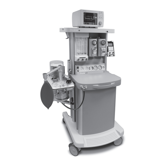
- Page 1 User Manual Prima 451 MRI Anaesthetic Machine A N A E S T H E S I A S O LU T I O N S 56536-en K Oct 2023...
- Page 3 The machine must be serviced to the schedule detailed in section 6.3. Details of these service operations are given in the Prima 451 Service Manual, available only for Penlon-trained engineers. For any enquiry regarding the servicing or repair of this...
- Page 4 Information contained in this manual is correct at the date of anaesthetist. publication. The policy of Penlon Limited is one of continued There can be considerable variation in the effect of improvement to its products. Because of this policy, Penlon...
- Page 5 5.8 Nuffield 200 Ventilator ................27 Prima 451 – User Manual...
- Page 6 6. AlphaLab GM3 gauss meter ................40 Prima 451 – User Manual...
- Page 7 Worn, broken, distorted, contaminated or missing components must be replaced immediately. Should such a repair become necessary it is recommended that a request for service advice be made to the nearest Penlon accredited agent. This device and any of its constituent parts must be repaired...
- Page 8 . b) When contacting Penlon for technical advice or when 2 . The Prima 451 MRI has been designed for use in an ordering spares, always state if the unit is used in a MRI environment only as a system (as listed above) .
- Page 9 . gases to a patient breathing system, as described 15 . Prima 451 anaesthetic machines must only be used with in Section 2 (Purpose) . Sigma Delta vaporizers installed on the Selectatec- Do not use the machine solely to provide large type backbar system .
- Page 10 13 . Use a gauss meter to measure the magnetic field when the system is positioned for use in the MR facility . Refer to section 5 .11 .2 when using a Prima 451 with an AV-S MRI Ventilator .
- Page 11 2 . Purpose The Prima 451 anaesthetic machine is for use by a professional operator in a professional healthcare environment, and must be continually attended when in use. The device is intended to provide controlled concentrations and flows of anaesthesia gases into a patient breathing...
- Page 12 (b) A pressure relief valve, factory set to 517 kPa (75 psi). This each cylinder yoke and pipeline inlet. prevents pressure build up under the diaphragm should any leakage develop across the reducing valve seat. Prima 451 – User Manual...
- Page 13 (normally open) Pressure gauge Reservoir Vaporizer Pressure regulator Pneumatic on/off switch Oxygen flush valve Flow control valve Pressure relief valve Non-return valve (variable) Power take-off point Audible alarm Filter (or test point) Restrictor Visual indicator Prima 451 – User Manual...
- Page 14 The AHD ensures a fresh gas mixture with a minimum of 30% (±3%) oxygen throughout the delivery range. See section 3.4 for a full description 3.3.6 Low Pressure Gas Tubing Diameter-indexed tubing is used for the low pressure gas system - see section 4. Prima 451 – User Manual...
- Page 15 The gauge for Air is positioned between oxygen and nitrous oxide. Unused gauge positions are blanked out. All pressure gauges are colour coded and labelled for the gases whose pressures they are indicating. The gauges are calibrated in kPa x 100. Prima 451 – User Manual...
- Page 16 The high-flow tube should not show any flow until more than 1 L/min is set. At flows above 1 L/min, the high-flow tube reading indicates the rate of flow for that gas. Prima 451 – User Manual...
- Page 17 (1) with interlock, mounted on the Selectatec compatible universal backbar, for the administration of volatile anaesthetic agents. WARNING 1. Prima 451 anaesthetic machines must only be used with Sigma Delta MRI vaporizers installed on the Selectatec-type backbar system. 2. Vaporizers must always be securely mounted, and never used free-standing.
- Page 18 (1), which also incorporates a circuit breaker. Switch labelling: I indicates On 0 indicates Off CAUTION In the event of malfunction of any device powered by the auxiliary sockets, check if the circuit breaker has tripped . Prima 451 – User Manual...
- Page 19 The ventilator (1) power supply unit is connected internally to the machine power supply. Note that the Prima 451 gas delivery switch (2) must be in the ‘On’ position for operation of the ventilator (see section 5.4), and refer also to section 3.4 in the AV-S MRI user manual.
- Page 20 (2) for detailed information on installation and operation. 3 .13 Nuffield 200 MRI Ventilator The Nuffield 200 MRI ventilator is mounted to the machine upright section, on either side of the Prima 451. For installation, refer to section 5.8. Prima 451 – User Manual...
- Page 21 Single flow tubes: Oxygen / Air / Nitrous Oxide 0 - 10 L/min Cascade flow tubes: Oxygen / Air / Nitrous Oxide 0 - 1000 ml/min 0 - 10 L/min (graduated 1 - 10 L/min) Prima 451 – User Manual...
- Page 22 Flow rates greater than 60 L/min could affect the fresh gas flow to the patient. 4 .6 Oxygen Failure Warning Devices 1. Gas system whistle (see section 3.3.2) 2. Visual indicator, direct pressure operated (see section 3.3.4) Prima 451 – User Manual...
- Page 23 10 A (nominal): maximum current depends on internal power usage Fuses T5AH ceramic (5 x 20 mm) high breaking capacity (on Live and Neutral on each outlet) The Prima 451 meets the requirements of EN 60601-1-2 (electromagnetic Electromagnetic Compatibility compatibility - requirements and tests) Prima 451 – User Manual...
- Page 24 (see section 1) and specific configurations. Specified MR environment The Prima 451 is approved for use in a magnetic resonance (MR) environment up to the 1000 gauss (100 mT) line, with scanners rated at 1.5 tesla and 3 tesla. CAUTION Special operational conditions apply to Prima 451 systems with the AV-S MRI ventilator - see Appendix 5.
- Page 25 NOTE These checks must be supplemented by periodic Function Testing, and full Service Testing by a Penlon-trained engineer to the Service Schedule given in the Prima 451 Service Manual . These checks will not in themselves ensure the safe use of the apparatus, which remains the responsibility of the qualified practitioner in charge of it .
- Page 26 3. Alternative systems (Bain, T-piece) – checked Refer to warnings 2 and 3 in section 1 Ventilator 1. Working and configured correctly 2. Refer to Penlon ventilator user manual for pre-use check instructions Airway equipment Full range required, working, with spares. Refer to warnings 2 and 3 in section 1 Suction...
- Page 27 Turn off the reserve cylinders during normal use. c) Nitrous oxide: cylinder pressure does not indicate cylinder content. 2. Ensure that all flowmeters are kept closed until gas supplies are required. Prima 451 – User Manual...
- Page 28 (2) is pressed, and that the flow ceases when the button is released. This test is most conveniently done after the breathing system has been attached, using the reservoir bag as an indicator of gas flow. Prima 451 – User Manual...
- Page 29 Vaporizers 5.3.4 Selectatec Compatible MRI Vaporizers with Interlock Penlon Sigma Delta MRI vaporizers can be supplied as part of WARNING the Prima 451 MRI system (see Appendix 2). Only MRI vaporizers with the Selectatec compatible interlock function will interlock if installed on a two station backbar manifold.
- Page 30 4. AV-S Ventilator (4). Check the power supply to the ventilator: a) Turn the Prima 451 gas delivery switch (5) to On. Press the ventilator on/off switch (6). Check that the green indicator light (7) is illuminated.
- Page 31 Connection to analysers and monitors Follow the instructions in the relevant user manual for connection to analysers and monitors. Interface cabling is shown for Prima 451 On/Off switch and A200SP Bag/Vent switch and spirometer. Ventilator connections shown are for AV-S MRI ventilator with spirometry and oxygen monitor.
- Page 32 11. Flow sensor - inspiratory (located within the absorber) 28. Oxygen sensor 12. Connectors (AV-S) - sensor - pressure monitor 13. Expiratory Valve - Absorber 14. Inspiratory Valve - Absorber 15. Inlet - from Ventilator bellows 16. Connector - Reservoir bag Prima 451 – User Manual...
- Page 33 For installation, refer to section 4.1 in the user manual supplied with the Nuffield 200 ventilator. The ventilator can be mounted on either side of the Prima 451. Always follow the pre-use check procedures given in the ventilator instruction manual .
- Page 34 That air, if fitted, continues to flow. NOTE All gases must be included in the pre-use check . 4. Reinstate the oxygen supply. Check that the flow of nitrous oxide is reinstated, and that the visual indicator turns green again. Prima 451 – User Manual...
- Page 35 1000 gauss line . 1. Plot the 1000 gauss line - see section 5.11.1. 2. Position the Prima 451 system (3), with the rear of the machine adjacent to the 1000 gauss line.
- Page 36 Servicing and Repair at the earliest opportunity, between patients. The Prima 451 must be only be serviced or repaired by a Appropriate disinfectants suitable for use with the Penlon-trained engineer, according to the schedule and anaesthetic machine are isopropyl alcohol, or alcohol wipes procedures given in the Prima 451 Service Manual.
- Page 37 1 . Set the brakes on the anaesthetic machine castors . 2 . Refer to the A200SP user manual and disconnect all cable connectors and hoses . 3 . Slacken the knob (3), and lift the absorber assembly from the pole-mount . Prima 451 – User Manual...
- Page 38 Maintenance Kit. Carry out an Inspection and Function Check Details of these service operations and ordering information for spares are given in the Prima 451 Series Service Manual, available only to engineers trained by the manufacturer. Delta Vaporizer 6 .3 .2 Refer to section 8 of the vaporizer user instruction manual.
- Page 39 WARNING Do not place any object on or in this machine unless it is specifically labelled to be used in an MRI scanning room and on the Prima 451 MRI anaesthesia system. Objects placed on or in this machine that are not designed for use with this anaesthesia system may be strongly attracted to the magnet and may cause serious injury or death when the machine is used in an MRI scanning room.
- Page 40 Auxiliary outlet (oxygen and air) Transportation: Remove accessories. Mass (weight) is indicated: Gas inlet pressure (pipeline or cylinder No magnetic objects supply) Do not push against the machine at a height greater than 1.1. metres Backbar leak check Prima 451 – User Manual...
- Page 41 This device is suitable for use in the specified electromagnetic environment. The user should assure that it is used in an electromagnetic environment as described below. Changes or modifications to this device, not expressly approved by Penlon Limited, could result in EMC issues with this device. Contact Penlon Limited for more information.
- Page 42 70% UT (30 % dip in UT) for 25/30 cycles 0% UT (100% dip in UT) for 250/300 cycles 0% UT (100 % dip in UT) for 250/300 cycles Power frequency (50 Hz) 30 A/m 30 A/m Magnetic field IEC 61000-4-8 Prima 451 – User Manual...
- Page 43 Appendix Appendix 5 Specified Magnetic Resonance (MR) environment The Prima 451 is approved for use in a magnetic resonance (MR) environment up to the 1000 gauss (100 millitesla) line, with scanners rated up to 1.5 tesla and 3 tesla. 1. Typical field strength distribution graph...
- Page 44 Appendix Appendix 6 AlphaLab GM3 gauss meter Using the gauss meter with a Penlon Prima 451 and AV-S MRI 1. Pre-use checks Check that the gauss meter sensor (1) is securely mounted at the rear of the top shelf of the Prima 451.
- Page 48 56536-en K Oct 2023 Part of the InterMed Group © Penlon Ltd. 2023 All rights reserved. Penlon, InterMed, A200SP and Sigma Delta are trademarks of Penlon Limited. All other trademarks are the property of their respective owners. Technical Support Penlon Limited...
Need help?
Do you have a question about the Prima 451 and is the answer not in the manual?
Questions and answers