Advertisement
Quick Links
Advertisement

Related Manuals for Ranco RDT-1110


Summary of Contents for Ranco RDT-1110
- Page 1 RDT-1110/2210/3210 Electronic controllers for refrigeration units...
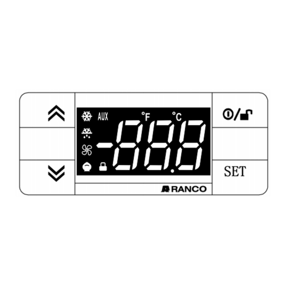
- Page 2 RDT-1110/2210/3210 USER INTERFACE RDT-1110/2210/3210 KEYS Standby (ESC)/To disable the keypad lock Press and release Press and release Scroll menu items Returns to the previous menu level Increases values Confirms parameter value Press for at least 5 sec Press for at least 5 sec...
- Page 3 LEDs Reduced SET / Economy LED Alarm LED Flashing: economy Setpoint active Permanently on: alarm active Quick flashing: access to level2 parameters Flashing: alarm acknowledged Off: otherwise Off: otherwise Compressor LED Defrost LED Permanently on: defrost active Permanently on: compressor active Flashing: a delay, a protection or a locked Flashing:...
- Page 4 RDT-1110 CONNECTIONS & APPLICATIONS Internal Buzzer Ambient T.E.V. Evaporator Compressor Valve Internal Buzzer Ambient Resistor Ambient = Ambient Valve = Valve Evaporator = Evaporator Compressor = Compressor Resistor = Resistor T.E.V. = Thermostatic Expansion Valve...
- Page 5 RDT-2210 CONNECTIONS & APPLICATIONS Internal Buzzer Ambient T.E.V. Compressor Valve Evaporator Internal Buzzer Ambient T.E.V. T.E.V. Compressor Compressor Valve Valve Evaporator Evaporator Ambient = Ambient Valve = Valve Evaporator = Evaporator Compressor = Compressor Internal Buzzer T.E.V. = Internal Buzzer = Thermostatic Expansion Valve...
- Page 6 RDT-3210 CONNECTIONS & APPLICATIONS Internal Buzzer Ambient T.E.V. Compressor Valve Evaporator Internal Buzzer Ambient Reversing Valve T.E.V. Evaporator Compressor Ambient = Ambient Valve = Valve Evaporator = Evaporator T.E.V. = Thermostatic Expansion Valve Compressor = Compressor = AUX Reversing valve = Reversing valve Internal Buzzer = Internal Buzzer...
- Page 7 LOCK SETPOINT MODIFICATION The keypad can be locked by entering the “Basic Commands” menu using and pressing within 2 seconds, or by programming the “LOC” parameter (see “diS” folder). If the keypad is locked, the “Basic Commands” menu can be accessed and the Setpoint displayed, but the value cannot be modified.
- Page 8 MOUNTING - DIMENSIONS The device is designed for panel mounting. Drill a 29x71 mm hole and insert the instrument; secure it with the special brackets provided. Do not install the instrument in damp and/or dirty places; in fact, it is suitable for use in places with ordinary or normal levels of pollution. Keep the area around the instrument cooling slots adequately ventilated.
- Page 9 ALARMS Label Fault Cause Effects Remedy • Display label E1 • measured values are outside operating • Alarm icon permanently on • check probe type (par. H00) Cold room range • Disable max/min alarm controller • check probe wiring probe1 faulty •...
- Page 10 PASSWORD Password “PA1”: used to access User parameters. The password is not enabled by default (PS1=0). To enable it (PS1≠0): press and hold for longer than 5 seconds, scroll through the parameters using until you see the label PS1, press to display the value, modify it using , then save it by pressing If enabled, it will be required in order to access the User parameters.
- Page 11 MACHINE STATUS MENU Access the Machine Status menu by pressing and releasing the key. If no alarms are active, the “SEt” label appears. Use the keys to scroll through all the folders in the menu: - AL: alarms folder (only visible if an alarm is active); - SEt: Setpoint setting folder;...
- Page 12 Temp. ≤ HAL - AFd temperature alarm LIABILITY AND RESIDUAL RISKS RANCO CONTROLS SRL declines any liability for damage due to: • installation/uses different from those specified and, in particular, not complying with the safety regulations and/or instructions given in this document;...
- Page 13 Every care has been taken in preparing this document; nevertheless RANCO CONTROLS SRL cannot accept liability for any damage resulting from its use. The same applies to any person or company involved in preparing and editing this document. RANCO CONTROLS SRL reserves the right to make aesthetic or functional changes at any time without notice.
- Page 14 NTC: -50.0 ... 70 °C Better than 0.5% of full scale +1 digit Resolution: 0.1 °C Buzzer: YES (depending on model) : 1 NTC (default) RDT-1110 Analogue inputs: : 2 NTC (default) RDT-2210/3210 : 1 voltage-free digital input; Digital inputs: RDT-1110/2210/3210...
- Page 15 - climate range A - measurement class 1 in the range -25 ... 15 °C (*) (* exclusively using RANCO probes) NOTE: The technical specifications given in this document regarding measurement (range, accuracy, resolution, etc.) refer to the instrument and not to any accessories provided, such as the probes.
- Page 16 DESCRIPTION OF RDT-1110 FAMILY RDT-1110 devices are controllers with 1 relay output, 1 temperature regulation sensor and 1 multifunctional Digital input. Temperature control and compressor start/stop, plus natural defrost on compressor stop. Heating function: the controller can also be used as a simple ON/OFF thermostat for heating applications.
- Page 17 TABLE OF 'USER' MENU PARAMETERS (RDT-1110) PAR. DESCRIPTION RANGE M.U. Temperature control SEtpoint LSE ... HSE °C/°F Compressor relay activation differential 0.1 ... 30.0 °C/°F HSE Maximum value that can be assigned to the Setpoint LSE ... 302 99.0 °C/°F Minimum value that can be assigned to the Setpoint -50.0 ...
- Page 18 TABLE OF 'INSTALLER' MENU PARAMETERS (RDT-1110) PAR. DESCRIPTION RANGE AP1 AP2 M.U. SEt Temperature control SEtpoint. LSE ... HSE °C/°F COMPRESSOR (“CP” folder) diF diFferential. Compressor relay activation differential. 0,1...30,0 °C/°F HSE Higher SEt. Maximum value that can be assigned to the Setpoint.
- Page 19 PAR. DESCRIPTION RANGE AP1 AP2 M.U. ALARMS (“AL” folder) Afd Alarm differential. 1.0 ... 50.0 °C/°F HAL Maximum temperature alarm. LAL...302 50.0 150 °C/°F LAL Minimum temperature alarm. -58.0...HAL -50.0 -50.0 °C/°F PAO Alarm exclusion time after re-activation following a power failure. 0 ...
- Page 20 PAR. DESCRIPTION RANGE AP1 AP2 M.U. CONFIGURATION (“CnF” folder) CONFIGURATION (“CnF” folder) If one or more parameters present in this forder are changed, the controller MUST be powered-off and than powered-on. Configuration of digital input . 0 = disabled; ±1 = defrost; ±2 = Deep Cooling; ±3 ±4 = Standby;...
- Page 21 DESCRIPTION OF RDT-2210 FAMILY RDT-2210 devices are controllers with 2 relay outputs, 2 temperature sensors (regulation and evaporator), a digital input. The relay output can be used to control: - compressor - defrost heating elements The second probe can be used to control the defrost cycle . The Digital inputs (D.I.1 ) can be used for: - Defrost activation - Delayed alarm...
- Page 22 TABLE OF 'USER' MENU PARAMETERS (RDT-2210) PAR. DESCRIPTION RANGE M.U. Temperature control SEtpoint LSE ... HSE °C/°F Compressor relay activation differential 0,1 ... 30,0 °C/°F HSE Maximum value that can be assigned to the Setpoint LSE ... 302 99,0 99,0 °C/°F Minimum value that can be assigned to the Setpoint -50.0 ...
- Page 23 TABLE OF 'INSTALLER' MENU PARAMETERS (RDT-2210) PAR. DESCRIPTION RANGE AP1 AP2 M.U. SEt Temperature control SEtpoint. LSE ... HSE °C/°F COMPRESSOR (“CP” folder) COMPRESSOR (“CP” folder) diF diFferential. Compressor relay activation differential. 0,1...30,0 °C/°F HSE Higher SEt. Maximum value that can be assigned to the Setpoint. LSE...302 99,0 99,0 °C/°F...
- Page 24 PAR. DESCRIPTION RANGE AP1 AP2 M.U. ALARMS (“AL” folder) Afd Alarm differential. 1.0 ... 50.0 °C/°F HAL Maximum temperature alarm. LAL...302 50.0 150 °C/°F LAL Minimum temperature alarm. -58.0...HAL -50.0 -50.0 °C/°F PAO Alarm exclusion time after re-activation following a power failure. 0 ...
- Page 25 PAR. DESCRIPTION RANGE AP1 AP2 M.U. CONFIGURATION (“CnF” folder) CONFIGURATION (“CnF” folder) If one or more parameters present in this forder are changed, the controller MUST be powered-off and than powered-on. Configuration of digital input . 0 = disabled; ±1 = defrost; ±2 = Deep Cooling; ±3 = door switch;...
- Page 26 DESCRIPTION OF RDT-3210 FAMILY RDT- 3210 devices are controllers with 3 relay outputs, 2 temperature sensors (regulation and evaporator), a digital input. Relay outputs 2 and 3 can be used to control: - compressor - defrost heating elements - evaporator fans The second probe can be used to control the defrost cycle and the evaporator fans.
- Page 27 TABLE OF USER MENU PARAMETERS (RDT-3210) PAR. DESCRIPTION RANGE M.U. Temperature control SEtpoint LSE ... HSE °C/°F Compressor relay activation differential 0,1 ... 30,0 °C/°F HSE Maximum value that can be assigned to the Setpoint LSE ... 302 99,0 99,0 °C/°F Minimum value that can be assigned to the Setpoint -58.0 ...
- Page 28 TABLE OF INSTALLER MENU PARAMETERS (RDT-3210) PAR. DESCRIPTION RANGE AP1 AP2 M.U. SEt Temperature control SEtpoint. LSE ... HSE °C/°F COMPRESSOR (“CP” folder) COMPRESSOR (“CP” folder) diF diFferential. Compressor relay activation differential. 0,1...30,0 °C/°F HSE Higher SEt. Maximum value that can be assigned to the Setpoint. LSE...302 99,0 99,0 °C/°F...
- Page 29 PAR. DESCRIPTION RANGE AP1 AP2 M.U. FANS (“FAn” folder) FANS (“FAn” folder) FSt Fans stop temperature. -58,0...302 50,0 50,0 °C/°F FAd Fan activation differential. 1,0 ... 50,0 °C/°F Fdt Fan activation delay after a defrost cycle. 0 ... 250 dFd Allows evaporator fan exclusion to be selected or not selected during defrosting. flag n (0) = no (it depends on FCO parameter);...
- Page 30 PAR. DESCRIPTION RANGE AP1 AP2 M.U. Display mode during defrost. 0 = display the temperature recorded by Pb1; 0/1/2 1 = lock recorded value of Pb1 at defrost start; 2 = display the “dEF” label. Ldd Timeout value for display unlock - dEF label. 0 ...
- Page 31 PAR. DESCRIPTION RANGE AP1 AP2 M.U. COPY CARD (“FPr” folder) COPY CARD (“FPr” folder) Programming parameter transfer from instrument to Copy Card. Programming parameter transfer from Copy Card to instrument . FUNCTIONS (“FnC” folder) FUNCTIONS (“FnC” folder) StP Self-testing procedure rES Reset HACCP alarms NOTE: If one or more parameters marked with (!) are modified, the controller MUST be switched off and then switched on again to ensure correct operation.
Need help?
Do you have a question about the RDT-1110 and is the answer not in the manual?
Questions and answers
Добрый день как вернать заводские настройки