Table of Contents

Subscribe to Our Youtube Channel
Related Manuals for Ranco EcoCool E7 Series


Summary of Contents for Ranco EcoCool E7 Series
- Page 1 Temperature and Defrost Controller Type E7 354-00027-001 Rev. D EcoCool ™ Controller and Configuration Software Installation and Configuration Type E7 EcoCool™ Electronic Temperature and Defrost Controllers ©2008 Invensys Controls All rights reserved.
-
Page 2: Table Of Contents
CONTENTS 1 How to use this manual..............4 2 Introduction . - Page 3 6.2.6 Saving and opening configuration files ..........23 6.2.7 Transferring configuration files .
-
Page 4: How To Use This Manual
1 HOW TO USE THIS MANUAL The following conventions are used in this manual. Callout Callout column: Column Callouts on the topics described are placed to the left of the text to allow the user to find the desired information quickly. Icons Icons Some parts of the text are highlighted using icons that have the following meanings:... -
Page 5: Installation
Optional Display To minimize temperature alarms during start up, defrost, and temperature fluctuations, alarm delay timers can be configured. The controllers can be configured to start defrosting based on the elapsed system-on time, the accumulated run time of the compressor, or the difference in temperature between the evaporator sensor and the control sensor. -
Page 6: Wiring The Controller
4.1.1 Wiring the controller WARNING: Before wiring the controller, make sure that the refrigeration unit, fan, heater, and controller are not connected to the electrical supply. Do not apply voltage to the digital input. WARNING: If the compressor and a fan are connected to the same relay on the controller, the total current drawn by the compressor and fan must not exceed the value shown in section 8.4 Terminations. -
Page 7: Mounting The Display
Mounting the display ED 1 The optional display can be flush mounted in a panel cutout up to 30ft (10m) from the controller. To mount the display flush to the panel, cut a 2.32” by 1” (64mm x 31mm) hole in the panel. Insert the display from the outside of the panel. Friction tabs on the sides of the display hold it in place. Display Mounting 2.32”... - Page 8 When the adjustment knob is set to the warm position and the controlled space temperature is equal to or greater than the Cut-In warm setpoint, the compressor or solenoid valve is energized until the controlled space temperature is equal to or less than the Cut-Out warm setpoint. Similarly, when the adjustment knob is set to cold, the compressor or solenoid valve is energized when the temperature is equal to or greater than the Cut-In cold setpoint and de-energized when the temperature is equal to or below the Cut-Out cold setpoint.
-
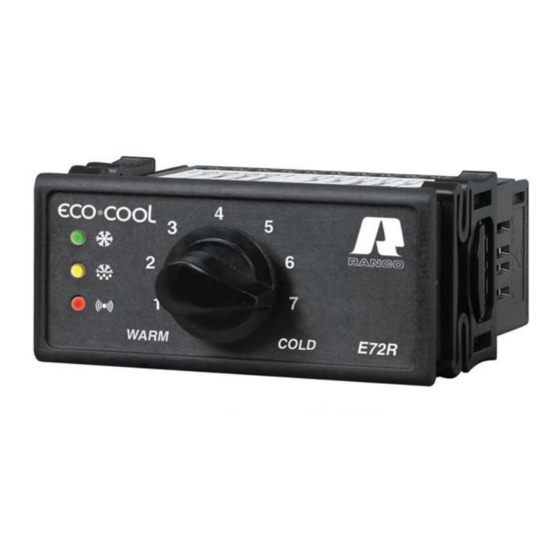
Page 9: Status Indications
Typical Compressor Cycles Compressor or Refrigeration Cut-In Cut-Out Compressor Compre essor Minimum Minimu On Time On Time Time Controller Compressor Compressor Compressor Power on Minimum Minimum Minimum Off Time On Time OFF Time at Startup 5.1.3 Status indications Three LEDs in the face of the controller indicate the status of the controller. The green LED illuminates while the compressor is powered on. The yellow LED illuminates while the controller is in a defrost cycle. - Page 10 Time Initiated Defrost Defrost Termination Defrost Termination Temp Compressor or Refrigeration Cut-In Cut-Out Time Controller Time to Time to Power on First Defrost Subsequent Defrosts Compressor Minimum On Time The controller can also be configured with a Temperature Initiated Defrost Function to start defrosting if it senses too great a difference between the control temperature and the evaporator temperature.
-
Page 11: Alarms
The E71R controller allows only off-cycle defrost by powering off the compressor. The E72R controller includes the following Defrost Method options: • Off Cycle: powers off the compressor • Electric: powers off the compressor and powers on a heating element •... -
Page 12: Faults
If the control temperature crosses an alarm threshold, the Temperature Alarm Time Delay begins counting down. If the timer expires and the temperature has not returned past the alarm differential, the red alarm LED on the controller (and optional display) illuminates. If the control temperature returns past the threshold by the amount of the differential before the alarm delay expires, the pending alarm is cancelled, and the timer is reset. -
Page 13: Display
5.1.6 Display The optional display has two digits, a negative sign, and three status LEDs. It displays the range -99 to 99 and the characters dF. Normally the display shows the control sensor temperature. The display shows the selected cut-out setpoint during adjustment and for three seconds after the adjustment is made. Sensor faults, temperature alarms, compressor or solenoid valve operation, and defrost are indicated by the display LEDs as they are by the controller LEDs. -
Page 14: Device And Software Configuration
6 DEVICE AND SOFTWARE CONFIGURATION Controller and interface box 6.1.1 Interface box overview The interface box allows communication between the controller and a computer for configuration download and upload and for firmware installation. Copy Card Jack Interface Box Cable Connection RS-232 DB-9 Power Jack Connector... -
Page 15: Ecocool Configuration Software
EcoCool configuration software 6.2.1 Minimum computer requirements To use the EcoCool configuration software your computer must meet or exceed the following minimum requirements: • Processor: Intel ® Pentium ® 4 500 MHz • Operating System: Microsoft® Windows® XP or Microsoft Vista® •... -
Page 16: Configuration
6.2.5.1 Configuration Use the configuration tab to specify the general operation of the controller and the controller’s use of parameters that are programmed on other tabs. Controller Operation temperature Units Select Fahrenheit or Celsius as the unit of temperature measurement and control. Changing this parameter changes the temperature unit throughout the controller program and recalculates temperature values shown in the tabs and on the display. -
Page 17: Setpoints
On/Off Function Select Enable to allow the adjustment knob to power off the compressor and controller and to adjust the setpoint. Select Disabled to allow only setpoint adjustment by the adjustment knob. Potentiometer (Adjustment Knob) These settings are unavailable if On/Off Function is disabled. Enter the Potentiometer Off Position to set the angle of the adjustment knob, relative to full counter clockwise, that powers off the controller and compressor. -
Page 18: Defrost
6.2.5.3 Defrost Use the Defrost tab to specify the conditions that cause defrosting to start and end. Defrost Function Define the defrost schedule timing interval or disable the defrost function. Selecting System Run Time specifies that the time interval between defrost (Time to subsequent defrosts) is defined by the time that the controller is powered on and restarts if the controller is power cycled. -
Page 19: Alarm
Defrost Duration Specifies the maximum duration of a defrost cycle (also called failsafe). When the Defrost Duration time expires the defrost cycle ends and, if Drip Time is configured, the Drip Time starts. If Drip Time is not configured, the controller immediately powers on the compressor and resumes refrigeration. Drip Time Specifies how long the controller waits to resume refrigeration after defrost. -
Page 20: Compressor
Low Temperature Alarm – Warm Position Specifies the sensed low temperature setpoint that causes an alarm when the adjustment knob is in the warm position. Control sensor temperatures equal to or less than this threshold cause an alarm when the adjustment knob is in the warm position. High Temperature Alarm –... -
Page 21: Fault
Compressor Minimum Off Time at Start Up Specifies how long the compressor remains powered off when the controller is powered on. Compressor Minimum On Time Specifies the minimum time that the compressor is powered on regardless of whether the control temperature decreases to less than the Cut-Out setpoint. Specify how long the compressor remains powered on before normal controller programming powers it off. -
Page 22: Display
6.2.5.7 Display Use the Display tab to specify what is displayed during defrost and to specify a display temperature offset. Defrost Display Lock Select Show current “TEMP” to display the sensed control temperature during defrost. Select LOCK Display at Temp. Reading prior to Defrost to display, for the entire defrost cycle, drip time, and until the first compressor cut-out after defrost, the temperature that was sensed at the moment the defrost cycle started. -
Page 23: Fan
6.2.5.8 Use the Fan tab to configure fan operation when Defrost Function is disabled. Defrost Function may be disabled in medium and warm temperature applications where defrost occurs naturally during the compressor off cycle (see 6.2.5.3 Defrost). With Defrost Function disabled, Evaporator Fan Operation during Compressor off-cycle allows the fan to be powered on or powered off during the entire compressor off cycle. -
Page 24: Transferring Configuration Files
6.2.7 Transferring configuration files You can use the interface box and your computer to transfer configuration files between EcoCool configuration software and a controller. Configuration files can be downloaded to the controller or copy card and uploaded to your computer. Disconnect power to the controller. -
Page 25: Transferring Firmware Between Ecocool Configuration Software And A Controller
6.2.8 Transferring firmware between EcoCool configuration software and a controller You can use the interface box and your computer to transfer firmware between EcoCool configuration software and a controller or copy card. Controller firmware can be updated in a controller using a copy card or EcoCool configuration software. Firmware can be reinstalled in a controller, if it becomes corrupted, using EcoCool configuration software. -
Page 26: Restoring Default Values
6.2.10 Restoring default values Click Default Value to load default values into all parameters on all tabs in the EcoCool configuration software. Popup windows indicate which parameters are being changed. You can download the default values to a controller by following the steps in section 6.2.6. Copy card You can use a copy card to transfer firmware and configuration files into a controller or EcoCool configuration software. -
Page 27: Downloading A Configuration From Ecocool Configuration Software Into A Copy Card
6.3.2 Downloading a configuration from EcoCool configuration software into a copy card Open a configuration file in the EcoCool configuration software. Connect the copy card to the Interface Box. Click Download Config to Controller. Click OK and follow the on screen prompts. During the file transfer, both LEDs on the copy card are illuminated. - Page 28 Parameter list The Parameter List Table includes the default value, range, and resolution of all parameters that can be set using the EcoSoft Program. Case name, location or ID: ____________________________________________________________________ Configuration name (e.g. Ice Cream.prm): __________________________________________________________ Configuration Parameter Description Default Resolution Value Controller Operation...
- Page 29 Configuration Parameter Description Default Resolution Value Temperature Alarm Enable or Disable Enable Disable High Temperature Alarm – -5ºC -40°C 40°C Warm Position (ºC or ºF) (23°F) (-40°F) (104°F) Low Temperature Alarm – -25ºC -40°C 40°C Warm Position (ºC or ºF) (-13°F) (-40°F) (104°F)
-
Page 30: Troubleshooting
7 TROUBLESHOOTING Problem Solution The red alarm LED remains illuminated after controller startup; a check sum error Re-install the firmware using EcoSoft Program (6.2.8) or a copy card (6.3.4). has occurred. A temperature alarm occurs soon after startup. Increase the Temperature Alarm Disable Time after Start up (see 6.2.5.4). A temperature alarm occurs soon after defrost. -
Page 31: Technical Specifications
8 TECHNICAL SPECIFICATIONS Electrical rating • Supply voltage nominal range: 90V AC to 240V AC (switching power supply) • Frequency: 50Hz or 60Hz + 1% sinusoidal • Power consumption: Maximum 3W Actual measured: 2.3W Temperature control range -40°F 0 to 104°F (-40°C to 40°C) Accuracy ±... -
Page 32: Responsibility And Residual Risks
To the maximum extent permitted by law, in no event shall the liability of Ranco exceed the amount paid to Ranco for the quantities of its products giving rise to the liability.
Need help?
Do you have a question about the EcoCool E7 Series and is the answer not in the manual?
Questions and answers