Advertisement
Quick Links
ENERVEX
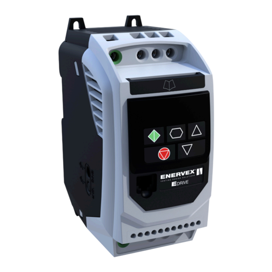
EDRIVE MOTOR CONTROLLER
3916101 06.16
UL File E483993
ENERVEX Inc.
1685 Bluegrass Lakes
Parkway
Alpharetta, GA 30004
USA
READ AND SAVE THESE INSTRUCTIONS!
P: 770.587.3238
F: 770.587.4731
T: 800.255.2923
info@enervex.com
www.enervex.com
Installation & Operating Manual
Advertisement

Subscribe to Our Youtube Channel
Related Manuals for ENERVEX EDRIVE


Summary of Contents for ENERVEX EDRIVE
- Page 1 ENERVEX EDRIVE MOTOR CONTROLLER 3916101 06.16 Installation & Operating Manual READ AND SAVE THESE INSTRUCTIONS! UL File E483993 ENERVEX Inc. P: 770.587.3238 1685 Bluegrass Lakes F: 770.587.4731 Parkway T: 800.255.2923 Alpharetta, GA 30004 info@enervex.com www.enervex.com...
- Page 2 MCB. Do not attempt to carry out any repair of the EDrive. In the Suitably rated fuses or MCB should be fitted in the mains case of suspected fault or malfunction, contact your local supply to the drive, according to any local legislation or ENERVEX Representativefor further assistance.
- Page 3 3916101 06.16 Content 1. GENERAL INFORMATION 1.1 Introduction ............4 1.3 Components ............4 1.4 Shipping ............5 1.5 Accessories ............5 1.6 Listings .............5 1.7 Warranty ............5 2. SPECIFICATIONS AND DIMENSIONS 2.1 Specifications ...........6 2.2 Capacities ............7 3. MECHANICAL INSTALLATION 3.1 Positioning ............8 3.2 Floor and Roof Mounting ........9 3.3 Ceiling Mounting ..........9 3.4 Connection to Duct ...........10...
- Page 4 3916101 06.16 QUICK START GUIDE Step Action See Section Page Identify the Enclosure Type, Model Type and ratings of your Identifying the Drive by Model Number drive from the model code on the label. In particular - Check the voltage rating suits the incoming supply - Check the output current capacity meets or exceeds the full load current for the intended motor Unpack and check the drive.
- Page 5 3916101 06.16 1. PRODUCT INFORMATION 1.1 INTRODUCTION The EDrive units are shipped in a carton box. These instructions provide both general guidelines and special requirements for all parts in the EDrive product If other components are shipped, they will appear on the line.
- Page 6 3916101 06.16 2. SPECIFICATIONS AND DIMENSIONS 2.1 Environmental Operational ambient temperature range Open Drives 14 ...122°F / -10 … 50°C (frost and condensation free) Enclosed Drives 14 ...104°F / -10 ... 40°C (frost and condensation free) Storage ambient temperature range -40 ...
- Page 7 3916101 06.16 2.3 General Input Power Supply Requirements EDrive is designed to meet the UL requirements. For an up to Supply 200 – 240 RMS Volts for 230 Volt rated units, + /- 10% date list of UL compliant products, please refer to UL listing Voltage variation allowed.
- Page 8 3916101 06.16 3. MECHANICAL INSTALLATION 3.1 General The EDrive should be mounted in a vertical position only, on a flat, flame resistant, vibration free mounting using the integral mounting holes or DIN Rail clip (Frame Sizes 1 and 2 only).
- Page 9 4.2 Grounding Guidelines DANGER The ground terminal of each EDrive should be individually This EDrive contains high voltage capacitors connected DIRECTLY to the site ground bus bar (through the that take time to discharge after removal of filter if installed).
- Page 10 A fixed installation is required according to IEC61800-5-1 with a suitable disconnecting device installed between the EDrive and the AC Power Source. The disconnecting device must conform to the local safety code / regulations (e.g. within Europe, EN60204-1, Safety of machinery).
- Page 11 The motor should be connected to the EDrive U, V, and W terminals using a suitable 3 or 4 conductor cable. Where a 3 core cable is utilised, with the shield operating as an earth...
- Page 12 3916101 06.16 4.7 Motor Thermal Overload Protection Motor Incoming The drive has an in-built motor thermal overload function; this Nameplate Connection Supply Voltage is in the form of an “I.t-trP” trip after delivering >100% Voltages of the value set in P-08 for a sustained period of time (e.g. 150% for 60 seconds).
- Page 13 3916101 06.16 4.9 Connection Diagram Power Connections Control Connections Incoming Power Supply + 24V (100mA) User Output Isolator / Disconnect Digital Input 1 Drive Run / Stop MCB or Fuse Digital Input 2 Forward / Reverse Input Choke (optional) Digital Input 3 Analog / Preset Speed Input Filter (optional) + 10 Volt Output...
- Page 14 Fig 14 3916101 06.16 4.10 Control Terminal Connections Default Connections Control Terminal Signal Description +24Vdc user output, 100mA +24Vdc User Output DO NOT CONNECT AN EXTERNAL VOLTAGE SOURCE TO THIS TERMINALS Digital Input 1 Positive Logic: “Logic 1” input voltage range: 8V ... 30V DC Digital Input 2 “Logic 0”...
- Page 15 3916101 06.16 5. OPERATION 5.1 Managing The Keypad The drive is configured and its operation monitored via the keypad and display. Used to display real-time information, to access and exit parameter NAVIGATE edit mode and to store parameter changes Used to increase speed in real-time mode or to increase parameter values in parameter edit mode Used to decrease speed in real-time mode or to decrease parameter DOWN...
- Page 16 Hz, and the slip compensation (where motor speed is maintained at a constant value regardless of applied load) for the motor is disabled. Entering the value from the motor nameplate enables the slip compensation function, and the EDrive display will now show motor speed in RPM.
- Page 17 A 0-20 = 0 to 20mA Signal t 4-20 = 4 to 20mA Signal, the EDrive will trip and show the fault code 4-20F if the signal level falls below 3mA r 4-20 = 4 to 20mA Signal, the EDrive will run at Preset Speed 1 (P-20) if the signal level falls below 3mA...
- Page 18 Parameter P-27 defines the centre point of the skip frequency band, and is used in conjunction with P-26. The EDrive output frequency will ramp through the defined band at the rates set in P-03 and P-04 respectively, and will not hold any output frequency within the defined band.
- Page 19 3916101 06.16 Par. Description Minimum Maximum Default Units P-29 V/F Characteristic Adjustment Frequency P-09 This parameter in conjunction with P-28 sets a frequency point at which the voltage set in P-29 is applied to the motor. Care must be taken to avoid overheating and damaging the motor when using this feature P-30 Start Mode, Automatic Restart, Fire Mode Operation...
- Page 20 Index 2 : Display Scaling Source Allows the user to program the EDrive to display an alternative output unit scaled from either output frequency (Hz), Motor Speed (RPM) or the signal level of PI feedback when operating in PI Mode.
- Page 21 A 0-20 = 0 to 20mA Signal t 4-20 = 4 to 20mA Signal, the EDrive will trip and show the fault code 4-20F if the signal level falls below 3mA r 4-20 = 4 to 20mA Signal, the EDrive will run at Preset Speed 1 (P-20) if the signal level falls below 3mA...
- Page 22 3916101 06.16 Par. Description Minimum Maximum Default Units P-53 Vector Mode Gain 200. 50.0 Single Parameter for Vector speed loop tuning. Affects P & I terms simultaneously. Not active when P-51 = 1 P-54 Maximum Current Limit 175.0 150.0 Defines the max current limit in vector control modes . P-55 Motor Stator Resistance 0.00...
- Page 23 3916101 06.16 6.4 P-00 Read Only Status Parameters Par. Description Explanation P00-01 1st Analog input value (%) 100% = max input voltage P00-02 2nd Analog input value (%) 100% = max input voltage P00-03 Speed reference input (Hz / RPM) Displayed in Hz if P-10 = 0, otherwise RPM P00-04 Digital input status...
- Page 24 3916101 06.16 Par. Description Explanation Drive power up time (life time) (Hours) Total lifetime of drive with power applied P00-43 P00-44 Phase U current offset & ref 100% = max input voltage Phase V current offset & ref Displayed in Hz if P-10 = 0, otherwise RPM P00-45 P00-46 Phase W current offset &...
- Page 25 3916101 06.16 7. MODBUS RTU COMMUNICATIONS 7.1 Introduction Protocol Modbus RTU The EDrive can be connected to a Modbus RTU network Error Check CRC via the RJ45 connector on the front of the drive. See specifications to the right. Baud Rate...
- Page 26 Modbus command. The Register number for each parameter P-04 to P-60 is defined as 128 + Parameter number, e.g. for parameter P-15, the register number is 128 + 15 = 143. Internal scaling is used on some parameters, for further details, please contact your ENERVEX Representative.
- Page 27 3916101 06.16 8. TROUBLESHOOTING 8.1 Fault Code Messages Fault Description Suggested Remedy Code No Fault None required no-Flt Brake channel over current Check external brake resistor condition and connection wiring 01-b Brake resistor overload The drive has tripped to prevent damage to the brake resistor OL-br Output Over Current Instantaneous Over current on the drive output.
- Page 28 ENERVEX Inc. P: 770.587.3238 1685 Bluegrass Lakes F: 770.587.4731 Parkway T: 800.255.2923 Alpharetta, GA 30004 info@enervex.com www.enervex.com...
Need help?
Do you have a question about the EDRIVE and is the answer not in the manual?
Questions and answers