Table of Contents
Advertisement
Quick Links
ENERVEX
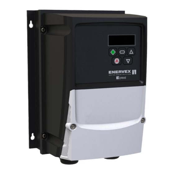
EDRIVE E3 MOTOR CONTROLLER
010.3210.0619 06.21
NEMA 4X (IP 66)
0.37kW - 22kW / 0.5HP - 30HP
110 - 480V Single and Three-Phase Input
UL File E226333
ENERVEX Inc.
1685 Bluegrass Lakes
Parkway
Alpharetta, GA 30004
USA
READ AND SAVE THESE INSTRUCTIONS!
P: 770.587.3238
F: 770.587.4731
T: 800.255.2923
info@enervex.com
www.enervex.com
Installation & Operating Manual
Advertisement
Table of Contents

Subscribe to Our Youtube Channel
Related Manuals for ENERVEX EDRIVE E3


Summary of Contents for ENERVEX EDRIVE E3
- Page 1 ENERVEX EDRIVE E3 MOTOR CONTROLLER 010.3210.0619 06.21 Installation & Operating Manual NEMA 4X (IP 66) 0.37kW - 22kW / 0.5HP - 30HP 110 - 480V Single and Three-Phase Input READ AND SAVE THESE INSTRUCTIONS! UL File E226333 ENERVEX Inc. P: 770.587.3238 1685 Bluegrass Lakes F: 770.587.4731...
-
Page 2: Table Of Contents
010.3210.0619 06.21 1. GENERAL INFORMATION AND RATINGS 6.2 Parameter List ..........20 1.1 Identifying the Drive by Model Number .....5 6.3 Parameter Functions .........22 1.2 Product Rating Label Location ......5 6.4 P-00 Read Only Status Parameters ....37 1.3 Understanding the Rating Label .......5 7. - Page 3 010.3210.0619 06.21 DECLARATION OF CONFORMITY This user guide is the “original instructions” document. ENERVEX Inc. hereby states that the EDrive E3 product range All non-English versions are translations of the “original conforms to the relevant safety provisions of the following instructions”.
- Page 4 Do not attempt to carry out any repair of the EDrive E3. In the case will be limited by the fuses or MCB. Suitably rated fuses or MCB of suspected fault or malfunction, contact your local ENERVEX should be fitted in the mains supply to the drive, according to any Representative for further assistance.
-
Page 5: General Information And Ratings
1200 = 1 x 120V 1.2. PRODUCT RATING LABEL LOCATION 2200 = 3 x 230V All EDrive E3 models carry a rating label, which can be located 4200 = 3 x 460V according to Fig 2: 5700 = 3 x 575V 1.3. -
Page 6: Specifications And Dimensions
010.3210.0619 06.21 2. SPECIFICATIONS AND DIMENSIONS 2.1 ENVIRONMENTAL Operational ambient temperature range Open Drives 14 ...122°F / -10 … 50°C (frost and condensation free) Enclosed Drives -4 ...104°F / -20 ... 40°C (frost and condensation free) Storage ambient temperature range -40 ... -
Page 7: Single Phase Operation Of Three Phase Drives
For input supplies which have supply imbalance greater COMPLIANCE than 3% (typically the Indian sub- continent & parts of Asia All EDrive E3 units are designed to meet the UL Pacific including China) ENERVEX Drives recommends the requirements. For an up to date list of UL compliant installation of input line reactors. -
Page 8: Emc Filter Disconnect
010.3210.0619 06.21 2.7 EMC FILER DISCONNECT Drives with an EMC filter have an inherently higher leakage current to Ground (Earth). For applications where tripping occurs the EMC filter can be disconnected (on IP20 units only) by completely removing the EMC screw on the side of the product. -
Page 9: Mechanical Installation
010.3210.0619 06.21 3. MECHANICAL INSTALLATION 3.1 GENERAL The EDrive E3 should be mounted in a vertical position only, on a flat, flame resistant, vibration free mounting using the integral mounting holes or DIN Rail clip (Frame Sizes 1 and 2 only). -
Page 10: Removing Terminal Cover
010.3210.0619 06.21 3.4 REMOVING THE TERMINAL COVER To access the connection terminals, the drive front cover needs to be removed. Removing the 2 screws on the front of the product allows access to the connection terminals, as shown to the right 3.5 ROUTINE MAINTENANCE The drive should be included within the scheduled maintenance program so that the installation maintains a... -
Page 11: Electrical Installation
4.2 GROUNDING GUIDELINES DANGER The ground terminal of each EDrive E3 should be individually This EDrive E3 contains high voltage capacitors connected DIRECTLY to the source breaker panel ground bus that take time to discharge after removal of bar (through the filter if installed). -
Page 12: Incoming Power Connection
A fixed installation is required according to IEC61800-5-1 with a suitable disconnecting device installed between the EDrive E3 and the AC Power Source. The disconnecting device must conform to the local safety code / regulations (e.g. within Europe, EN60204-1, Safety of machinery). -
Page 13: Motor Terminal Box Connections
The motor should be connected to the EDrive E3 U, V, and W terminals using a suitable 3 or 4 core cable. Where a 3 core cable is utilised, with the shield operating as an earth... -
Page 14: Connection Diagram
010.3210.0619 06.21 4.7 CONNECTION DIAGRAM Sec. Page Grounding (PE) Connection Incoming Power Connection Fuse / Circuit Breaker Selection 4.3.2 Optional Input Choke 4.3.3 Optional External EMC Filter 4.10 Not Used Optional Brake Resistor 4.11 Motor Connection Analog Output 4.8.1 Relay Output 4.8.2 Not Used Analog Inputs... -
Page 15: Control Terminal Connections
010.3210.0619 06.21 4.8 CONTROL TERMINAL CONNECTIONS Default Connections Control Terminal Signal Description +24Vdc user output, 100mA +24Vdc User Output DO NOT CONNECT AN EXTERNAL VOLTAGE SOURCE TO THIS TERMINALS Digital Input 1 Positive Logic: “Logic 1” input voltage range: 8V ... 30V DC “Logic 0”... -
Page 16: Motor Thermal Overload Protection
7 Permissible cable length with additional external EMC filter. 4.11 OPTIONAL BRAKE RESISTOR EDrive E3 Frame Size 2 and above units have a built in Brake Transistor. This allows an external resistor to be connected to the drive to provide improved braking torque in applications that require this. - Page 17 Stored charge may be present after disconnecting the mains power. Allow a minimum of 10 minutes discharge after power off before attempting any connection to these terminals. Suitable resistors and guidance on selection can be obtained from your ENERVEX Sales Partner.
-
Page 18: Operation
010.3210.0619 06.21 5. OPERATION 5.1 MANAGING THE KEYPAD The drive is configured and its operation monitored via the keypad and display. Used to display real-time information, to access and exit parameter NAVIGATE edit mode and to store parameter changes Used to increase speed in real-time mode or to increase parameter values in parameter edit mode Used to decrease speed in real-time mode or to decrease parameter DOWN... -
Page 19: Changing Parameters
5.7 LED DISPLAY The EDrive E3 has a built in 6-digit 7-Segment LED display. In order to display certain warning, the following methods are used. 5.7.1 LED Display Layout Fig 7 See Fig 5 5.7.2 LED Display Meaning... -
Page 20: Parameters
010.3210.0619 06.21 6. PARAMETERS 6.1 STANDARD PARAMETERS The parameter set is arranged in Groups according to the following structure: Access to all parameter groups is controlled by setting P-14 as follows: P-14 = P-37 (Factory setting: 101) Allows Extended Parameter Access P-14 = P-37 + 100 (Factory Setting: 201) Allows Advanced Parameter Access In order to prevent possible damage to the drive and connected machinery, certain parameters are locked during operation of the drive to prevent change. - Page 21 010.3210.0619 06.21 6.2.2 Extended Parameters...
-
Page 22: Parameter Functions
Working in RPM ( Relevant Parameters) EDrive E3 normally uses frequency for all speed related parameters, e.g. Minimum and Maximum Output Frequency. It is also possible to work directly in RPM, by setting the above parameter to the relevant rated speed from the connected motor... - Page 23 010.3210.0619 06.21 When set to the default value of zero, all speed related parameters are displayed in Hz, and slip compensation for the motor is disabled. Entering the value from the motor nameplate enables the slip compensation function, and the EDrive display will also now show motor speed in RPM.
- Page 24 010.3210.0619 06.21 Speed Limits ( Relevant Parameters) These parameters define the range of output frequency and therefore the speed range through which the drive will operate. As described above: • If P-10 = 0, Values are Hz • If P-10 <> 0, Values are RPM Dependent on the speed reference selection, the operation will be as follows: For Analog Speed Reference: Applying 0% analog signal results in the speed reference of P-02.
- Page 25 010.3210.0619 06.21 Motor Energy Optimisation: Reduces energy losses in the motor under part load conditions by reducing motor flux. This function should not be used in applications which have large sudden load step changes, or for PI control applications, as it may cause instability in the control or over current trip.
- Page 26 010.3210.0619 06.21 6.3.3 Input and Output Functions Analog Inputs - Format ( Relevant Parameters) Analog Inputs - AI1 Scaling & Offset ( Relevant Parameters)
- Page 27 010.3210.0619 06.21 Relay Output Functions ( Relevant Parameters) Analog Output Functions ( Relevant Parameters)
- Page 28 010.3210.0619 06.21 6.3.4 Common Functions Parameter Access Control & Locking ( Relevant Parameters) Local/Remote ( Relevant Parameters) Preset Speeds ( Relevant Parameters) Start Mode, Auto Restart and Fire Mode ( Relevant Parameters)
- Page 29 010.3210.0619 06.21...
- Page 30 010.3210.0619 06.21 The Fire Mode function is designed to ensure continuous operation of the drive in emergency conditions until the drive is no longer capable of sustaining operation. The Fire Mode input may be a normally open (Close to Activate Fire Mode) or Normally Closed (Open to Activate Fire Mode) according to the setting of P-30 Index 2.
- Page 31 010.3210.0619 06.21 DC Injection Braking ( Relevant Parameters) Spin Start ( Relevant Parameters) Dynamic braking ( Relevant Parameters) Display Scaling ( Relevant Parameters)
- Page 32 010.3210.0619 06.21 PI Control ( Relevant Parameters) Standby Mode & Wake Up ( Relevant Parameters)
- Page 33 Current Limit ( Relevant Parameters) 6.3.4 Advanced Functions Autotune ( Relevant Parameters) Motor Control Methods EDrive E3 may be used with the following motor types: • A synchronous Induction Motors (IM) • S ynchronous Permanent Magnet AC Motors (PM) • Brushless DC Motors (BLDC) •...
- Page 34 Asynchronous Induction Motors (IM) Vector Control EDrive E3 factory default parameters are intended for use with IM motors where the power rating of the motor is approximately the same or slightly less than the indicated power rating of the drive. In this case, it should be possible to operate the motor without any parameter adjustment at all for initial testing.
- Page 35 Synchronous Permanent Magnet AC Motors (PM), BLDC Motors and LSPM Motors Suitable Motors EDrive E3 provides open loop control of permanent magnet AC motors including BLDC and LSPM type, intended to allow the use of high efficiency motors in simple applications. Both interior and exterior magnets type motors are supported.
- Page 36 010.3210.0619 06.21 • Select the appropriate motor type in P-51 For PM motor control P-51 = 2 For BLDC motor control P-51 = 3 For LSPM motor control P-51 = 5 • Carry out an Autotune. An Autotune MUST be carried out. This is achieved by setting P-52 = 1.
-
Page 37: Read Only Status Parameters
010.3210.0619 06.21 6.4 P-00 READ ONLY STATUS PARAMETERS... - Page 38 010.3210.0619 06.21...
-
Page 39: Modbus Rtu Communications
Register number for each parameter P-04 to P-60 is defined as 128 + Parameter number, e.g. for parameter P-15, the register number is 128 + 15 = 143. Internal scaling is used on some parameters, for further details, please contact your ENERVEX Representative. -
Page 40: Troubleshooting
010.3210.0619 06.21 8. TROUBLESHOOTING 8.1 FAULT CODE MESSAGES Fault Description Suggested Remedy Code no-Flt No Fault None required 01-b Brake channel over current Check external brake resistor condition and connection wiring Brake resistor overload The drive has tripped to prevent damage to the brake resistor OL-br Output Over Current Instantaneous Over current on the drive output. - Page 41 010.3210.0619 06.21 NOTES...
- Page 42 010.3210.0619 06.21 NOTES...
- Page 43 010.3210.0619 06.21 NOTES...
- Page 44 ENERVEX Inc. P: 770.587.3238 1685 Bluegrass Lakes F: 770.587.4731 Parkway T: 800.255.2923 Alpharetta, GA 30004 info@enervex.com www.enervex.com...
Need help?
Do you have a question about the EDRIVE E3 and is the answer not in the manual?
Questions and answers