Advertisement
Quick Links
Advertisement

Summary of Contents for Heat Outdoors 906454
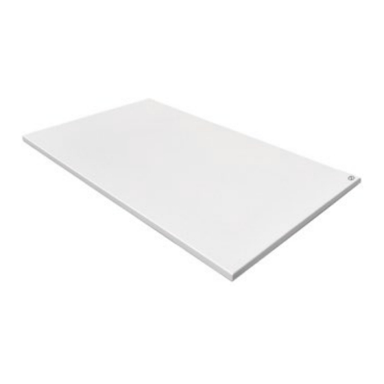
- Page 1 Shadow Carbon Heating Panel Safety Instructions and Operation Manual 906454 906455 906456 906457 906458 Heat Outdoors www.heat-outdoors.co.uk Unit 9, Stort Valley Industrial Estate 01279 466500 Stansted Road, Bishop’s Stortford info@heat-outdoors.co.uk Hertfordshire, United Kingdom CM23 2TU...
- Page 2 Contents Important Information ......................3 Product Information ....................... 6 Assembly Instructions ......................9 Maintenance ........................19...
- Page 3 1┃WARNING & PRECAUTION Read this manual carefully before starting or using the device. Always store the manual in the immediate vicinity of the device or its site of use! Read all safety warnings and all instructions. Failure to follow the warnings and instructions may result in electric shock, fire and / or serious injury.
- Page 4 been given supervision or instruction concerning use of the appliance in a safe way and understand the hazards involved. Children shall not play with the appliance. Cleaning and user maintenance shall not be made by children Without supervision. Warning Children of less than 3 years should be kept away unless continuously supervised.
- Page 5 Remove all the protective films(both on the front and on the back) before using. Be sure the input voltage is between 220-240V, 50Hz, and power supply has been strictly in accordance with IEC, left is null wire and right is live wire, and also well grounded.
- Page 6 Switch the device off and disconnect the power cable from the mains socket when the device is not in use. Do not under any circumstances use the device if you detect damages on the mains plug or power cable. If the supply cord is damaged, it must be replaced by the manufacturer, its service agent or similarly qualified persons in order to avoid a hazard.
-
Page 7: Technical Information
3┃TECHNICAL INFORMATION Heating element Carbon Heating way Far infrared heating Input Voltage 220-240V/50Hz Surface temperature F series for wall : Mainly 85-95℃ F series for ceiling : Mainly 90-105℃ Frame Frameless IP grade IP54 (exclude plug) Over heating protection Power cord length 1.9m... - Page 8 4┃SCOPE OF SUPPLY Only for wall products Only for ceiling products (A) Heating Device x 1 (B) Drilling template x 1 (C) Manual x 1 Wall mounting accessories: (D) Gray Dowels x 4 Self-tapping Screws Ceiling mounting accessories: Metal Expansion Tubes (G) Screws (H) Spring Toggles Washers...
-
Page 9: Installation
Tips: 1. D and E are only for walling mounting, F,G,H and I are only for ceiling mounting. 2. F and G are applied to concrete ceilings, whereas G,H and I are used on gypsum board ceilings. 5┃DEVICE STRUCTURE Designation 1 Frameless shell ①... - Page 10 2. Mark the positions for the bore holes onto the drilling template (B) if there are no existing marks. Stick the drilling template on the wall. Drill four 8mm holes, and Insert the gray dowels(D) into the holes by a hammer. Insert the Self-tapping Screws(E) into the dowels and fasten the...
- Page 11 5. Slid the device to make the screws into the correct positions as showing in below drawing. 6. Plug in to start using the heating device . Do pull out the plug when not in use. Instruction for Ceiling Mounting Before starting the installation, please make sure to determine the material of the ceiling.
- Page 12 Step3: Insert the metal expansion tubes(F) into the drilled holes. Hanging unit Step4: Thread screws(G) through the Hanging units holes, then tighten them into the tubes. b. Gypsum Board Ceiling Installation: Step1:Determine the drilling position. 1. Please note that the spring toggles (H) are designed for gypsum boards or wooden ceilings with a thickness ranging from 9-18mm.
- Page 13 18mm Φ H anging unit Step4: Tighten the screws. Instruction for Ceiling Mounting: Only if below ceiling mounting sets included. X 2 SETS 1. Measure and mark the correct distances "a" and "b" on the concrete ceiling where you want to install. Hole Distances of Panel Size/mm Screws/mm...
- Page 14 Similar to 705*605 a360*b240mm Similar to 1005*605 a480*b240mm Similar to 1205*755 a660*b390mm Similar to 1205*905 a660*b470mm 2. Fix the hanging units to the ceiling. (Concrete ceilings use metal expansion tubes, and gypsum board ceilings us e spring toggles) 3. Take off all the four plastic caps from rear of the panel. 4.
-
Page 15: Troubleshooting
(View after mounting finished) 7┃TROUBLESHOOTING Problem Reason Measure It has noise when Due to the structure stress It is a normal original charged with of the heat insulator. phenomenon. electricity Don't worry about it. The surface of the Due to the thermal It is a normal device was slightly expansion of the surface... - Page 16 8┃MAINTENANCE & SERVICING Activities required before starting maintenance Warning of electrical voltage Do not touch the mains plug with wet or damp hands. • Hold onto the mains plug while pulling the power cable out of the mains socket. • Allow the device to cool down completely. Warning of electrical voltage Tasks which require the housing to be opened must only be carried out by authorized specialist companies.


Need help?
Do you have a question about the 906454 and is the answer not in the manual?
Questions and answers