Advertisement
Quick Links
Technical Support and E-Warranty Certificate www.vevor.com/support
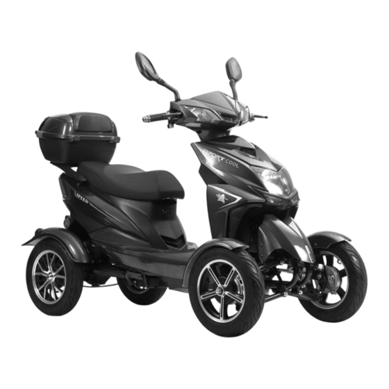
Recreational Mobility Scooter
MODEL: BL350-14
We continue to be committed to provide you tools with competitive price.
"Save Half", "Half Price" or any other similar expressions used by us only
represents an estimate of savings you might benefit from buying certain tools
with us compared to the major top brands and does not necessarily mean to
cover all categories of tools offered by us. You are kindly reminded to verify
carefully when you are placing an order with us if you are actually saving half
in comparison with the top major brands.
Advertisement

Related Manuals for VEVOR BL350-14


Summary of Contents for VEVOR BL350-14
- Page 1 Technical Support and E-Warranty Certificate www.vevor.com/support Recreational Mobility Scooter MODEL: BL350-14 We continue to be committed to provide you tools with competitive price. "Save Half", "Half Price" or any other similar expressions used by us only represents an estimate of savings you might benefit from buying certain tools with us compared to the major top brands and does not necessarily mean to cover all categories of tools offered by us.
- Page 2 This is the original instruction, please read all manual instructions carefully before operating. VEVOR reserves a clear interpretation of our user manual. The appearance of the product shall be subject to the product you received. Please forgive us that we won't inform you again if there are any technology or software updates on our product.
- Page 3 Dear users: The electric vehicle produced by our company is a transportation vehicle with advanced technology at home and abroad, green environmental protection, low noise, simple operation and other characteristics. It has simple operation, safe and reliable (with brake power off, underpressure protection, overcurrent protection, soft start, electromagnetic brake) and other functions.
- Page 4 WARNING: Check before riding Please check before riding to assure safety driving. Battery power Turn on the switch,watch battery meter indicator,when it approaches the red mark position, vehicle should be charged. Warning: You should regularly check the tires and adjust tire pressure. Check after the tire cooled.
- Page 5 ● Warning: Electric scooter should be parked on solidity, flat ground; otherwise it may cause injury or vehicle consequences of dumping. Security highlights Lock the parking lock, take away the key. Power-off when leave. Select high-quality alarm system. The product is constantly being upgraded, and there will be no notification if there is any change SAVE THESE INSTRUCTIONS FCC Information...
- Page 6 Connect the product to an outlet on a circuit different from that to which the receiver is connected. Consult the dealer or an experienced radio/TV technician for assistance. PRODUCT PARAMETERS BL350-14 Model Product size(LxWxH) 1890x765x1150 mm Nominal voltage DC 48 V...
- Page 7 Electrical schematic diagram - 6 -...
- Page 8 Manipulative methods and considerations 1. Description of the manipulation section: The manipulated part is shown in Figure 1, left brake / 2, far and far light switch / 3, power display / 4, speed display / 5, right brake / 6, knob / 7 headlight switch / 8, electric door lock / 9, horn switch / 10, turn signal switch.
- Page 9 1.5 Speedometer (3): Show the driving speed when driving. 1.6 Power indicator (4): it is a capacity indicator showing the presence of the battery. When the power door lock is in the "ON" position, the power pointer on the instrument is rotated to the corresponding position. During driving, the power is indicated at the H position, indicating that the battery is sufficient;...
- Page 10 2.3 Brake: When tightening the front and rear wheel handles, the front and rear wheels can be brake respectively.(Left is the rear brake, right is the front brake) 2.4 Parking: A. Should use the turn signal in advance to signal, inform other vehicles, pedestrians to attract attention, and then gradually drive to the roadside;...
- Page 11 3. Otherwise, it may be regarded as a partial fault of the speed regulator or the controller; 4. Motor fault. 1. Check whether the speed regulator is damaged; Release the speed handle 2, the line plug-in (line) contact disorder; and power the motor 3.
- Page 12 5. Instant power failure state processing: There are many reasons for instant power failure, mainly may be poor contact or brake power switch failure. On the one hand, the user can check the after-sales service, on the other hand, the user can self-check the following points. A.
- Page 13 Assembly instructions step1. install the front wheel, 1.1.Put the bracket under the frame 1.2. As shown in the arrow, set the pull rod corresponding to the specified position, release the screw, install the pull rod, and tighten the screw - 12 -...
- Page 14 1.3.As shown in Figure 1, release the screw,figure2, the side of the tyre in the arrow direction is outside the car, as shown in Figure 3, note the stuck position shown by the arrow, install the tyre, Figure 4, tighten the screw.the other side as same.
- Page 15 Step2 1.1.As shown in the figure 1 and 2, release the screws, install the PLASTIC PARTS 1, tighten the screws, As shown in Figure 3 and 4, release the screw, install the dashboard, and tighten the screws,the other side as same. - 14 -...
- Page 16 Step3 3.1.Installation instructions for the front section, As shown in Figure 1, loosen the screw, as shown in Figure 2, install the wheel head on the axle,pay attention to the point of the hole, In Figure 3, arrange the screw, as shown in Figure 4, tighten the screw with a socket wrench - 15 -...
- Page 17 3.2.As shown in Figure 1, the back of the wheel head, the screws on both sides are tightened, see Figure 2, the rearview mirror is installed at the aligned hole position, see Figure 3, tighten the screw with a wrench, see Figure 4, install PLASTIC part 2, align with the hole position, push up.
- Page 18 Maintenance The maintenance is important to electric scooter, if drive at high speed in a bad situation for a long time,must add the times of maintenance; If electric scooter have a big failure or have an accident,must check for mainly spare parts. For example: frame, indicator parts and soon.Repair or change the worn parts to make sure safety.
- Page 19 Often driving on uneven roads,in order to hold the good performance of your vehicle, it must be maintained. Maintenance for battery If the vehicle will not use for a long time, please take out the battery, full charge and store it in a cool, well ventilated and dry place. If the head of battery was corroded, please take out the battery and clean it.
- Page 20 Technical Support and E-Warranty Certificate www.vevor.com/support...
Need help?
Do you have a question about the BL350-14 and is the answer not in the manual?
Questions and answers
Where's the governor (speed controller) on the vevor BL350-14 mobility scooter
The governor (speed controller) on the VEVOR BL350-14 mobility scooter is located on the right side of the handle.
This answer is automatically generated
Battery use with details
Missing part that attachment to handle bar & axle BL 350-14 vevor