
Subscribe to Our Youtube Channel
Related Manuals for Endress+Hauser Proline Promass S 100


Summary of Contents for Endress+Hauser Proline Promass S 100
- Page 1 Products Solutions Services BA01060D/06/EN/04.24-00 71674303 2024-11-01 Valid as of version 01.03.zz (Device firmware) Operating Instructions Proline Promass S 100 Coriolis flowmeter Modbus RS485...
- Page 2 • The manufacturer reserves the right to modify technical data without prior notice. Your Endress+Hauser sales organization will supply you with current information and updates to this manual. Endress+Hauser...
- Page 3 Proline Promass S 100 Modbus RS485 Table of contents Table of contents Installing the measuring instrument ..23 About this document ....6 6.2.1...
- Page 4 10.5.3 Carrying out a sensor adjustment ..60 13.3 Endress+Hauser services ....86 10.5.4 Configuring the totalizer ..64 10.5.5 Using parameters for device...
- Page 5 Proline Promass S 100 Modbus RS485 Table of contents Index ....... . . 113...
- Page 6 About this document Proline Promass S 100 Modbus RS485 About this document Document function These Operating Instructions contain all the information required in the various life cycle phases of the device: from product identification, incoming acceptance and storage, to installation, connection, operation and commissioning, through to troubleshooting, maintenance and disposal.
- Page 7 For an overview of the scope of the associated Technical Documentation, refer to the following: • Device Viewer (www.endress.com/deviceviewer): Enter the serial number from the nameplate • Endress+Hauser Operations app: Enter serial number from nameplate or scan matrix code on nameplate. Endress+Hauser...
- Page 8 About this document Proline Promass S 100 Modbus RS485 The following documentation may be available depending on the device version ordered: Document type Purpose and content of the document Technical Information (TI) Planning aid for your device The document contains all the technical data on the device and provides an overview of the accessories and other products that can be ordered for the device.
- Page 9 Proline Promass S 100 Modbus RS485 Safety instructions Safety instructions Requirements for the personnel The personnel for installation, commissioning, diagnostics and maintenance must fulfill the following requirements: ‣ Trained, qualified specialists must have a relevant qualification for this specific function and task.
- Page 10 Verification for borderline cases: ‣ For special fluids and fluids for cleaning, Endress+Hauser is glad to provide assistance in verifying the corrosion resistance of fluid-wetted materials, but does not accept any warranty or liability as minute changes in the temperature, concentration or level of contamination in the process can alter the corrosion resistance properties.
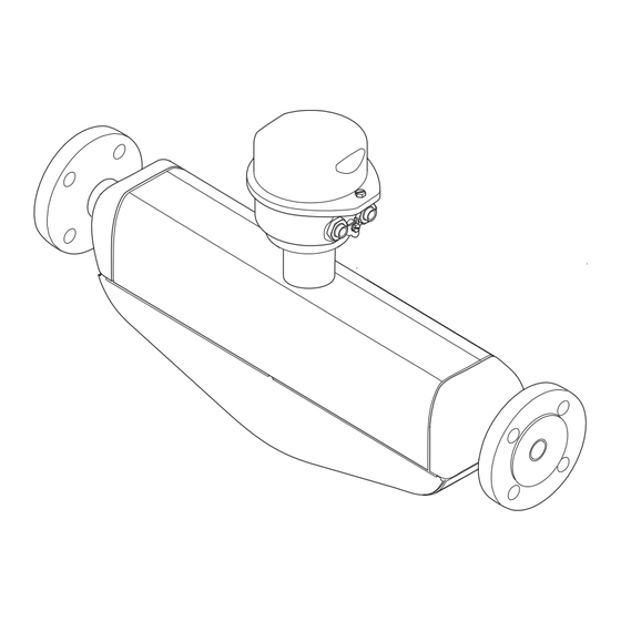
- Page 11 Proline Promass S 100 Modbus RS485 Product description Product description The device consists of a transmitter and a sensor. The Safety Barrier Promass 100 is part of the scope of supply and must be implemented to operate the device. The device is available as a compact version: The transmitter and sensor form a mechanical unit.
- Page 12 • Enter the serial numbers from the nameplates in the Device Viewer (www.endress.com/deviceviewer): all the information about the device is displayed. • Enter the serial numbers from the nameplates into the Endress+Hauser Operations app or scan the DataMatrix code on the nameplate with the Endress+Hauser Operations app: all the information about the device is displayed.
- Page 13 Proline Promass S 100 Modbus RS485 Incoming acceptance and product identification 4.2.1 Transmitter nameplate Order code: Ser. no.: Ext. ord. cd.: A0030222 2 Example of a transmitter nameplate Manufacturer address/certificate holder Name of the transmitter Order code Serial number Extended order code Electrical connection data, e.g.
- Page 14 Incoming acceptance and product identification Proline Promass S 100 Modbus RS485 4.2.2 Sensor nameplate Order code: Ser. no.: Ext. ord. cd.: Date: A0029199 3 Example of a sensor nameplate Name of the sensor Manufacturer address/certificate holder Order code Serial number (Ser. no.) Extended order code (Ext.
- Page 15 Proline Promass S 100 Modbus RS485 Incoming acceptance and product identification 4.2.3 Promass 100 safety barrier nameplate Safe area NON intrinsically safe circuit (grey terminals) Promass 100 Safety Barrier Intrinsically safe circuits (blue terminals) HAZARDOUS area A0017854 4 Example of a Promass 100 safety barrier nameplate Non-hazardous area or Zone 2/Div.
- Page 16 Storage and transport Proline Promass S 100 Modbus RS485 Storage and transport Storage conditions Observe the following notes for storage: ‣ Store in the original packaging to ensure protection from shock. ‣ Do not remove protective covers or protective caps installed on process connections.
- Page 17 Proline Promass S 100 Modbus RS485 Storage and transport 5.2.2 Measuring devices with lifting lugs CAUTION Special transportation instructions for devices with lifting lugs ‣ Only use the lifting lugs fitted on the device or flanges to transport the device.
- Page 18 Installation Proline Promass S 100 Modbus RS485 Installation Installation requirements 6.1.1 Installation position Installation point A0028772 To prevent measuring errors arising from accumulation of gas bubbles in the measuring pipe, avoid the following mounting locations in the piping: • Highest point of a pipeline.
- Page 19 Proline Promass S 100 Modbus RS485 Installation Ø orifice plate, pipe restriction [mm] [in] [mm] [in] ³⁄₈ 0.24 ½ 0.40 0.55 1 ½ 0.87 1.10 Orientation The direction of the arrow on the sensor nameplate helps you to install the sensor according to the flow direction (direction of medium flow through the piping).
- Page 20 Installation Proline Promass S 100 Modbus RS485 Inlet and outlet runs No special precautions need to be taken for fittings that create turbulence, such as valves, elbows or T-pieces, as long as no cavitation occurs → 20. A0029322 A0029323 Installation dimensions For the dimensions and installation lengths of the device, see the "Technical...
- Page 21 Proline Promass S 100 Modbus RS485 Installation The following device versions are recommended for versions with thermal insulation: Version with extended neck for insulation: Order code for "Sensor option", option CG with an extended neck length of 105 mm (4.13 in).
- Page 22 Installation Proline Promass S 100 Modbus RS485 Vibrations The high oscillation frequency of the measuring tubes ensures that the correct operation of the measuring system is not influenced by plant vibrations. 6.1.3 Special installation instructions Drainability When installed vertically, the measuring tubes can be drained completely and protected against buildup.
- Page 23 Proline Promass S 100 Modbus RS485 Installation To get a representative zero point, ensure that: • any flow in the device is prevented during the adjustment • the process conditions (e.g. pressure, temperature) are stable and representative Verification and adjustment cannot be carried out if the following process conditions are present: •...
- Page 24 Installation Proline Promass S 100 Modbus RS485 Post-installation check Is the device undamaged (visual inspection)? Does the measuring instrument correspond to the measuring point specifications? For example: • Process temperature → 101 • Pressure (refer to the "Pressure-temperature ratings" section of the "Technical Information"...
- Page 25 Proline Promass S 100 Modbus RS485 Electrical connection Electrical connection WARNING Live parts! Incorrect work performed on the electrical connections can result in an electric shock. ‣ Set up a disconnecting device (switch or power-circuit breaker) to easily disconnect the device from the supply voltage.
- Page 26 Electrical connection Proline Promass S 100 Modbus RS485 Connecting cable between Safety Barrier Promass 100 and measuring device Cable type Shielded twisted-pair cable with 2x2 wires. When grounding the cable shield, observe the grounding concept of the plant. Maximum cable resistance 2.5 Ω, one side Comply with the maximum cable resistance specifications to ensure the operational reliability of the measuring device.
- Page 27 Proline Promass S 100 Modbus RS485 Electrical connection Connection methods available Order code Possible options for order code Power "Housing" "Electrical connection" Output supply Options Device plugs Device plugs Option Q: 2 x plug M12x1 A, B, C → 29 →...
- Page 28 Electrical connection Proline Promass S 100 Modbus RS485 72 A A0030219 9 Modbus RS485 terminal assignment, connection version for use in intrinsically safe areas (connection via Safety Barrier Promass 100) Intrinsically safe power supply Modbus RS485 Order code 10 (L+)
- Page 29 Proline Promass S 100 Modbus RS485 Electrical connection 7.2.4 Pin assignment, device plug Supply voltage Promass 100 Device plug for signal transmission with supply voltage (device side), MODBUS RS485 (intrinsically safe) Assignment Supply voltage, intrinsically safe Modbus RS485 intrinsically safe...
- Page 30 Electrical connection Proline Promass S 100 Modbus RS485 7.2.5 Shielding and grounding Shielding and grounding concept 1. Maintain electromagnetic compatibility (EMC). 2. Take explosion protection into consideration. 3. Pay attention to the protection of persons. 4. Comply with national installation regulations and guidelines.
- Page 31 Proline Promass S 100 Modbus RS485 Electrical connection 7.3.1 Connecting the transmitter The connection of the transmitter depends on the following order codes: • Housing version: compact or ultra-compact • Connection version: device plug or terminals A0016924 11 Housing versions and connection versions...
- Page 32 Electrical connection Proline Promass S 100 Modbus RS485 For device version with device plug: follow step 6 only. 1. Depending on the housing version, loosen the securing clamp or fixing screw of the housing cover. 2. Depending on the housing version, unscrew or open the housing cover.
- Page 33 Proline Promass S 100 Modbus RS485 Electrical connection Potential equalization 7.4.1 Requirements For potential equalization: • Pay attention to in-house grounding concepts • Take account of operating conditions, such as the pipe material and grounding • Connect the medium, sensor and transmitter to the same electric potential •...
- Page 34 Electrical connection Proline Promass S 100 Modbus RS485 Modbus RS485 intrinsically safe L- L+ A0028766 15 Connection example for Modbus RS485 intrinsically safe Control system (e.g. PLC) Cable shield provided at one end. Observe cable specifications Safety Barrier Promass 100...
- Page 35 Proline Promass S 100 Modbus RS485 Electrical connection If the transmitter is used in the intrinsically safe area 220 Ω 27 A A0030217 17 Terminating resistor can be enabled via DIP switch in the Safety Barrier Promass 100 Ensuring the degree of protection The measuring instrument fulfills all the requirements for the degree of protection IP66/67, Type 4X enclosure.
- Page 36 Electrical connection Proline Promass S 100 Modbus RS485 Are all cable glands installed, securely tightened and leak-tight? Cable run with "water trap" → 35? Depending on the device version: Are all connectors securely tightened → 31? •...
- Page 37 Proline Promass S 100 Modbus RS485 Operation options Operation options Overview of operation options A0017760 Computer with "FieldCare" or "DeviceCare" operating tool via Commubox FXA291 and service interface Automation system (e.g. PLC) Endress+Hauser...
- Page 38 Operation options Proline Promass S 100 Modbus RS485 Structure and function of the operating menu 8.2.1 Structure of the operating menu For an overview of the operating menu for experts: see the "Description of Device Parameters" document supplied with the device → 111...
- Page 39 Proline Promass S 100 Modbus RS485 Operation options 8.2.2 Operating philosophy The individual parts of the operating menu are assigned to certain user roles (e.g. operator, maintenance etc.). Each user role contains typical tasks within the device life cycle. Menu/parameter...
- Page 40 Operation options Proline Promass S 100 Modbus RS485 X X X X X X X 1120.50 kg/h A0037831 Operational display Tag name Status area Display area for measured values (4-line) Status area The following symbols appear in the status area of the operational display at the top right: •...
- Page 41 Proline Promass S 100 Modbus RS485 Operation options Totalizer The measurement channel number indicates which of the three totalizers is displayed. Output Measurement channel numbers Symbol Meaning Measurement channel 1 to 4 The measurement channel number is displayed only if more than one channel is present for the same measured variable type (e.g.
- Page 42 FieldCare Function range FDT-based (Field Device Technology) plant asset management tool from Endress+Hauser. It can configure all smart field units in a system and helps you manage them. By using the status information, it is also a simple but effective way of checking their status and condition.
- Page 43 DeviceCare Function range Tool for connecting and configuring Endress+Hauser field devices. The fastest way to configure Endress+Hauser field devices is with the dedicated "DeviceCare" tool. Together with the device type managers (DTMs) it presents a convenient, comprehensive solution. Innovation brochure IN01047S Source for device description files →...
- Page 44 System integration Proline Promass S 100 Modbus RS485 System integration Overview of device description files 9.1.1 Current version data for the device Firmware version 01.03.zz • On the title page of the manual • On the transmitter nameplate • Firmware version Diagnostics →...
- Page 45 Proline Promass S 100 Modbus RS485 System integration Code Name Description Application Write single Master writes a new value to one Write only 1 device parameter registers Modbus register of the measuring Example: reset totalizer device. Use function code 16 to write multiple registers with just 1 telegram.
- Page 46 System integration Proline Promass S 100 Modbus RS485 INTEGER Data length = 2 bytes (1 register) Byte 1 Byte 0 Most significant byte (MSB) Least significant byte (LSB) STRING Data length = depends on the device parameter, e.g. presentation of a device parameter with a data length = 18...
- Page 47 Proline Promass S 100 Modbus RS485 System integration 0 – 1 – 2 – 3 Byte 16 Byte 17 Byte 0 Byte 1 2 – 3 – 0 – 1 (MSB) (LSB) * = factory setting, MSB = most significant byte, LSB = least significant byte 9.2.6...
- Page 48 System integration Proline Promass S 100 Modbus RS485 Configuration of the scan list via Modbus RS485 Carried out using register addresses 5001 - 5016 Scan list Modbus RS485 register Data type Configuration register 5001 Integer Scan list register 0 Integer...
- Page 49 Proline Promass S 100 Modbus RS485 Commissioning Commissioning 10.1 Post-mounting and post-connection check Before commissioning the device: ‣ Make sure that the post-installation and post-connection checks have been performed successfully. • Checklist for "Post-installation" check→ 24 • Checklist for "Post-connection" check→ 35 10.2...
- Page 50 Commissioning Proline Promass S 100 Modbus RS485 Navigation "Setup" menu → Device tag Parameter overview with brief description Parameter Description User entry Device tag Enter the name for the measuring point. Max. 32 characters, such as letters, numbers or special characters (e.g. @, %, /).
- Page 51 Proline Promass S 100 Modbus RS485 Commissioning Parameter overview with brief description Parameter Description Selection Factory setting Mass flow unit Select mass flow unit. Unit choose list Country-specific: • kg/h Effect • lb/min The selected unit applies to: • Output •...
- Page 52 Commissioning Proline Promass S 100 Modbus RS485 Parameter Description Selection Factory setting Temperature unit Select temperature unit. Unit choose list Country-specific: • °C Effect • °F The selected unit applies to: • Electronic temperature parameter (6053) • Maximum value parameter (6051) •...
- Page 53 Proline Promass S 100 Modbus RS485 Commissioning 10.4.3 Selecting and setting the medium The Select medium wizard submenu contains parameters that must be configured in order to select and set the medium. Navigation "Setup" menu → Medium selection ‣ Medium selection Select medium →...
- Page 54 Commissioning Proline Promass S 100 Modbus RS485 Parameter Prerequisite Description Selection / User entry Reference sound velocity In the Select gas type parameter, the Enter sound velocity of gas at 0 °C (32 1 to 99 999.9999 m/s Others option is selected.
- Page 55 Proline Promass S 100 Modbus RS485 Commissioning Parameter Description User entry / Selection Data transfer mode Select data transfer mode. • ASCII • RTU Parity Select parity bits. Picklist ASCII option: • 0 = Even option • 1 = Odd option Picklist RTU option: •...
- Page 56 Commissioning Proline Promass S 100 Modbus RS485 10.4.5 Configuring the low flow cut off The Low flow cut off submenu contains the parameters that must be set in order to configure the low flow cut off. Navigation "Setup" menu → Low flow cut off ‣...
- Page 57 Proline Promass S 100 Modbus RS485 Commissioning 10.4.6 Configuring partially filled pipe detection The Partially filled pipe detection submenu contains parameters that have to be set for configuring empty pipe detection. Navigation "Setup" menu → Partially filled pipe detection ‣...
- Page 58 Commissioning Proline Promass S 100 Modbus RS485 10.5 Advanced settings The Advanced setup submenu with its submenus contains parameters for specific settings. The number of submenus can vary depending on the device version, e.g. viscosity is available only with the Promass I.
- Page 59 Proline Promass S 100 Modbus RS485 Commissioning "Corrected volume flow calculation" submenu Navigation "Setup" menu → Advanced setup → Calculated values → Corrected volume flow calculation ‣ Corrected volume flow calculation → 59 Corrected volume flow calculation (1812) External reference density (6198) →...
- Page 60 Commissioning Proline Promass S 100 Modbus RS485 Parameter Prerequisite Description Selection / User Factory setting interface / User entry Linear expansion coefficient The Calculated reference Enter linear, medium-specific 0 to 1 – density option is selected in expansion coefficient for the Corrected volume flow...
- Page 61 Proline Promass S 100 Modbus RS485 Commissioning Performing density adjustment Note the following before performing the adjustment: • A density adjustment only makes sense if there is little variation in the operating conditions and the density adjustment is performed under the operating conditions.
- Page 62 Commissioning Proline Promass S 100 Modbus RS485 4. Select the Measure density 1 option and confirm. In the Execute density adjustment parameter the following options are now available: Measure density 2 Restore original 5. Select the Measure density 2 option and confirm.
- Page 63 Proline Promass S 100 Modbus RS485 Commissioning Parameter Prerequisite Description Selection / User Factory setting entry / User interface Density setpoint 2 In the Density adjustment The entry depends on – mode parameter, the 2 point the unit selected in adjustment option is selected.
- Page 64 Commissioning Proline Promass S 100 Modbus RS485 Navigation "Setup" menu → Advanced setup → Sensor adjustment → Zero point adjustment ‣ Zero point adjustment Zero point adjustment control → 64 Progress → 64 Parameter overview with brief description...
- Page 65 Proline Promass S 100 Modbus RS485 Commissioning Parameter Prerequisite Description Selection Factory setting Totalizer operation mode A process variable is selected Select totalizer calculation • Net flow total – in the Assign process variable mode. • Forward flow total parameter (→ 64) of the •...
- Page 66 Commissioning Proline Promass S 100 Modbus RS485 Simulation device alarm → 66 Diagnostic event simulation Parameter overview with brief description Parameter Prerequisite Description Selection / User entry Assign simulation process variable – Select a process variable for the • Off simulation process that is activated.
- Page 67 Proline Promass S 100 Modbus RS485 Commissioning A0030224 Setting the write protection switch on the main electronics module to the On position enables hardware write protection. Setting the write protection switch on the main electronics module to the Off position (factory setting) disables hardware write protection.
- Page 68 Operation Proline Promass S 100 Modbus RS485 Operation 11.1 Reading the device locking status Device active write protection: Locking status parameter Navigation "Operation" menu → Locking status Function scope of "Locking status" parameter Options Description Hardware locked The locking switch (DIP switch) for locking the hardware is activated on the main electronic module.
- Page 69 Proline Promass S 100 Modbus RS485 Operation Volume flow → 69 Corrected volume flow → 69 → 69 Density Reference density → 69 Temperature → 70 Pressure → 70 → 70 Concentration Target mass flow →...
- Page 70 Operation Proline Promass S 100 Modbus RS485 Parameter Prerequisite Description User interface Measured values 6 – Signed floating-point number Pressure value – Displays either a fixed or external Signed floating-point pressure value. number Dependency The unit is taken from the Pressure unit parameter (→...
- Page 71 Proline Promass S 100 Modbus RS485 Operation Parameter overview with brief description Parameter Prerequisite Description User interface Totalizer value 1 to n One of the following options is selected Displays the current totalizer counter Signed floating-point in the Assign process variable value.
- Page 72 Operation Proline Promass S 100 Modbus RS485 Parameter overview with brief description Parameter Prerequisite Description Selection / User Factory setting entry / User interface Control Totalizer 1 to n A process variable is selected Control totalizer value. • Totalize – in the Assign process variable •...
- Page 73 Proline Promass S 100 Modbus RS485 Operation 11.5.2 Function range of "Reset all totalizers" parameter Options Description Cancel No action is executed and the user exits the parameter. Reset + totalize Resets all totalizers to 0 and restarts the totaling process. This deletes all the previously aggregated flow values.
- Page 74 Diagnostics and troubleshooting Proline Promass S 100 Modbus RS485 Diagnostics and troubleshooting 12.1 General troubleshooting For output signals Error Possible causes Remedial action Green power LED on the main electronics Supply voltage does not match the voltage Apply the correct supply voltage → 31.
- Page 75 Proline Promass S 100 Modbus RS485 Diagnostics and troubleshooting A0029689 Supply voltage Device status Not used Communication Service interface (CDI) active 1. Open the housing cover. 2. Remove the display module. 3. Fold open the terminal cover. Color Meaning Supply voltage...
- Page 76 Diagnostics and troubleshooting Proline Promass S 100 Modbus RS485 12.3 Diagnostic information in FieldCare or DeviceCare 12.3.1 Diagnostic options Any faults detected by the measuring device are displayed on the home page of the operating tool once the connection has been established.
- Page 77 Proline Promass S 100 Modbus RS485 Diagnostics and troubleshooting Diagnostic information The fault can be identified using the diagnostic information. The short text helps you by providing information about the fault. Diagnostic information Diagnostic code Status signal Diagnostic number Short text ↓...
- Page 78 Diagnostics and troubleshooting Proline Promass S 100 Modbus RS485 Parameter overview with brief description Parameter Description Options Factory setting Failure mode Select measured value • NaN value NaN value output behavior when a • Last valid value diagnostic message occurs ...
- Page 79 Proline Promass S 100 Modbus RS485 Diagnostics and troubleshooting Diagnostic Short text Remedy instructions Status Diagnostic number signal behavior [from the [from the factory] factory] Memory content 1. Restart device Alarm 2. Contact service Sensor signal 1. Check or change main...
- Page 80 Diagnostics and troubleshooting Proline Promass S 100 Modbus RS485 Diagnostic Short text Remedy instructions Status Diagnostic number signal behavior [from the [from the factory] factory] Diagnostic of process Sensor temperature too Reduce ambient temp. around the Warning high sensor housing Sensor temperature too Increase ambient temp.
- Page 81 Proline Promass S 100 Modbus RS485 Diagnostics and troubleshooting Navigation "Diagnostics" menu Diagnostics Actual diagnostics → 81 Previous diagnostics → 81 → 81 Operating time from restart Operating time → 81 Parameter overview with brief description...
- Page 82 Diagnostics and troubleshooting Proline Promass S 100 Modbus RS485 Navigation path Edit tool bar: F → Additional functions → Events list The edit tool bar can be accessed via the FieldCare user interface → 42 This event history includes entries for: •...
- Page 83 Proline Promass S 100 Modbus RS485 Diagnostics and troubleshooting Info number Info name I1221 Zero point adjust failure I1222 Zero point adjustment ok I1256 Display: access status changed I1335 Firmware changed I1397 Fieldbus: access status changed I1398 CDI: access status changed...
- Page 84 Diagnostics and troubleshooting Proline Promass S 100 Modbus RS485 12.11 Device information The Device information submenu contains all parameters that display different information for device identification. Navigation "Diagnostics" menu → Device information ‣ Device information Device tag → 84 Serial number →...
- Page 85 "Manufacturer' s information" document. The manufacturer' s information is available: • In the Download Area of the Endress+Hauser web site: www.endress.com → Downloads • Specify the following details: •...
- Page 86 Observe the inside diameter of the measuring tube and process connection. 13.2 Measuring and test equipment Endress+Hauser offers a variety of measuring and testing equipment, such as Netilion or device tests. Your Endress+Hauser Sales Center can provide detailed information on the services.
- Page 87 • The measuring devices have a modular design. • Spare parts are grouped into logical kits with the associated Installation Instructions. • Repairs are carried out by Endress+Hauser Service or by appropriately trained customers. • Certified devices can only be converted to other certified devices by Endress+Hauser Service or at the factory.
- Page 88 Repair Proline Promass S 100 Modbus RS485 14.5 Disposal If required by the Directive 2012/19/EU on waste electrical and electronic equipment (WEEE), the product is marked with the depicted symbol in order to minimize the disposal of WEEE as unsorted municipal waste. Do not dispose of products bearing this marking as unsorted municipal waste.
- Page 89 Various accessories, which can be ordered with the device or subsequently from Endress +Hauser, are available for the device. Detailed information on the order code in question is available from your local Endress+Hauser sales center or on the product page of the Endress+Hauser website: www.endress.com.
- Page 90 Via the Internet: https://portal.endress.com/webapp/applicator Netilion lloT ecosystem: Unlock knowledge With the Netilion IIoT ecosystem,Endress+Hauser allows you to optimize your plant performance, digitize workflows, share knowledge, and enhance collaboration. Drawing upon decades of experience in process automation, Endress+Hauser offers the process industry an IIoT ecosystem designed to effortlessly extract insights from data.
- Page 91 Proline Promass S 100 Modbus RS485 Accessories 15.4 System components Accessories Description Memograph M graphic The Memograph M graphic data manager provides information on all the relevant data manager measured variables. Measured values are recorded correctly, limit values are monitored and measuring points analyzed. The data are stored in the 256 MB internal memory and also on a SD card or USB stick.
- Page 92 Technical data Proline Promass S 100 Modbus RS485 Technical data 16.1 Application The measuring device is intended only for the flow measurement of liquids. Depending on the version ordered, the measuring device can also measure potentially explosive, flammable, poisonous and oxidizing media.
- Page 93 • Operating pressure to increase measurement accuracy (Endress+Hauser recommends the use of a pressure measuring instrument for absolute pressure, e.g. Cerabar M or Cerabar S) •...
- Page 94 Technical data Proline Promass S 100 Modbus RS485 16.4 Output Output signal Modbus RS485 Physical interface In accordance with EIA/TIA-485-A standard Terminating resistor • For device version used in non-hazardous areas or Zone 2/Div. 2: integrated and can be activated via DIP switches on the transmitter electronics module •...
- Page 95 Proline Promass S 100 Modbus RS485 Technical data Function codes • 03: Read holding register • 04: Read input register • 06: Write single registers • 08: Diagnostics • 16: Write multiple registers • 23: Read/write multiple registers Broadcast messages Supported by the following function codes: •...
- Page 96 Technical data Proline Promass S 100 Modbus RS485 Promass 100 safety barrier Maximum Order code for "Output" Power consumption Option M: Modbus RS485, for use in intrinsically safe areas 4.8 W Current consumption Transmitter Maximum Maximum Order code for "Output"...
- Page 97 Proline Promass S 100 Modbus RS485 Technical data 16.6 Performance characteristics Reference operating • Error limits based on ISO 11631 conditions • Water • +15 to +45 °C (+59 to +113 °F) • 2 to 6 bar (29 to 87 psi) •...
- Page 98 Technical data Proline Promass S 100 Modbus RS485 SI units 1:10 1:20 1:50 1:100 1:500 [mm] [kg/h] [kg/h] [kg/h] [kg/h] [kg/h] [kg/h] 2 000 6 500 18 000 1 800 45 000 4 500 2 250 70 000 7 000...
- Page 99 Proline Promass S 100 Modbus RS485 Technical data The influence is reduced when the zero adjustment is performed at process temperature. Density If there is a difference between the density calibration temperature and the process temperature, the measurement error of the sensors is typically ±0.0001 g/cm...
- Page 100 Technical data Proline Promass S 100 Modbus RS485 MeasValue = measured value; ZeroPoint = zero point stability Calculation of the maximum measured error as a function of the flow rate Flow rate Maximum measured error in % o.r. ZeroPoint ⋅...
- Page 101 Proline Promass S 100 Modbus RS485 Technical data Storage temperature –40 to +80 °C (–40 to +176 °F), preferably at +20 °C (+68 °F) (standard version) –50 to +80 °C (–58 to +176 °F) (Order code for "Test, certificate", option JM)
- Page 102 Technical data Proline Promass S 100 Modbus RS485 Pressure-temperature For an overview of the pressure-temperature ratings for the process connections, see ratings the Technical Information Sensor housing The sensor housing is filled with dry nitrogen gas and protects the electronics and mechanics inside.
- Page 103 Proline Promass S 100 Modbus RS485 Technical data Pressure loss To calculate the pressure loss, use the Applicator sizing tool → 90 System pressure → 20 Endress+Hauser...
- Page 104 Technical data Proline Promass S 100 Modbus RS485 16.10 Mechanical construction Design, dimensions For the dimensions and installation lengths of the device, see the "Technical Information" document, "Mechanical construction" section Weight All values (weight exclusive of packaging material) refer to devices with EN/DIN PN 40 flanges.
- Page 105 Proline Promass S 100 Modbus RS485 Technical data Cable entries/cable glands A0020640 19 Possible cable entries/cable glands Female thread M20 × 1.5 Cable gland M20 × 1.5 Adapter for cable entry with female thread G ½" or NPT ½"...
- Page 106 Technical data Proline Promass S 100 Modbus RS485 Process connections Flange according to EN Stainless steel, 1.4404 (F316/F316L) 1092-1 (DIN 2501)/ASME B16.5/JIS B2220: All other process Stainless steel, 1.4435 (316L) connections: Available process connections→ 106 Seals Welded process connections without internal seals...
- Page 107 The device meets the legal requirements of the applicable EU Directives. These are listed in the corresponding EU Declaration of Conformity along with the standards applied. Endress+Hauser confirms successful testing of the device by affixing to it the CE mark. UKCA marking The device meets the legal requirements of the applicable UK regulations (Statutory Instruments).
- Page 108 Directive a) PED/G1/x (x = category) or b) PESR/G1/x (x = category) on the sensor nameplate, Endress+Hauser confirms compliance with the "Essential Safety Requirements" a) specified in Annex I of the Pressure Equipment Directive 2014/68/EU or b) Schedule 2 of Statutory Instruments 2016 No. 1105.
- Page 109 The application packages can be ordered with the device or subsequently from Endress+Hauser. Detailed information on the order code in question is available from your local Endress+Hauser sales center or on the product page of the Endress+Hauser website: www.endress.com.
- Page 110 Technical data Proline Promass S 100 Modbus RS485 Heartbeat Verification Meets the requirement for traceable verification to DIN ISO 9001:2008 Chapter 7.6 a) "Control of monitoring and measuring equipment". • Functional testing in the installed state without interrupting the process.
- Page 111 For an overview of the scope of the associated Technical Documentation, refer to the following: • Device Viewer (www.endress.com/deviceviewer): Enter the serial number from the nameplate • Endress+Hauser Operations app: Enter serial number from nameplate or scan matrix code on nameplate. Standard documentation Brief Operating instructions...
- Page 112 Technical data Proline Promass S 100 Modbus RS485 Installation instructions Contents Note Installation instructions for spare part sets and • Access the overview of all the available spare part accessories sets via Device Viewer → 87 • Accessories available for order with Installation Instructions →...
- Page 113 Proline Promass S 100 Modbus RS485 Index Index 0 … 9 Operating menu ......38 Design fundamentals 3-A approval .
- Page 114 Index Proline Promass S 100 Modbus RS485 Events list ....... . . 81 Local display Ex-approval .
- Page 115 Proline Promass S 100 Modbus RS485 Index Inlet and outlet runs ..... . . 20 Post-connection check ......49 Installation dimensions .
- Page 116 Index Proline Promass S 100 Modbus RS485 Totalizer reset ......71 Terminals ....... . . 96 Shock and vibration resistance .
- Page 118 *71674303* 71674303 www.addresses.endress.com...
Need help?
Do you have a question about the Proline Promass S 100 and is the answer not in the manual?
Questions and answers