Advertisement
Quick Links
TECHNICAL & SERVICE MANUAL
Indoor unit
[Model names]
PCFY-MS40VKM-E
PCFY-MS40VKM-ET
PCFY-MS63VKM-E
PCFY-MS63VKM-ET
PCFY-MS100VKM-E
PCFY-MS100VKM-ET
PCFY-MS125VKM-E
PCFY-MS125VKM-ET
INDOOR UNIT
[Service Ref.]
PCFY-MS40VKM-E
PCFY-MS40VKM-ET
PCFY-MS63VKM-E
PCFY-MS63VKM-ET
PCFY-MS100VKM-E
PCFY-MS100VKM-ET
PCFY-MS125VKM-E
PCFY-MS125VKM-ET
Model name
indication
R32
Note:
• This manual describes only
service data of the indoor units.
CONTENTS
1. SAFETY PRECAUTION ······················· 2
2. PART NAMES AND FUNCTIONS ·········· 8
3. SPECIFICATION ································ 9
4. OUTLINES AND DIMENSIONS ··········· 13
5. WIRING DIAGRAM ··························· 16
6. REFRIGERANT SYSTEM DIAGRAM ··· 17
7. TROUBLESHOOTING ······················· 18
8. DISASSEMBLY PROCEDURE ············ 27
9. REMOTE CONTROLLER ··················· 33
PARTS CATALOG (OCB820)
July 2023
No. OCH820
Advertisement

Related Manuals for Mitsubishi Electric CITI MULTI PCFY Series


Summary of Contents for Mitsubishi Electric CITI MULTI PCFY Series
- Page 1 July 2023 No. OCH820 TECHNICAL & SERVICE MANUAL Indoor unit [Model names] [Service Ref.] PCFY-MS40VKM-E PCFY-MS40VKM-E Note: PCFY-MS40VKM-ET PCFY-MS40VKM-ET • This manual describes only service data of the indoor units. PCFY-MS63VKM-E PCFY-MS63VKM-E PCFY-MS63VKM-ET PCFY-MS63VKM-ET PCFY-MS100VKM-E PCFY-MS100VKM-E PCFY-MS100VKM-ET PCFY-MS100VKM-ET PCFY-MS125VKM-E PCFY-MS125VKM-E PCFY-MS125VKM-ET PCFY-MS125VKM-ET CONTENTS...
- Page 2 SAFETY PRECAUTION MEANINGS OF SYMBOLS DISPLAYED ON THE UNIT This mark is for R32 refrigerant only. Refrigerant type is written on nameplate of outdoor unit. WARNING Read the OPERATION MANUAL carefully before operation. Service personnel are required to carefully read the OPERATION MANUAL and INSTALLATION MANUAL before operation. Further information is available in the OPERATION MANUAL, INSTALLATION MANUAL, and the like.
- Page 3 [1] Warning for service (1) Do not alter the unit. (2) For installation and relocation work, follow the instructions in the Installation Manual and use tools and pipe components specifically made for use with refrigerant specified in the outdoor unit installation manual. (3) Ask a dealer or an authorized technician to install, relocate and repair the unit.
- Page 4 [4] Cautions for unit using R32 refrigerant Basic work procedures are the same as those for conventional units using refrigerant R410A. However, pay careful attention to the following points. (1) Information on servicing (1-1) Checks on the Area Prior to beginning work on systems containing flammable refrigerants, safety checks are necessary to ensure that the risk of ignition is minimized.
- Page 5 (3) Repair to intrinsically Safe Components Do not apply any permanent inductive or capacitance loads to the circuit without ensuring that this will not exceed the permissible voltage and current permitted for the equipment in use. Intrinsically safe components are the only types that can be worked on while live in the presence of a flammable atmos- phere.
- Page 6 a) Become familiar with the equipment and its operation. b) Isolate system electrically. c) Before attempting the procedure, ensure that: • mechanical handling equipment is available, if required, for handling refrigerant cylinders; • all personal protective equipment is available and being used correctly; •...
- Page 7 Unit Electronic weighing scale [5] Service tools Use the below service tools as exclusive tools for R32 refrigerant. Refer to the sepec name plate on outdoor unit for the type of refrigerant being used. Tool name Specifications · Use the existing fitting specifications . (UNF1/2) Gauge manifold ·...
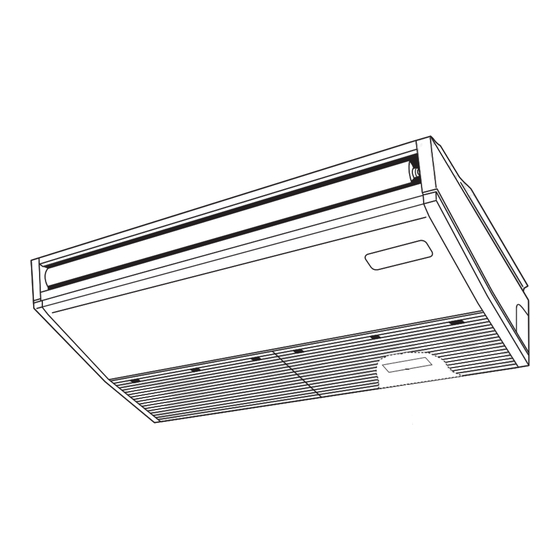
- Page 8 PART NAMES AND FUNCTIONS 2-1. INDOOR UNIT Louver Air outlet Vane Filter Air intake (Inside of Air intake) OCH820...
- Page 9 SPECIFICATION 3-1. SPECIFICATIONS Model PCFY-MS40VKM-E/ET PCFY-MS63VKM-E/ET PCFY-MS100VKM-E/ET PCFY-MS125VKM-E/ET 1-phase 220-240V 50Hz , 1-phase 220V 60Hz Power source Cooling capacity *1 kW 11.2 14.0 ( Nominal ) *1 kcal/h 3 , 900 6 , 100 9 , 600 12 , 000 *1 Btu/h 15 , 400 24 , 200...
- Page 10 3-2. ELECTRICAL PARTS SPECIFICATIONS Service Ref. PCFY-MS100VKM-E PCFY-MS40VKM-E PCFY-MS63VKM-E PCFY-MS100VKM-ET Symbol PCFY-MS40VKM-ET PCFY-MS63VKM-ET PCFY-MS125VKM-E PCFY-MS125VKM-ET Parts name Room temperature TH21 Resistance 0°C/15 kΩ, 10°C/9.6 kΩ, 20°C/6.3 kΩ, 25°C/5.4 kΩ, 30°C/4.3 kΩ, 40°C/3.0 kΩ thermistor Liquid pipe thermistor TH22 Resistance 0°C/15 kΩ, 10°C/9.6 kΩ, 20°C/6.3 kΩ, 25°C/5.4 kΩ, 30°C/4.3 kΩ, 40°C/3.0 kΩ Gas pipe thermistor TH23 Resistance 0°C/15 kΩ, 10°C/9.6 kΩ, 20°C/6.3 kΩ, 25°C/5.4 kΩ, 30°C/4.3 kΩ, 40°C/3.0 kΩ...
- Page 11 3-4. NC CURVES PCFY-MS40VKM-E PCFY-MS63VKM-E PCFY-MS40VKM-ET PCFY-MS63VKM-ET External static pressure : 0 Pa External static pressure : 0 Pa Power source : 220, 230, 240 V, 50 Hz / 220 V, 60 Hz Power source : 220, 230, 240 V, 50 Hz / 220 V, 60 Hz High Middle2 High...
- Page 12 3-5. FRESH AIR INTAKE AMOUNT & STATIC PRESSURE CHARACTERISTICS PCFY-MS63VKM-E PCFY-MS40VKM-E PCFY-MS63VKM-ET PCFY-MS40VKM-ET -100 -100 -150 -150 -200 -200 -250 -250 -300 -300 Airflow rate[m³/min] Airflow rate[m³/min] PCFY-MS100/125VKM-E How to read curves PCFY-MS100/125VKM-ET Duct characteristics Curve in the at site graphs Q …...
- Page 13 OUTLINES AND DIMENSIONS PCFY-MS40VKM-E Unit : mm PCFY-MS40VKM-ET OCH820...
- Page 14 Unit : mm PCFY-MS63VKM-E PCFY-MS63VKM-ET OCH820...
- Page 15 Unit : mm PCFY-MS100VKM-E PCFY-MS125VKM-E PCFY-MS100VKM-ET PCFY-MS125VKM-ET OCH820...
- Page 16 WIRING DIAGRAM OCH820...
- Page 17 REFRIGERANT SYSTEM DIAGRAM Refrigerant flow in cooling Refrigerant flow in heating Gas pipe thermistor TH23 Strainer (#50 mesh) Gas pipe Flare connection Liquid pipe thermistor TH22 Liquid pipe Heat exchanger Linear expansion valve Strainer1 (#50 mesh) Strainer2 (#100 mesh) Strainer (#100 mesh) Room temparature thermistor TH21 Unit : mm (in) Service Ref.
- Page 18 TROUBLESHOOTING 7-1. COUNTERMEASURES FOR ERROR DURING TEST RUN If a problem occurs during test run, a code number will appear on the remote controller (or LED on the outdoor unit), and the air conditioning system will automatically cease operating. Refer to the connected outdoor unit service manual in order to determine the nature of the abnormality and apply corrective measure.
- Page 19 7-2. HOW TO CHECK THE PARTS Parts name Checkpoints Room temperature Disconnect the connector then measure the resistance with a tester. thermistor (TH21) (At the ambient temperature of 10°C~30°C) Liquid pipe thermistor (TH22) Normal Abnormal (Refer to Thermistor characteristic graph.) Gas pipe thermistor 4.3 kΩ~9.6 kΩ...
- Page 20 7-2-1. Thermistor <Thermistor characteristic graph> < Thermistor for lower temperature > Thermistors for Room temperature thermistor (TH21) lower temperature Liquid pipe temperature thermistor (TH22) Gas pipe temperature thermistor (TH23) Thermistor R =15 kΩ ± 3% Fixed number of B=3480 ± 2% Rt=15exp { 3480 ( 273+t 0°C...
- Page 21 <Output pulse signal and the valve operation> Output Output The output pulse shifts in the following order. (Phase) Closing a valve : 1 → 2 → 3 → 4 → 1 Opening a valve : 4 → 3 → 2 → 1 → 4 ø1 Note: ø2...
- Page 22 7-2-3. DC Fan motor (fan motor/indoor controller circuit board) Check method of DC fan motor (fan motor/indoor controller circuit board) Notes · High voltage is applied to the connector (CNMF) for the fan motor. Pay attention to the service. · Do not pull out the connector (CNMF) for the motor with the power supply on. (It causes trouble of the indoor controller board and fan motor.) Self check Symptom : The indoor fan cannot turn around.
- Page 23 7-3. FUNCTION OF DIP SWITCH ■ The black square ( ) indicates a switch position. Operation by switch Effective Switch Pole Function Remarks timing Thermistor <Room temperature <Initial setting> Built-in remote controller Indoor unit detection> position Filter clogging detection Provided Not provided 1 2 3 4 5 6 7 8 9 10 Note :...
- Page 24 Switch Pole Function Operation by switch Effective Remarks timing SW11 How to set address <Initial setting> 1s digit Example : If address is "3", remain SW12 SW12 SW11 SW12 SW11 address (for over 10) at "0", and match SW11 (for 1 to 9) setting with "3".
- Page 25 ■ The black square ( ) indicates a switch position. Operation by switch Effective Switch Pole Function Remarks timing <Initial setting> Setting the ceiling height Depending on the combination of SW21-1 and SW21-2. Setting the ceiling height SW21 Not used Not used Not used Under...
- Page 26 7-4. TEST POINT DIAGRAM Indoor controller board CN3M Connect to the terminal block (TB5) (M-NET transmission connecting wire) CN2A : 24-30 VDC (non-polar) Connect to the terminal block (TB15) (MA-Remote controller connecting wire) SW21 - : 8.7-13 VDC (non-polar) Function setting LED2 Vane motor output Power supply for...
- Page 27 DISASSEMBLY PROCEDURE Be careful when removing heavy parts. (Photo: PCFY-MS125VKM-E) : Indicates the visible parts in the photos/figures. OPERATING PROCEDURE PHOTOS/FIGURES Figure 1 1. Removing the air intake grille (1) Slide the air intake grille holding knobs (at 2 or 3 loca- tions) to the rear to open the air intake grille.
- Page 28 OPERATING PROCEDURE PHOTOS/FIGURES 3. Removing the room temperature thermistor (TH21) Photo 4 Casing (1) Remove the air intake grille. (See Figure 1, 2) (2) Remove the screw from the beam and remove the beam. (See Photo 1) (3) Remove 2 screws from the electrical cover, and remove the electrical cover.
- Page 29 OPERATING PROCEDURE PHOTOS/FIGURES 5. Removing the fan (3 connection) Photo 9 Beam Fan guard (1) Remove the air intake grille. (See Figure 1, 2) (2) Remove the screw from the beam and remove the beam. (See Photo 1) (3) Remove 2 screws from the electrical cover, and remove the electrical cover.
- Page 30 OPERATING PROCEDURE PHOTOS/FIGURES Photo 13 7-1. Removing the vane motor Screw of R32 sensor (1) Remove the air intake. (See Figure 1, 2) Connector Vane motor R32 sensor of vane motor (2) Remove the right side panel. (See Figure 3) and cover (3) Remove the connector of vane motor.
- Page 31 OPERATING PROCEDURE PHOTOS/FIGURES Photo 18 10. Removing the pipe thermistors / Liquid (TH22) and Gas (TH23) (1) Remove the air intake grille. (See Figure 1, 2) (2) Remove the left and right side panels. (See Figure 3) (3) Remove the under panel. (See Photo 14) (4) Remove the drain pan.
- Page 32 OPERATING PROCEDURE PHOTOS/FIGURES Photo 22 13. Removing the heat exchanger, LEV and LEV coil (1) Remove the air intake grille. (See Figure 1, 2) (2) Remove the beam. (See Photo 1) (3) Remove the electrical cover. (See Photo 1) (4) Pull the electrical box downward. (See Photo 2) (5) Disconnect the connector CN60 from the indoor con- troller board.
- Page 33 REMOTE CONTROLLER 9-1. REMOTE CONTROLLER FUNCTIONS <PAR-41MAAB> Controller interface The functions of the function buttons change depending on the screen. Refer to the button function guide that appears at the bottom of the LCD for the functions they serve on a given screen. When the system is centrally controlled, the button function guide that corresponds to the locked button will not appear.
- Page 34 Display The main display can be displayed in two different modes: ˝Full˝ and ˝Basic˝. The initial setting is ˝Full˝. To switch to the ˝Basic˝ mode, change the setting on the Main display setting. (Refer to operation manual included with remote controller.) <Full mode>...
- Page 35 Menu structure Main menu Press the button. Move the cursor to the desired item with the buttons, and press the button. Operation Vane · 3D i-see · Vent. (Lossnay) High power Comfort Manual vane angle Vertical air direction Horizontal air direction 3D i-see Sensor Timer menu Timer...
- Page 36 Continue from the previous page. Maintenance menu Error information Filter information Cleaning Auto descending panel Descending operation Descending adjustment Service menu Test run menu Test run Drain pump test run Refrigerant system check Maintenance information Collect model names and serial No. Model name input Serial No.
- Page 37 Main menu list Main Setting and display items Setting details menu Operation Vane · 3D i-see · Vent. Vane: Use to set the vertical air direction. (Vane.Vent. (Lossnay)) Louver: Use to set the horizontal air direction. 3D i-see Sensor: This setting is available only for the air conditioners that support easy setting function of motion sensing air direction.
- Page 38 Main Setting and display items Setting details menu Initial Basic Main/Supervisor For a system that requires supervisor remote controller, set the remote setting setting controller to "Supervisor" from this setting. Clock Use to set the current time. Daylight Set the daylight saving time. saving time Administrator The administrator password is required to make the settings for the following...
- Page 39 <PAR-SL101A-E> Controller interface Transmission area Remote controller display Set Temperature buttons OFF/ON button Mode button (Changes operation mode) Fan Speed button (Changes fan speed) Airflow button (Changes up/ i-see button* down airflow direction) Timer ON button Menu button Timer OFF button SET/SEND button Weekly timer ON/OFF button* CANCEL button...
- Page 40 9-2. ERROR INFORMATION When an error occurs, the following screen will appear. Check the error status, stop the operation, and consult your dealer. 1. Check code, error unit, refrigerant address, date and time of occur- Error information rence, model name, and serial number will appear. Error code 2502 The model name and serial number will appear only if the informa-...
- Page 41 • Checking the error information While no errors are occurring, page 2/2 of the error information can be Maintenance menu viewed by selecting ˝Error information˝ from the Maintenance menu. Error information Filter information Errors cannot be reset from this screen. Cleaning Main menu: Cursor...
- Page 42 9-3. SERVICE MENU Maintenance password is required 1. Select ˝Service˝ from the Main menu, and press the [ ] button. Main Main menu *At the main display, the menu button and select ˝Service˝ to make Service the maintenance setting. 2. When the Service menu is selected, a window will appear asking for the pass- Service menu word.
- Page 43 9-4. TEST RUN 9-4-1. PAR-41MAAB 1. Select ˝Service˝ from the Main menu, and press the [ ] button. Test run Input maintenance info. Settings Check Others Select ˝Test run˝ with the F1 or F2 button, and press the [ ] button. 2.
- Page 44 9-4-2. PAR-SL101A-E 1. Press the button to stop the air conditioner. • If the weekly timer is enabled ( is on), press the button to disable it ( is off). 2. Press the button for 5 seconds. • comes on and the unit enters the service mode. 3.
- Page 45 9-5. FUNCTION SETTING 9-5-1. PAR-41MAAB Settings menu 1. Select ˝Service˝ from the Main menu, and press the [ ] button. Function setting Lossnay Select ˝Setting˝ from the Service menu, and press the [ ] button. Service menu: Cursor Select ˝Function setting˝, and press the [ ] button.
- Page 46 9-6. ERROR HISTORY 1. Select ˝Service˝ from the Main menu, and press the [ ] button. Test run Input maintenance info. Settings Check Others Select ˝Check˝ with the F1 or F2 button, and press the [ button. 2. Select ˝Error history˝ with the F1 or F2 button, and press Check menu the [ ] button.
- Page 47 9-7. SELF-DIAGNOSIS 9-7-1. PAR-41MAAB 1. Select ˝Service˝ from the Main menu, and press the [ ] button. Diagnosis Self check Select ˝Check˝ from the Service menu, Remote controller check and press the [ ] button. Service menu: Select ˝Diagnosis˝ from the Check menu, Cursor and press the [ ] button.
- Page 48 9-7-2. PAR-SL101A-E [Procedure] 1. Press the button to stop the air conditioner. is on), press the button to disable it ( is off). 2. Press the button for 5 seconds. 3. Press the button to select the refrigerant address (M-NET address) of the indoor 4.
- Page 49 9-8. REMOTE CONTROLLER CHECK If operations cannot be completed with the remote controller, diagnose the remote controller with this function. 1. Select ˝Service˝ from the Main menu, Diagnosis and press the [ ] button. Self check Remote controller check Select ˝Check˝ from the Service menu, Service menu: and press the [ ] button.
- Page 50 HEAD OFFICE: TOKYO BUILDING, 2-7-3, MARUNOUCHI, CHIYODA-KU, TOKYO100-8310, JAPAN © Copyright 2023 MITSUBISHI ELECTRIC CORPORATION Published: Jul. 2023 No. OCH820 Made in Japan Specifications are subject to change without notice.
Need help?
Do you have a question about the CITI MULTI PCFY Series and is the answer not in the manual?
Questions and answers