Advertisement
Quick Links
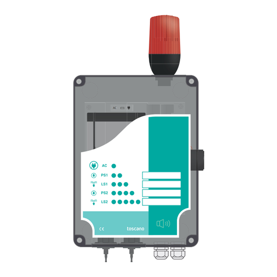
ALARM-BOX-ST
AC
AC
0.8 Ah
0.8 Ah
0.8 Ah
0.8 Ah
0.8 Ah
0.8 Ah
+
+
12V
12V
12V
12V
L
L
N PE
N N
N
PE
PS1
PS1
PS1 PS2
PS1
PS2
PS2
PS2
ENGLISH ( EN ) User manual
Acoustic & luminous alarm panel for loss of pressure
(pressure switches) or high/low level (fl oat switches
LS2
LS2
C OK AL
C OK AL
Ed. 1.21
Advertisement

Subscribe to Our Youtube Channel
Related Manuals for toscano tcontrol ALARM-BOX-ST


Summary of Contents for toscano tcontrol ALARM-BOX-ST
- Page 1 ALARM-BOX-ST Ed. 1.21 ENGLISH ( EN ) User manual Acoustic & luminous alarm panel for loss of pressure (pressure switches) or high/low level (fl oat switches 0.8 Ah 0.8 Ah 0.8 Ah 0.8 Ah 0.8 Ah 0.8 Ah N PE PS1 PS2 C OK AL C OK AL...
- Page 2 CONTENT ENGLISH (EN) 1. INTERNAL LAYOUT......................2 2. SETTING-UP (WALL MOUNTING) ..................3 3. POWER CONNECTION ......................4 4. LEVEL CONTROL INPUTS ....................5 5. PRESSURE CONTROL ......................6 6. ALARM OUTPUT (C - OK - AL) ....................7 7. OPERATION ..........................8 8. ADDITIONAL INFORMATION....................9...
- Page 3 There is a risk of electric shock if this warning is not heeded. WARNING: If the equipment is used or modified outside the manufacturer’s specifications, Toscano disclaims all liability due to improper use. The interior of the equipment should only be handled by personnel of our technical service.
- Page 4 1. INTERNAL LAYOUT Red Beacon AC supply LED. Sealed lead battery 12V 0.8 Ah Beacon connection 12VDC Buzzer connection 12VDC Optional AC pilot 12VDC 0.8 Ah Buzzer 90 db N PE PS1 PS2 PS1 PS2 Relay output (OK/ALARM) C OK AL Level sensor 2 (LS2) Level sensor 1 (LS1) Power supply input 230V...
- Page 5 2. SETTING-UP (WALL MOUNTING) Clamping brackets mounting Place the fixing brackets in the anchor points established for this purpose. Drill holes in the wall using the location where you have placed the fixing brackets. Insert the screws to anchor the equipment by using the fixing brackets.
- Page 6 3. POWER CONNECTION L L L L L L L L L L N N N N N N N N N N C OK AL 230 VAC The unit must be only connected to power mains equipped with a short circuit fuse protection.
- Page 7 4. LEVEL CONTROL INPUTS High level advice LS1 / LS2 ● Usual colours When the fl oat switch goes up, the electrical contact closes between BLACK (common) BROWN (n.c.). BLUE wire should be isolated. Low level advice LS1 / LS2 ●...
- Page 8 5. PRESSURE CONTROL Connect a fl exible rubber tube with an inner diameter of 3 to 4 mm (tube not included) to the nozzle of the pressure switches. The activation pressure can be adjusted on the pressure switch. ATTENTION: It is necessary to UNLOCK the adjusting wheel by raising the lock latch. After adjust, it is recommended to lock the latch again.
- Page 9 6. ALARM OUTPUT (C - OK - AL) The connection of this output is optional. Additional signalization elements can be operated with this relay. If everything is correct and supply power is present, the relay contacts are closed between Common (C) and OK. N PE C OK AL The contact will be closed between the Common (C) and Alarm (AL) points in case of:...
- Page 10 7. OPERATION Battery connection The panel is shipped with the battery connector unplugged. Do not forget to connect the battery for a proper operation. Alarm delay Any problem must be maintained for at least 15 seconds before alarm trip. Alarm will be cleared when the problem is solved.
- Page 11 8. ADDITIONAL INFORMATION Battery charge The panel keeps the battery always charged. If the battery if fully discharged, the panel may need several hours to charge it completely. Deep discharge protection The unit will protect the battery against a deep discharge that could damage it, disconnecting all alarms if the battery voltage is below 9 volts.
- Page 12 Toscano Línea Electrónica, S.L. Av. A-92, Km. 6,5 - 41500 - Alcalá de Guadaíra - SEVILLA - SPAIN (+34) 954 999 900 - www.toscano.es - info@toscano.es...
Need help?
Do you have a question about the tcontrol ALARM-BOX-ST and is the answer not in the manual?
Questions and answers