
Subscribe to Our Youtube Channel
Related Manuals for CMC AIRMASTER Q Series


Summary of Contents for CMC AIRMASTER Q Series
- Page 1 Q Series Configuration Manual Q Series Configuration Manual Positive Displacement Compression Compressor and Machine Controls...
-
Page 2: Table Of Contents
Monitorit and Networkit logos are trademarks or or website may provide or recommendations it may registered trademarks of CMC NV. All other make. Further, readers should be aware that trademarks are the property of their respective internet websites listed in this work may have trademark owners. - Page 3 CMC if Customer fails to comply with any provision of this License. CMC warrants that for a period of ninety (90) days from the date of shipment from CMC the Software Software, including technical data, is subject to substantially conforms to its published Belgium export control laws.
-
Page 4: Section 1: Safety
European Machine EMC Directive EMC 2.6 System Management Control 2014/30/EU and LVD 2014/35/EU. CMC System Management Control products The controller is a component that can not are used to fully integrate, optimise and operate without other components. The manage multiple equipment systems. -
Page 5: Section 3: User Interface
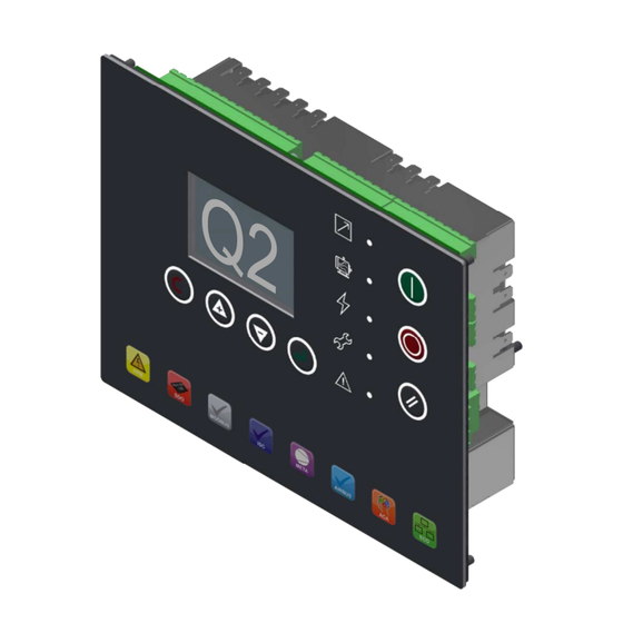
Q Series Configuration Manual Section 3: User Interface 3.1 Keypad 3.2 Graphic Display Start Stop Reset Enter Down After a period of non-use the graphic display light level will reduce until a key is pressed. Escape P00 is the default view page after power up and where the display will return after a period Icon: Image Icon: Function... - Page 6 Q Series Configuration Manual The ‘ADMIN’ user PIN Code can be changed Notes: Understand how to edit the ‘Default’ as required. The reset ‘ADMIN’ User PIN code User account which is done feature is intentionally not printed. If you do differently from the ‘ADMIN’...
-
Page 7: Menu Navigation
Q Series Configuration Manual 3.4 Menu Navigation Use the UP and DOWN keys to navigate between menu items. Menu content items are Menu tabs are arranged sequentially and in a vertically listed and in a continuous loop. continuous loop. The graphical interface inverts to identify the ‘on screen’... -
Page 8: Controls Studio
Q Series Configuration Manual 3.5 Controls Studio User Configurable Files: .cpb Controls Studio is a Windows™ PC Parameter settings. .cpba software application that allows Login user account profiles. configuration of an Airmaster™ Q .cpbu Series from a PC environment. OEM equipment data and Service Provider information .vis All user menu item visibility... -
Page 9: Menu Map
Q Series Configuration Manual – Positive Displacement Compression 4.0 Menus and Menu Items (BLACK Q1 and Q2) (BLUE: Q2 only 4.1 Menu Map (display menus may vary in relation to Airmaster™ configuration) Read and Edit Menu Read and Edit Menu Menu Colour Key: Read Only Menu (Keyboard or Controls Studio) - Page 10 Q Series Configuration Manual – Positive Displacement Compression 11 CLR SER NUM 11 USER 9 11 RS485 X06 CONFIG 11 CNDS Off Load 12 CLR YR MANUF 12 USER 10 Start Source 12 HI MTR STR HR 13 PV Inspect Date Load Source 13 DP Inhibit Time 14 Language...
- Page 11 Q Series Configuration Manual – Positive Displacement Compression 21 P00.03 CONFIG 21 N/A 21 Air Filter DP 21 EQUIP Out TEMP H 22 P00.04 CONFIG 22 N/A 22 Oil Filter DP 22 Cooling System 23 P00.05 CONFIG 23 N/A 23 SEP Filter DP HI 23 Main Motor Fault 24 Restart Reminder 24 N/A...
- Page 12 Q Series Configuration Manual – Positive Displacement Compression DI5 Config DI5 Function Q1: 09 Analog Input 5 Analogue Input 1 Digital Input 9 option DI6 Function DI5 Config Analog Input 4 Analogue Input 2 Digital Input 10 DI6 Config DI6 Function Analog Input 5 11-13 Analogue Input 3...
- Page 13 Q Series Configuration Manual – Positive Displacement Compression ANA IN 9 Type L3 Frequency ANA IN 10 Funct L1 Phase Angle ANA IN 10 Type L2 Phase Angle Relay 1 Function L3 Phase Angle Relay 2 Function Key Switch Test Relay 3 Function LED Test Relay 4 Function...
-
Page 14: Menu Items
Q Series Configuration Manual – Positive Displacement Compression 4.2 Menu Items (BLACK Q1 and Q2) (BLUE: Q2 only Menu name Menu code Menu text Additional information Home Page (display will default to the Home Page if no keypad activity occurs for a period of time) The most recent active alarm. - Page 15 Q Series Configuration Manual – Positive Displacement Compression P01.07 Service Hours 2 Hour counter, visible when configured and displays assignment (e.g. cabinet filter) Service P01.08 Service Hours 3 Hour counter, visible when configured and displays assignment (e.g. air filter) Timers P01.09 Service Hours 4 Hour counter, visible when configured and displays assignment (e.g.
- Page 16 Q Series Configuration Manual – Positive Displacement Compression P03.##.05 EQUIP Status Where ## = 01 to 50, Equipment status when error occurred P03.##.06 EQUIP OUT PRESS Where ## = 01 to 50, Equipment outlet pressure when error occurred Error Log P03.##.07 EQUIP INT PRESS Where ## = 01 to 50, Equipment internal pressure when error occurred...
- Page 17 Q Series Configuration Manual – Positive Displacement Compression P07.02 EQUIP Model Equipment (Package) model P07.03 MDL SER Number Model serial number P07.04 MDL Rated PRESS Model rated pressure P07.05 MDL Rated Output Model rated output P07.06 MDL YR MANUF Model year of manufacture Service P07.07 COMP SER NUM...
- Page 18 Q Series Configuration Manual – Positive Displacement Compression P08.23 A:0901 CONF alarm 1. Configurable alarm 1. Digital input not OK P08.24 A:0902 CONF alarm 2. Configurable alarm 2. Digital input not OK P08.25 A:0903 CONF alarm 3. Configurable alarm 3. Digital input not OK P08.26 A:1001 COMP OUT T°...
- Page 19 Q Series Configuration Manual – Positive Displacement Compression P08.64 A:4811 Belt drive SERV. Service due P08.65 A:4812 ELEC SYS SERV. Service due P08.66 A:4813 MTR bearing SERV. Service due P08.67 A:4814 COMP BRG SERV. Service due P08.68 A:4815 Dryer service. Service due P08.69 A:4816 Oil service.
- Page 20 Q Series Configuration Manual – Positive Displacement Compression P08.105 E:0082 Main motor OVLD. Main motor overload. Consult manual (CT input function) P08.106 E:0083 Motor phase IMB. Main motor phase imbalance. Consult manual P08.107 E:0084 Main MTR CT SENS. Main motor current sensor. Consult manual P08.108 E:0085 Fan MTR CT sensor.
- Page 21 Q Series Configuration Manual – Positive Displacement Compression P08.146 E:0901 CONF ALARM 1. User configurable immediate stop 1 P08.147 E:0902 CONF ALARM 2. User configurable immediate stop 2 P08.148 E:0903 CONF ALARM 3. User configurable immediate stop 3 P08.149 E:0971 Cooling SYS FLT.
- Page 22 Q Series Configuration Manual – Positive Displacement Compression P08.187 E:4815 Dryer service. Service due P08.188 E:4816 Oil service. Service due Message P08.189 E:4817 Cooler service. Service due Codes P08.190 E:4818 Oil/Fog SEP SERV. Service due P08.191 E:4819 Routine service. Service due P08.192 E:4820 Weekly service.
- Page 23 Q Series Configuration Manual – Positive Displacement Compression P09.02.08 Initial User Select Initial User at startup from the list of users Access P09.03 User 1 Enter User 1 account settings P09.03.01 Edit User Name Eight alphanumeric characters P09.03.02 User PIN Code Four digit numeric number P09.03.03 Language...
- Page 24 Q Series Configuration Manual – Positive Displacement Compression P09.10 User 8 User 8 sub menu (sub-menu items as described for User 1) P09.11 User 9 User 9 sub menu (sub-menu items as described for User 1) P09.12 User 10 User 10 sub menu (sub-menu items as described for User 1) Equipment Settings Equipment settings are grouped in a number of ‘Equipment Settings’...
- Page 25 Q Series Configuration Manual – Positive Displacement Compression 300, 600, 1200, 1800, 2400, 4800, 9600, 14400, 19200, 28800, 38400, 57600, 115200, 230400, 460800 or P10.09.04 MODBUS Baud Rate 931600 P10.09.05 MODBUS Parity ‘no parity’, ‘odd parity’, ‘even parity’, ‘zero parity’ or ‘one parity’ P10.09.06 MODBUS Data Bits 5 to 8...
- Page 26 Q Series Configuration Manual – Positive Displacement Compression P10.14 Language Menu list selection P10.15 Time Internal ‘Real Time Clock’ Time P10.16 Time Format 24:00 (24 hour) or 12:00 a/p (12 hour AM / PM) Equipment P10.17 Daylight Saving ‘+0h’ or ‘+1h’ Settings 1 P10.18 Date...
- Page 27 Q Series Configuration Manual – Positive Displacement Compression Minimum main motor run time once started. The Off Load Run Time will be dynamically extended if the minimum main motor run time has not been P11.02 MIN MTR Run exceeded during the current running cycle of operation. OFF or 1 to 1800 seconds.
- Page 28 Q Series Configuration Manual – Positive Displacement Compression The time the ‘Drain’ output will energise each cycle when the equipment is loaded. CNDS Drain INT - Condensate Drain Interval Time: 60 to 3600 seconds P11.10 CNDS Drain INT The time the ‘Drain’ output will remain de-energised each cycle when the equipment is loaded. When not loaded the interval time is extended by a factor of 10 (CNDS Drain INT x 10).
- Page 29 Q Series Configuration Manual – Positive Displacement Compression Annual: if the time since the last service due event will exceed one calendar year the service hours is automatically reduced so that the service due will occur at one calendar year since the last service due event. Bi-Annual: if the time since the last service due event will exceed six calendar months the service hours is automatically reduced so that the service due will occur at six calendar months since the last service due event.
- Page 30 Q Series Configuration Manual – Positive Displacement Compression as ‘Service Hours 1’ P11.21.0 Function Equipment Note: set the Service Hours time in menu P16.08 Settings 2 P11.21.02 Pre Condition as ‘Service Hours 1’ P11.21.03 IMM Stop Enable P11.21.04 Time Limit ON or OFF P11.22 Weekly Service...
- Page 31 Q Series Configuration Manual – Positive Displacement Compression P12.06 Error Log Reset YES: delete the Error Log file, clear the error log P12.07 Event log reset YES: delete the Event Log file, clear the event log The start date for all total hour’s logs. P12.08 Total HRS STR Set to the commissioning date to synchronise total hours logs with commissioning of equipment...
- Page 32 Q Series Configuration Manual – Positive Displacement Compression P12.26 No function in standard software Continuous Dryer: runs continuously when the equipment is running P12.27 Dryer Type Refrigerant Dryer: uses the dryer on/off settings in P12.28 & P12.29 Equipment Dryer Off Temperature Dryer off temperature set point P12.28 Settings 3...
- Page 33 Q Series Configuration Manual – Positive Displacement Compression Variable Speed/Frequency Drive (VSD) Settings VSD control modes selection. Press ‘ENTER’. Use the ‘UP’ and ‘DOWN’ keys to configure between ‘ P13.01 VSD Control Mode VAR Speed CTRL: variable speed control when loaded, OFFLOAD SPEED when off load. Fixed Speed Control: OPTIMUM SPEED when loaded, OFFLOAD SPEED when off load.
- Page 34 Q Series Configuration Manual – Positive Displacement Compression Note: When skip frequency 1 low set point is adjusted to a value greater than OFF, skip frequency 1 high menu and skip frequency 2 low menu are revealed. Similarly, when skip frequency 2 low set point is adjusted to a value greater than OFF, skip frequency 2 high menu and skip frequency 3 low menu are revealed.
- Page 35 Current Transformer (CT) Selection: A comprehensive range of CT’s, from 5 to 650 Amps, are available from CMC. Select a CT where the ‘Motor Nominal Current’ exceeds 40% of the CT maximum rating but no greater than 80% of the maximum CT rating.
- Page 36 Q Series Configuration Manual – Positive Displacement Compression The nominal ‘Lock Rotor Current’ for a typical industrial 3-phase induction motor = 6 x ‘Nominal Motor Current’ example – Main Motor: 37kW, 66A Nominal Motor Current 66A x 6 =396 Amps example –...
- Page 37 Q Series Configuration Manual – Positive Displacement Compression Under Current Detection: The Airmaster™ monitors the presence of current in any running state. If the detected current is less than 20% of the ‘Nominal Motor Current’ the Airmaster™ will assume this to be an abnormal under current condition and an immediate stop event will occur. Main Motor Phase Imbalance Protection: Main motor phase imbalance protection measures any deviation in the phase currents.
- Page 38 Q Series Configuration Manual – Positive Displacement Compression Airmaster™ WARNING ALARM Conditions. Warning Alarm: will generate and log an Alarm indication but will not stop the equipment from operating. P16.01 Service Hours 1 P16.02 Service Hours 2 P16.03 Service Hours 3 0 to 10,000 hours P16.04 Service Hours 4...
- Page 39 Q Series Configuration Manual – Positive Displacement Compression Note1: Differential Pressure Warning is disabled when delivery temperature is below 50°C Note2: Differential Pressure must continuously exceed the limit for more than 10 seconds Oil / Air Separator Differential Pressure High Warning: Oil Air SEP DP HI minus EQUIP OUT PRESS OFF or 0.01 Bar to 2.00 Bar P16.16 Oil Air SEP DP HI...
- Page 40 Q Series Configuration Manual – Positive Displacement Compression Note: requires appropriate digital input assignment. See Menu P18 Filter Drain Warning Alarm P16.30 FTR Drain ALM ON or OFF Note: requires appropriate digital input assignment. See Menu P18 Oil/Water Separator Warning Alarm P16.31 Oil/WTR SEP ALM ON or OFF...
- Page 41 Q Series Configuration Manual – Positive Displacement Compression Q2: P16.57 FLAT Motor PROT Main motor, greater than: OFF or 0.22A to 249.99A Q2: P16.58 FLAT Motor PROT Fan motor, less than: OFF or 0.03A to 4.98A Warning Alarms Q2: P16.59 FLAT Motor PROT Fan motor, greater than: OFF or 0.04A to 4.99A Airmaster™...
- Page 42 Q Series Configuration Manual – Positive Displacement Compression OFF: disabled ON: motor overload determined by P14 menu values OR fan motor overload digital input Phase Detection Immediate Stop P17.11 Phase Detection OFF: disabled ON: phase order (L1>L2>L3) is incorrect OR loss of phase ON or OFF P17.12 Door Open...
- Page 43 Q Series Configuration Manual – Positive Displacement Compression Note: requires appropriate digital input assignment, see Menu P18 Configurable Immediate Stop #2 P17.25 Conf IMM stop 2 ON or OFF Note: requires appropriate digital input assignment, see Menu P18 Configurable Immediate Stop #3 P17.26 Conf IMM stop 3 ON or OFF...
- Page 44 Q Series Configuration Manual – Positive Displacement Compression P18.01 - AO 1 Function Analogue Output 1 Function sub-menu P18.02 - AO 2 Function Analogue Output 2 Function sub-menu Disable, No function Q2: Blower Speed Repeat: blower speed, 4-20mA Q2: Inlet Pressure Repeat: inlet pressure, 4-20mA Alarm Energise: Warning Alarm (not including Start/Run Inhibit OR Immediate Stop)
- Page 45 Q Series Configuration Manual – Positive Displacement Compression Disable, No function Select Enclosure T HL Select Vibration HL Select Doors Open alarm Select Doors Open Trip Select CAB Filter DP Select Air Filter DP Select Oil Filter DP Select SEP Filter DP HI Select Fan Motor Alarm Select...
- Page 46 Q Series Configuration Manual – Positive Displacement Compression Select User Trip 1 Select User Trip 2 Select User Trip 3 Select Water Flow Select Inverter Fault Select Ambient TEMP HI Select Main MTR TEMP HI Select EQUIP out TEMP HI Motor Protection - Select Main Motor Fault Select...
- Page 47 Q Series Configuration Manual – Positive Displacement Compression Select Group Fault P18. Select Dew Point 02(03)~15(32) Select Q1(Q2) Dew Point Select EQUIP OUT PRESS Select Dryer Power SUP Select Dryer Power SUP Force Spiral VLV Select Configure input for ‘Normally OPEN’ or ‘Normally CLOSED’ P18.0#.01 Open / Closed Note: if set for (Open) feature will activate when input is CLOSED circuit, if set for (Closed) feature will...
- Page 48 Q Series Configuration Manual – Positive Displacement Compression Energise: detected Temperature falls below set low temperature run inhibit + 2°C. Heater NO De-energise: detected temperature increases above set low temp run inhibit + 3°C Drain NC De-energise: when Drain function in active ‘ON’ state. Drain NO Energise: when Drain function in active ‘ON’...
- Page 49 Q Series Configuration Manual – Positive Displacement Compression Auto Restart NC De-energise: when ‘Auto Restart’ is enabled P18. Auto Restart NO Energise: when ‘Auto Restart’ is enabled. 16(53)~19(66) Star Delta TRANS NC De-energise: during the main motor starter ‘Star Time’ (P11.01) Q1(Q2) Star Delta TRANS NO Energise: during the main motor starter ‘Star Time’...
- Page 50 Q Series Configuration Manual – Positive Displacement Compression Force Spiral VLV NC De-energise: when digital input assigned to ‘Force Spiral VLV ‘ is NOT OK Force Spiral VLV NO Energise: when digital input assigned to ‘Force Spiral VLV ‘ is NOT OK P18.20(33) ANA IN 1 FUNCT Q1: No edit, fixed: EQUIP OUT PRESS (4-20mA),...
- Page 51 Q Series Configuration Manual – Positive Displacement Compression P19.02 EQUIP INT PRESS EQUIP INT PRESS sub menu. Sensor Offset Calibration. To calibrate ‘Offset’: expose the sensor to atmosphere and adjust the offset value until P19.02.03 displays P19.02.01 Value Offset 0.0bar. For example, the sensor has a –1.0 (minus one) to 15.0bar range;...
- Page 52 Q Series Configuration Manual – Positive Displacement Compression P19.07.05 MEASURE Offset Analogue Input 2 Offset Calibration P19.07.06 MEASURE Range Analogue Input 2 Range Calibration P19.07.07 Analog Input 2 Analogue Input 2 Value – no edit, view only Sensor P19.08 Analog input 3 Analogue Input 3 sub menu CONFIG P19.08.01...
- Page 53 Q Series Configuration Manual – Positive Displacement Compression Airmaster™ Diagnostics P20.01 Digital Input 1 P20.02 Digital Input 2 P20.03 Digital Input 3 P20.04 Digital Input 4 P20.05 Digital Input 5 P20.06 Digital Input 6 P20.07 Digital Input 7 P20.08 Digital Input 8 View Digital Input State: OPEN / CLOSED Q2: P20.09 Digital Input 9...
- Page 54 Q Series Configuration Manual – Positive Displacement Compression Analogue Input 9 Press ‘Enter’ to view ‘Assignment’ and ‘Value’ (current) Analogue Input 9 ‘resistance (Ohms)’, ‘current (mA)’ or ‘voltage (0-10V)*’ dependant on analogue input configuration (voltage Analog. Input 10 Q2: Analogue Input Raw Value (LED Card #2 Option) (resistive) Q2: P20.26 Analog.
- Page 55 Q Series Configuration Manual – Positive Displacement Compression Airmaster™ Run Schedule Real Time Clock Schedule Automation Functions P21.01 Run Schedule ON or OFF Press ‘ENTER’ to access sub menu P21.02.## P21.02 Workday Edit Set each day, Monday to Sunday, individually as appropriate for region P21.02.01 Monday Workday or Weekend...
- Page 56 Q Series Configuration Manual – Positive Displacement Compression Time P21.04.08 Time Only visible if Frequency = ‘Configured Date’ Press ‘ENTER’ to store the configured values in P21.04.01 to P21.04.08 to permanent memory. P21.04.09 Save Changes Run Schedule Note: To save changes, this action must be taken before exiting the sub-menu P21.05 P21.05 Schedule Entry 2 to 28 Sub Menus...
- Page 57 Q Series Configuration Manual – Positive Displacement Compression Total Number of Compressors in the ISC System P81.01 ISC # Compressors 2 to 8 (Default = 4) Staggered Start Delay Time P81.02 ISC Start Delay 0 to 60 seconds (Default = 3 seconds Delay between starting compressors where more than one compressor needs to be started at the same time.
- Page 58 Q Series Configuration Manual – Positive Displacement Compression P82.01 COMP1 Priority Compressor 1 Priority ISC (Integrated P82.02 COMP2 Priority Compressor 2 Priority System P82.03 COMP3 Priority Compressor 3 Priority Control) P82.04 COMP4 Priority Compressor 4 Priority P82.05 COMP5 Priority Compressor 5 Priority P82.06 COMP6 Priority Compressor 6 Priority...
-
Page 59: General Operation
Q Series Configuration Manual – Positive Displacement Compression 5.0 General Operation The equipment outlet pressure regulates control once the ‘START’ button has been pressed. The Airmaster™ will perform condition checks and start if no ‘Start’ inhibit exists. If a ‘Start’ inhibit exists, a start will be prevented and an inhibit message will be displayed. - Page 60 Q Series Configuration Manual – Positive Displacement Compression 5.1 Airmaster™ State Diagram STOPPED 1: Fault Condition 2: Power-Up Initialisation 3: Start Inhibit 4: Ready to Start STARTED 5: Run Inhibit / Vent Time 6: STANDBY RUNNING 7: Motor Start 8: Load Inhibit RUNNING LOADED 9: ON LOAD RUNNING...
-
Page 61: Control Modes
Q Series Configuration Manual – Positive Displacement Compression 5.2 Control Modes Load / Off Load: Airmaster™ loads and unloads in accordance with the set load and unload pressure set points. If running off load for longer than the “Off Load Run Time” the Airmaster™ will stop in the ‘Standby’ state. When in ‘Standby’... - Page 62 Q Series Configuration Manual – Positive Displacement Compression Dynamic No Load Control As ‘Load / Off Load’ description except the ‘Off Load Run Time’ is dynamically determined in accordance with the number of permissible ‘Starts Per Hour’ (configurable). The ‘Run-On Time’ period is dynamically determined to ensure the set permissible main motor ‘Starts Per Hour’ limit can not be exceeded during any given hour period.
-
Page 63: Text Abbreviations
Q Series Configuration Manual – Positive Displacement Compression 6.0 Text Abbreviations: Abbreviation Text Abbreviation Text ACTIVE Active or Activated MANUF Manufacture ADCT Air end (compressor) discharge temperature March Automatic drain valve Maximum Analogue input Model Alarm or alarm message META Metacentre Ambient Minimum... - Page 64 Q Series Configuration Manual – Positive Displacement Compression Default Pressure relief valve Digital input PSENS Pressure sensor DISCH Discharge PSWITCH Pressure switch DIFF Differential Pressure vessel Differential pressure Refrigerant Differential temperature Range Direction Random access memory Digital output Remote bus Direct online Remote contact DIR ROTO...
-
Page 65: Language Codes
Q Series Configuration Manual – Positive Displacement Compression JUNE June Unit of measurement Kelvin Variable speed drive LOCAL Local Year Lubrication 7.0 Language Codes Code Language English (English) Беларуская (Belarusian) Czech (Czech) Deutsch (German) Espanol (Spanish) Français (French) Ελληνικά (Greek) Italiano (Italian) 日本... -
Page 66: Logged Events
Q Series Configuration Manual – Positive Displacement Compression 8.0 Logged Events Each logged event (P04.01.01 – P04.01.200) includes an event index, event description and an event time and date. Logged Events START button pressed STOP button pressed PARA reset to DEF (Parameter reset to default) Active ‘USER #’... -
Page 67: Use Of Menu Pages And Page Items 12.0 Symbols
Q Series Configuration Manual – Positive Displacement Compression 11.0 Use of Menu Pages and Page Items Airmaster™ menu page items are arranged sequentially from P00 to P99, menu items 01 to 99. Some menu pages or menu page items are intentionally omitted or not displayed dependant on software variant and/or configuration/setup. Default menu page (P##) numbers and titles: Page Display name... - Page 68 Q Series Configuration Manual – Positive Displacement Compression Motor Range or Detected Total Hours Set Point Set Point, Upper Limit Set Point, Lower Limit Read Only Unlocked or Accessible Locked or Not Accessible Date Start Delta Delta pressure Auto Restart Filter Down Audible Alarm...
-
Page 69: Help And Support
Contact your original equipment manufacturer or your original equipment manufacturer’s nominated representative. Compressor & Machine Controls NV (CMC NV) is a provider of Airmaster™ product solutions to original equipment manufacturers (OEM’s) only. CMC NV is not able to support end users or nominated representatives of OEM equipment in the use, operation or fault diagnostics of Airmaster™ products.
Need help?
Do you have a question about the AIRMASTER Q Series and is the answer not in the manual?
Questions and answers