Table of Contents
Advertisement
CMC NV – Airmaster Q1 Installation Guide – V1.0 – MANY1032A.EN.00
MANY1032A.EN.00
Airmaster Q1 hardware Installation Guide
Version 1.0
SAFETY WARNING
Do not operate the Airmaster Q1 until you and all personnel concerned have read
and understood this installation guide. Failure to follow instructions could result
in death or serious injury.
Important notes
This document serves as installation guide for all Airmaster Q1 products of CMC NV.
Installation and startup may only be done by trained personnel according to safe
engineering practices and with the observance of all relevant local health and safety
requirements and regulations.
A requirement of fault-free operation and fulfillment of any rights to claim under
guarantee is that the documentation is observed. In case of doubt please contact CMC.
This document could be subject to changes. Please contact our factory in case of doubt
in order to ensure that you have received the latest version.
The Airmaster Q1 is further referred to as the "controller".
This document serves as a manual for the installation of the controller. Remark that the
controller always acts as a component of a complete system in which it is integrated. As
such other documentation for the installation related to the integration of the controller in
the complete system will have to be consulted as well. Reference to such other
documentation is not possible from within the scope of this document. Regardless of the
content of any other documentation, the content of this documentation needs to be fully
respected.
CMC NV, Industriezone Klein Frankrijk, Klein Frankrijkstraat 40, 9600 Ronse, Belgium
Advertisement
Table of Contents

Related Manuals for CMC Airmaster Q1


Summary of Contents for CMC Airmaster Q1
- Page 1 Airmaster Q1 hardware Installation Guide Version 1.0 SAFETY WARNING Do not operate the Airmaster Q1 until you and all personnel concerned have read and understood this installation guide. Failure to follow instructions could result in death or serious injury. Important notes This document serves as installation guide for all Airmaster Q1 products of CMC NV.
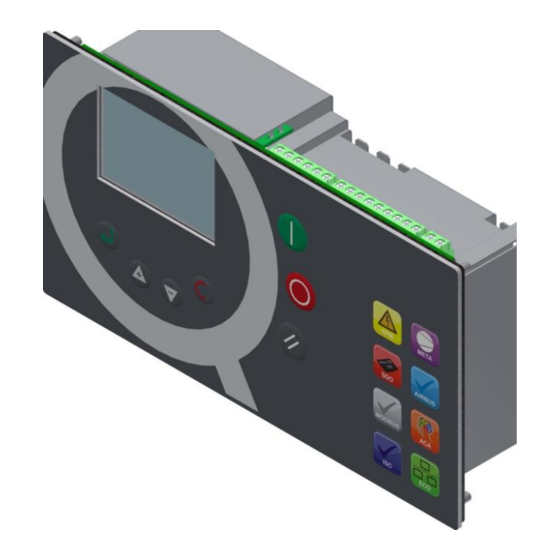
- Page 2 CMC NV – Airmaster Q1 Installation Guide – V1.0 – MANY1032A.EN.00 Illustration of Airmaster Q1. Remark the layout of the front panel can be different from the above picture. Page 1...
- Page 3 CMC NV – Airmaster Q1 Installation Guide – V1.0 – MANY1032A.EN Limit of Liability The publisher and the author make no representation or Trademarks warranties with respect to the accuracy or completeness of the contents of this work and specifically disclaim all warranties, including without limitation warranties of fitness for a particular purpose.
-
Page 4: Table Of Contents
CMC NV – Airmaster Q1 Installation Guide – V1.0 – MANY1032A.EN Installation guide Table of Contents Section 1: Situation of the product ............................4 Section 2: Safety ..................................5 Section 2.1: Safety warning ..............................5 Section 2.3: Operation ................................. 6 Section 2.4: Maintenance .............................. -
Page 5: Section 1: Situation Of The Product
CMC NV – Airmaster Q1 Installation Guide – V1.0 – MANY1032A.EN Section 1: Situation of the product The controller is an industrial controller. This hardware installation guide is a guide for the hardware related items. Refer to the software specifications file for information on how to work with the unit. -
Page 6: Section 2: Safety
CMC NV – Airmaster Q1 Installation Guide – V1.0 – MANY1032A.EN of power to the controller when required to do so. Use Section 2: Safety extreme caution when carrying out electrical checks. Section 2.1: Safety warning Never remove or tamper with safety devices, guards or... -
Page 7: Section 2.3: Operation
CMC NV – Airmaster Q1 Installation Guide – V1.0 – MANY1032A.EN visibility of indicators at all times. relevant and local safe isolation procedures. As this product is installed on and integrated with other After any intervention, the controller shall be completely... -
Page 8: Section 3: Ratings
CMC NV – Airmaster Q1 Installation Guide – V1.0 – MANY1032A.EN Section 3: Ratings Max operating ratings: Temperature: Power supply: CAT II 24V ac/dc 0 °C – 55 °C Operating: -25 °C – 75 °C Relays: Storage: Overvoltage X09, X08, X07 Humidity: <... -
Page 9: Section 4: Connections And Protection
CMC NV – Airmaster Q1 Installation Guide – V1.0 – MANY1032A.EN Section 4: Connections and Protection Remarks: It remains the responsibility of the integrator of this controller (being a component in the total system) to assure that the integration of the controller (in terms of wiring and use of other components) is done according to all applicable regulations. -
Page 10: Section 4.2. Power
CMC NV – Airmaster Q1 Installation Guide – V1.0 – MANY1032A.EN Section 4.2. Power Indication: 24Vac 24Vac shall be supplied by transformer in which the primary windings are separated from the secondary windings by reinforced insulation, double insulation or a screen connected to the positive conductor terminal. Do not connect any of the leads of the secondary winding to earth as this can result in severe damage of the controller. -
Page 11: Section 4.4 Relays
CMC NV – Airmaster Q1 Installation Guide – V1.0 – MANY1032A.EN The digital inputs are addressed via external contacts between C-I and the DI1 .. DI8 connections. Connector reference: X02 Section 4.4 Relays R1 .. R8 shall be protected against over-current. Absolute maximum current is 8A (resistive). - Page 12 CMC NV – Airmaster Q1 Installation Guide – V1.0 – MANY1032A.EN Three fixed analog inputs are available. All three have 2 dedicated connections: Analog input 1: Connections C-ANA1 and AN1 current input: 4 .. 20 mA Analog input 2: Connections C-ANA2 and AN2 current input: 4 ..
-
Page 13: Section 4.6 Analog Output
CMC NV – Airmaster Q1 Installation Guide – V1.0 – MANY1032A.EN In X15 or X16 it is possible that one optional analog input is available. Such input can be recognized by having 3 connection pins in its connector. If a connector with 2 connection pins is installed, it is a RS485 connector (see further). -
Page 14: Section 4.7 Communication
CMC NV – Airmaster Q1 Installation Guide – V1.0 – MANY1032A.EN Functional earthing In case the external components demand for a GND connection (such as for functional earthing, It is recommended to use shielded cabling for analog signals), it is advised to use the faston connection: Connector reference: X01 Section 4.7 Communication... -
Page 15: Section 4.8 1-Phase Current Sensor
CMC NV – Airmaster Q1 Installation Guide – V1.0 – MANY1032A.EN Such input can be recognized by having 2 connection pins in its connector. If a connector with 3 connection pins is installed, it is an analog input connector (see above). -
Page 16: Section 4.9 3-Phase Current Sensor
CMC NV – Airmaster Q1 Installation Guide – V1.0 – MANY1032A.EN This input is only to be connected to a Current Transformer (CT) supplied by CMC. The selection of CT is done in accordance with the installation and is as such not covered by this manual. Assure the maximum C.T. rating is 20 mA. Do not connect a C.T. -
Page 17: Section 4.10 3-Phase Monitoring Inputs
CMC NV – Airmaster Q1 Installation Guide – V1.0 – MANY1032A.EN Section 4.10 3-Phase monitoring inputs In operation, high lethal voltages apply on these connections. Assure all power is switched off at the moment of installation. Never assume power is off but always check the circuit. -
Page 18: Section 5: Mounting
CMC NV – Airmaster Q1 Installation Guide – V1.0 – MANY1032A.EN Section 5: Mounting The Airmaster Q1 must be mounted in a front panel, enclosure or housing, which must have a suitable protection degree for the electronics. Components required (not delivered with the controller) ... - Page 19 CMC NV – Airmaster Q1 Installation Guide – V1.0 – MANY1032A.EN Mounting of the controller (do respect the recommended torque setting): Illustration of a well mounted controller: Page 18...
Need help?
Do you have a question about the Airmaster Q1 and is the answer not in the manual?
Questions and answers
where we can buy 1 unit of this product; 1. SPARE PART, COMPRESSOR: PART NAME: CONTROLLER; PART NUMBER: STTY10024; TYPE AND SIZE: Q1; BRAND PROVEN: AIR MASTER;