Advertisement
Quick Links
This document describes the installation (page 2 - 4), configuration (page 5 - 7) and usage (page 8 - 9) of the Goblin-SPST MIDI mod
version 2.0.1. For a description of the product, its features and further information visit
Electrical Properties
Supply Voltage (+9V Terminal)
Current Consumption
Maximum voltage at RLY, LED and SW terminals
Output voltage at SW terminals
The Goblin-SPST has reverse polarity protection at the V+ terminal.
Be careful nonetheless to not reverse polarity upon installation, as
long as other wires are connected. Negative currents could flow
through the microcontroller and damage it.
Caution: Please read this manual carefully before making any connections. Be careful to not exceed any voltage limits.
Attention: Digital signals, such as MIDI signals, can lead to crosstalk on other lines. This particularly applies to effects with multiple
gain stages (distortion, fuzz, etc.). Pay attention to keep the MIDI wires as far away from the analog circuit as possible. Otherwise it
can happen that a click can be heard in the audio signal with every MIDI command. To further reduce possible crosstalk, use shielded
wires for audio and MIDI.
The main function of the Goblin-SPST-2.0 is to take control over effects devices that are controlled with non latching SPST (or (ON)-
OFF) footswitches. Additionally the 2.0 version is able to control connections for external footswitches, expression controls and – in
special cases – potentiometers. All these things can then be controlled with MIDI.
The Goblin-SPST has five ports, with 3 connections each, to control five functions of the effects device. Here's a quick overview over
the connections:
•
V+/GND: This is the power supply. Connect them
directly to the DC jack of the guitar pedal.
•
MIDI Sig: This is the active MIDI signal. It is
connected to Pin 5 of a DIN 5-PIN MIDI
Connector, or Tip if a TRS connector according to
MIDI standard (Type A) is used.
•
MIDI Ref: This is the reference MIDI signal. It is
connected to Pin 4 of a DIN 5-PIN MIDI
Connector, or Ring if a TRS connector according
to MIDI standard (Type A) is used.
•
MIDI GND: This is the GND signal for MIDI Thru. It is connected to Pin 2 of a DIN 5-PIN MIDI Connector, or Sleeve if a TRS
connector according to MIDI standard (Type A) is used. Note that only MIDI Outputs have a connection to GND. Do not connect
GND to the MIDI Input.
The connections of the ports have different functions depending on the Role of the port. The first port has always the role Switch
and is meant to be used for the bypass footswitch and to set the MIDI channel.
Default Role
Port 1
Switch
Port 2
Disabled
Port 3
Disabled
Port 4
Disabled
Port 5
Disabled
Goblin-SPST - Version 2.0.1
Min
Typ
Max
7
9
20
VDC
3
10
30
mA
5
VDC
5
VDC
MIDI In Ref
Pin 4/Ring
MIDI In Sig
Pin 5/Tip
GND
V+
Switch/Tap Tempo
Yes
Yes
Yes
Yes
Yes
https://oscillatordevices.com/ goblin
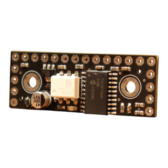
Height is approx. 8mm. If using the Goblin Screw set,
account at least for 15mm height.
PORT 1
PORT 3
PORT 2
External Footswitch
Expression/Potentiometer/CV
No
Yes
Yes
Yes
Yes
1
33mm
49mm
PORT 4
PORT 5
SW5/VREF
MIDI Thru Sig
Pin 5/Tip
MIDI Thru GND
Pin 2/Sleeve
MIDI Thru Ref
Pin 4/Ring
No
Yes
Yes
Yes
Yes
11 December 2024
Advertisement

Related Manuals for OSCILLATOR DEVICES Goblin-SPST-2.0


Summary of Contents for OSCILLATOR DEVICES Goblin-SPST-2.0
- Page 1 MIDI. The main function of the Goblin-SPST-2.0 is to take control over effects devices that are controlled with non latching SPST (or (ON)- OFF) footswitches. Additionally the 2.0 version is able to control connections for external footswitches, expression controls and – in special cases –...
- Page 2 MIDI Thru Sig MIDI In Sig Pin 5/Tip Pin 5/Tip MIDI Thru GND Pin 2/Sleeve MIDI Thru Ref Pin 4/Ring Dual Footswitch Effects Devices with Goblin-SPST-2.0 installed, using Port 1 and Port 4 Goblin-SPST - Version 2.0.1 11 December 2024...
- Page 3 The connection SW is for connecting a non latching SPST switch. All SW terminals have internal 5V pull ups. The other side of the switch has to be connected to GND, so the switch connects SW to GND, when closed. For regular cases, like the one above, the active (or high) side of the switch has to be disconnected from the effects device and connected to the Goblin, while the GND side stays connected.
- Page 4 Besides foot switches, the Goblin-SPST-2.0 can control external foot switch connections, like connections for external tap tempo switches, Strymon FAV-Switches etc. In the image below is a typical effects pedal with a bypass foot switch (left) and a TRS socket for an external foot switch (right).
- Page 5 Following is explained how to wire the Goblin-SPST for a single expression input without further explaining how it works. For that refer to the next chapter which is very long and technically. So, for a single expression input and only if you don’t use any other ports with the role Pot/CV, use port 5 for expression.
- Page 6 I wish this was easy. But it isn’t. To understand how the Pot/CV function works, we have to go through some basics. First, let’s have a look how the role Pot/CV works theoretically. The role Pot/CV generates a voltage dependent on either a voltage input, or a MIDI command.
- Page 7 In order to be able to adapt the Goblin to as many effects devices as possible, various parameters can be set via the configuration procedure. The configuration is always carried out via MIDI CC messages and consist of 4 messages per parameter. The actual configuration message, two passcode messages and a save message.
- Page 8 Some effects devices need some time to power up. This ranges from a few milliseconds to several seconds. So the Goblin can correctly restore the last state and the boot process of the effects device is not disturbed, a delay at the beginning can be useful. Function Startup delay n*100 ms (Default n = 5) Please note that a pressed button is immediately processed as soon as the Goblin is connected to the supply voltage, regardless of...
- Page 9 In order to save the above configurations, the following three commands must be called immediately one after the other. If another command is sent in between, the saving sequence is aborted. The effects device must be restarted for the changes to take effect. Function 1.
- Page 10 To put the Goblin in omni mode skip step 3. The Goblin-SPST-2.0 is able to save up to 20 presets. Saving a preset always saves the current state. That includes Pot/CV value either set by the Pot or MIDI command, state of the switches and state of the TRS ports. To save a preset, set the Goblin-SPST into preset save mode first.
- Page 11 If the port is in the role of an external switch (TRS, EXT, CTL etc.), this port then has two lines, referred to as "Tip" and "Ring", which emulates a plugged in external switch. This switch can be Normally Open (NO) or Normally Closed (NC), which is set during configuration (see chapter Roles).
- Page 12 The voltage of the port can set with this command. Function Port2: 30 Voltage from 0v to VREF in 127 steps. Port3: 50 0 = 0V, 127 = VREF with non inverted pot direction Port4: 70 127 = 0V, 0 = VREF with inverted pot direction Port5: 90 In addition, the Goblin-SPST starting with version 2.0.1 has an internal, MIDI clock synchronous, LFO engine with 3 waveforms to drive the Pot/CV.
-
Page 13: Lfo-Parameter
LFO-Parameter The waveforms set this way always run through the entire range, from heel to toe. The range can be reduced and moved. The waveforms are shifted in 13 steps, with step 6 being the waveform in the middle. This corresponds to the Offset in the graphic. Funktion Offset 0.
Need help?
Do you have a question about the Goblin-SPST-2.0 and is the answer not in the manual?
Questions and answers