Vaillant vSMART 0020197226 Manual
- Installation and maintenance instructions manual (20 pages) ,
- Operating instructions manual (16 pages) ,
- User manual (12 pages)
Advertisement
- 1 Safety
- 2 Minimum cross-section
- 3 Notes on the documentation
- 4 Product description
- 5 Set-up
- 6 Carrying out the electrical installation
- 7 Operating concept
- 8 Start-up
- 9 Troubleshooting
- 10 Maintenance
- 11 Customer service
- 12 Faults – Overview
- 13 Technical data
- 14 Documents / Resources
Safety
Action-related warnings
Classification of action-related warnings
The action-related warnings are classified in accordance with the severity of the possible danger using the following warning symbols and signal words:
Warning symbols and signal words

Imminent danger to life or risk of severe personal injury

Risk of death from electric shock

Risk of minor personal injury

Risk of material or environmental damage
Intended use
There is a risk of injury or death to the user or others, or of damage to the product and other property in the event of improper use or use for which it is not intended.
The Vaillant vSMART control controls a heating installation with a Vaillant boiler with eBUS interface in a way that is weather compensated and time-dependent.
In addition, domestic hot water generation from a connected domestic hot water cylinder can be controlled.
Operation is permissible with the following components and accessories:
- Domestic hot water cylinder (conventional)
- observance of accompanying operating, installation and maintenance instructions for the product and any other system components
- installing and setting up the product in accordance with the product and system approval
- compliance with all inspection and maintenance conditions listed in the instructions.
Intended use also covers installation in accordance with the IP code.
Any other use that is not specified in these instructions, or use beyond that specified in this document, shall be considered improper use. Any direct commercial or industrial use is also deemed to be improper.
Improper use of any kind is prohibited.
General safety information
Risk caused by inadequate qualifications
The following work must only be carried out by competent persons who are sufficiently qualified to do so:
- Set-up
- Dismantling
- Installation
- Start-up
- Inspection and maintenance
- Repair
- Decommissioning
Proceed in accordance with current technology.
Danger due to malfunctions
- Ensure that the heating installation is in a technically perfect condition.
- Ensure that no safety or monitoring devices have been removed, bridged or disabled.
- Immediately eliminate any faults and damage that may affect safety.
- Install the control in a location where it is not covered by furniture, curtains, or other objects.
- Inform the end user that all the radiator valves in the room where the thermostat is installed must be fully open.
Risk of material damage caused by frost
Do not install the product in rooms prone to frost.
Risk of material damage caused by an unsuitable installation room
If you are installing the control in a wet room, the electronics may be damaged by moisture.
- The control should only be installed in dry rooms.
Risk of material damage caused by using an unsuitable tool
- Use the correct tool.
Requirements for lines
- Use standard commercial lines for the wiring.
Minimum cross-section
- Bus line (extra low voltage): ≥ 0.75 mm²
Maximum line length
- Bus lines: ≤ 125 m
Regulations (directives, laws, standards)
- Observe the national regulations, standards, directives, ordinances and laws.
Notes on the documentation
Observing other applicable documents
- Always observe all the operating and installation instructions included with the system components.
Storing documents
- Pass these instructions and all other applicable documents on to the end user.
Validity of the instructions
These instructions apply only to:
| Product | Article number |
| vSMART | 0020197226 |
Product description
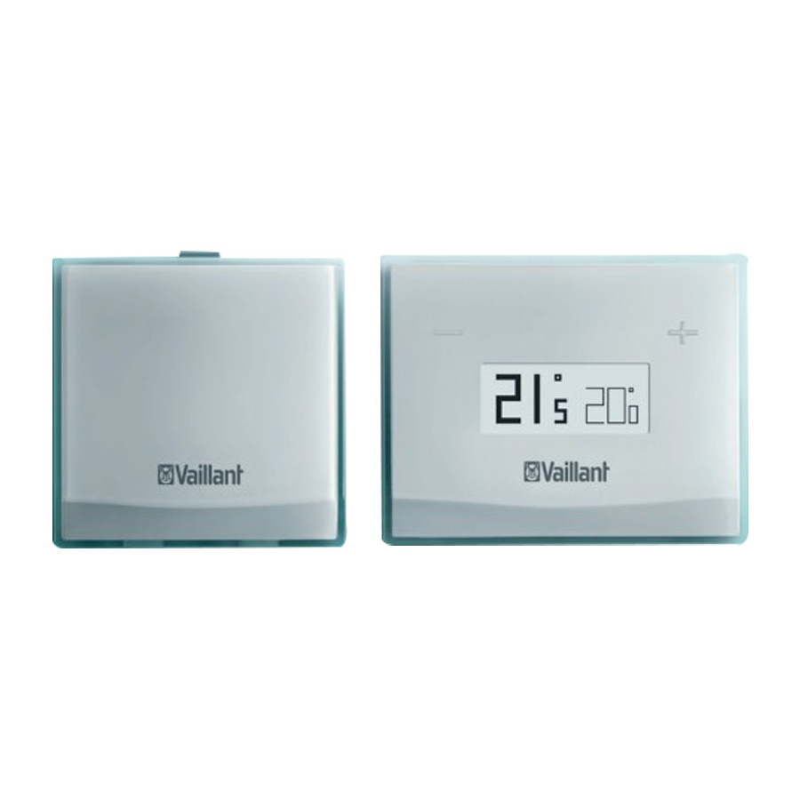
Product design

![]() and
and![]() buttons
buttons- Small wall base: Thermostat
- Wall base: Communication unit
- Bluetooth button/comfort protection mode button
- Status LED
- Communication unit
- Display
- Thermostat
- Product stand
- Large wall base: Thermostat
 and
and buttons
Information on the data plate
The data plate is attached on the rear of the communication unit and the thermostat at the factory.
| Information on the data plate | Meaning |
 | Barcode with serial number (on the communication unit only), 7th to 16th digit = product article number |
| vSMART | Product designation |
| V mA | Operating voltage and power consumption |
| LR03 | Battery type |
Set-up
Checking the scope of delivery
- Check that the scope of delivery is complete.
Scope of delivery
| Number | Designation |
| 1 | Thermostat |
| 1 | Communication unit |
| 1 | Product stand for thermostat |
| 1 | Small wall base for thermostat |
| 1 | Large wall base for thermostat |
| 1 | Wall base for communication unit |
| 1 | Power supply unit for communication unit |
| 3 | Batteries for the thermostat |
| 1 | Enclosed documentation |
| 1 | Enclosed fixing material:
|
Minimum clearances

Observing the requirements for the installation site
Communication unit
- Install the communication unit at a suitable position on the wall so that the WLAN RF connection and the RF connection to the thermostat are guaranteed.
- Install the communication unit close to a plug socket for the power supply.
- Position the communication unit in such a way that the communication unit can be connected to the boiler via an eBUS line.
Thermostat
- Choose a location for the thermostat that will allow an RF connection to be established with the communication unit.
- Position the thermostat in such a way that the room temperature can be recorded without any problems. You must observe the minimum clearances for this.
Installing the communication unit
Installing the communication unit's wall

- Remove the wall socket from the rear of the communication unit.
- Position the wall socket at a suitable location on the wall and take the cable duct for the eBUS line into consideration.
- If aneBUS line is fed out from the wall, guide the eBUS line through the cable duct for the wall socket. If no eBUS line is fed out from the wall, guide the eBUS line through the underside of the communication unit.
- Mark the drill holes.
- Drill two holes that have a diameter of 6 mm.
- Insert the supplied rawl plugs into the holes.
- Use the supplied screws to secure the wall socket to the wall.

- When you route the line from the underside of the wall socket to the eBUS connector, use the strain relief (3).
The strain relief can be adjusted to fit different cable diameters (up to a maximum of 9 mm). - Connect the eBUS line to the terminals of the eBUS plug (2) on the wall socket
- Plug the power supply unit bush into the mating connector (1) on the wall socket and route the cable through the strain relief (4).

Placing the communication unit on the wall base

- Carefully place the communication unit on the wall base.
- Carefully press the communication unit into the wall base until the locking tabs on the communication unit are heard to click into place in the wall base.
◁ The LED on the communication unit flashes blue.
Installing the thermostat
You can mount the thermostat on the wall using the wall plug (2) on the wall socket.
Installing the thermostat's wall base
Preliminary work
- Before wall-mounting the thermostat, ensure that the radio link between the thermostat and communication unit is guaranteed (see the following section).
- If the radio link is adversely affected by electrical devices or buildings, choose a different installation site for the thermostat.

- Remove the wall base from the rear of the thermostat.
- Position the wall base at a suitable location on the wall. Observe the minimum clearances.
- Mark the drill holes.
- Drill two holes that have a diameter of 6 mm.
- Insert the supplied wall plugs into the holes.
- Use the supplied screws to secure one of the two wall bases to the wall.

- If a thermostat has already been installed at the installation site and the wall breakthrough is not covered by the small wall base, use the large wall base. Otherwise, use the small wall base.
Placing the thermostat on the wall socket

- Insert batteries into the thermostat.
- Carefully place the thermostat on the wall socket.
- Carefully press the thermostat into the wall socket until the latching lugs on the wall socket audibly click into place in the thermostat.
- Check the RF connection between the thermostat and communication unit (temperature indicator on the display; see operating instructions).
- If necessary, reduce the distance between the thermostat and communication unit.
Placing the thermostat on the product stand

- Remove the wall socket from the rear of the thermostat.
- Insert batteries into the thermostat.
- Carefully place the thermostat on the product stand.
- Define the installation angle for the thermostat by placing it on the product stand at a 180° rotation.
- Carefully press the thermostat onto the product stand until the latching lugs on the product stand audibly click into the thermostat.
- Check the RF connection between the thermostat and communication unit (temperature indicator on the display; see operating instructions).
- If necessary, reduce the distance between the thermostat and communication unit.
Carrying out the electrical installation

Risk of death from live connections!
When working in the electronics box of the boiler, there is a risk of death from electric shock. The power supply terminals remain live even if the main switch is switched off.
- Switch the main switch off before working on the electronics box of the boiler.
- Disconnect the boiler from the power grid by pulling out the mains plug or by removing the power supply to the boiler using a partition with a contact gap of at least 3 mm (e. g. fuses or power switches).
- Secure the power supply against being switched back on.
- Open the electronics box only when the boiler is disconnected from the power supply.
- Disconnect the power supply to the boiler.
- Secure the power supply to the boiler against being switched back on again.
- Connect the eBUS line to the terminals (2) of the pin header connector in the wall socket of the communication unit.
- The polarity of the eBUS line is not relevant. If the eBUS line connections are switched, this does not impair communication.
- Connect the eBUS line to the terminal block of the boiler (1), as described in the instructions for the boiler.
Condition: The boiler that is to be connected has a terminal "24 V = RT".
- Make sure that the bridge is installed between the "24 V = RT" terminals.
Condition: The boiler that is to be connected has a terminal "3 4 5".
- Make sure that the bridge is installed between terminals 3 and 4.
Operating concept
The operating instructions describe the operating concept and how to operate product.
Start-up
Handing the product over to the operator
- Inform the operator how to handle the product. Answer any questions the operator may have.
- Draw special attention to the safety instructions which the operator must follow.
- To protect persons against scalding, inform the operator as follows:
- Is a cold water mixing valve integrated as protection against scalding?
- To prevent malfunctions, inform the operator of the following regulations:
- The heating installation must only be operated if it is in a perfect technical condition.
- Safety and monitoring equipment must never be removed, bridged or disabled.
- Faults and damage that adversely affect safety must be eliminated immediately by a competent person.
- The controller must not be covered by furniture, curtains or other objects.
- All radiator valves in the room in which the thermostat is installed must be fully open.
- Inform the operator that, in their absence during a frost period, the heating installation must be left in operation and the rooms must be set at a sufficient temperature in order to prevent frost damage.
- Pass all of the instructions and documentation for the product to the operator for safe-keeping.
- Tell the operator the article number of the product.
- If the operator is using underfloor heating, set the maximum target flow temperature on the boiler.
Troubleshooting
If a fault occurs, the thermostat display shows a symbol.
- Use the table in the appendix to eliminate the fault. Faults – Overview
- If you are unable to eliminate the fault, contact customer service.
Change batteries
Risk of death caused by unsuitable batteries!
If batteries are replaced with the wrong type of battery, there is a risk of explosion.
- Ensure that you use the correct battery type when replacing batteries.
- Dispose of used batteries in accordance with the instructions in this manual.


- Remove the thermostat from the product bracket or remove the product stand from the thermostat.
- Insert three new batteries (they must all be the same type). Pay attention to the correct polarity.
- Only use AAA alkaline 1.5 V batteries. Do not use rechargeable batteries.
- Place the thermostat back onto the product bracket or place the product stand back onto the thermostat. The thermostat or product stand audibly click into place.
Maintenance
Procuring spare parts
The original components of the product were also certified by the manufacturer as part of the declaration of conformity. If you use other, non-certified or unauthorised parts during maintenance or repair work, this may result in the product no longer meeting the applicable standards, thereby voiding the conformity of the product.
We strongly recommend that you use original spare parts from the manufacturer as this guarantees fault-free and safe operation of the product. To receive information about the available original spare parts, contact the contact address provided on the back page of these instructions.
- If you require spare parts for maintenance or repair work, use only the spare parts that are permitted for the product.
Customer service
For contact details for our customer service department, you can write to the address that is provided on the back page, or you can visit www.vaillant.co.uk.
Faults – Overview
| Symbol | Meaning | Remedy |
 | Batteries almost flat. | Replace the batteries in the thermostat. |
 | Batteries flat. | Replace the batteries in the thermostat. |
 | No connection to the communication unit. | Reduce the distance between the thermostat and the communication unit. |
Technical data
Technical data – Thermostat
| Power supply | 3 x 1.5 V (AAA) |
| Battery life | Approx. 2 years |
| IP rating | IP20 |
| Protection class | III |
| Pollution degree | II |
| Environmental temperature | ≤ 50 ℃ |
| Adjustable temperature range | 7 to 30 ℃ |
| Transmission frequency for thermostat – communication unit | 868 MHz |
| 868 MHz, transmission power | +10 dBm |
| 868 MHz, receiver category | 2 |
| 868 MHz, relative activation duration | < 0.1% |
| Maximum range, outdoors | 100 m |
| Maximum range, indoors | ≈ 25 m |
| Height | 83 mm |
| Width | 105 mm |
| Depth | 26 mm |
Technical data – Communication unit
| Power supply | 100 to 240 V |
| Frequency | 50/60 Hz |
| Power consumption | < 2 W |
| IP rating | IP20 |
| Protection class of the communication unit | III |
| Protection class of the power supply | II |
| Pollution degree | II |
| Environmental temperature | ≤ 50 ℃ |
| Transmission frequency for thermostat – communication unit | 868 MHz |
| 868 MHz, transmission power | +10 dBm |
| 868 MHz, receiver category | 2 |
| 868 MHz, relative activation duration | < 0.1% |
| WLAN, type | 802.11 b/g/n (2.4 GHz) |
| WLAN, transmission power | < +16 dBm |
| WLAN, supported network encryption | WEP, WPA, WPA2 |
| Bluetooth, type | 2.1 |
| Bluetooth, transmission power | +10 dBm |
| Height | 84 mm |
| Width | 83 mm |
| Depth | 25 mm |
Product data in accordance with EU Ordinance no. 811/2013, 812/2013
| Brand name | Vaillant |
| Model | vSMART |
| Temperature control class | VI |
| Contribution to the seasonal room-heating energy efficiency ɳs | 4.0% |
| All data contained in the product information has been calculated using the specifications from the European directives. Variations from product information listed at another location may be the result of different test conditions. Only the data contained in this product information is definitive and valid. | |
App
 Note The app is available as a free download (see operating instructions). Several devices that have an Internet connection can be used to access it.
Compatible with:
- At least iOS 12
- At least Android 6
Supplier
Vaillant Ltd.
Nottingham Road
Belper Derbyshire DE56 1JT
Telephone 0330 100 3143
info@vaillant.co.uk
www.vaillant.co.uk
Publisher/manufacturer
Vaillant GmbH
Berghauser Str. 40
D-42859 Remscheid
Tel. +49 2191 18 0
Fax +49 2191 18 2810
info@vaillant.de
www.vaillant.de
Documents / Resources
References
![www.vaillant.co.uk]() Vaillant UK | Leading boilers, heat pumps and heating systems
Vaillant UK | Leading boilers, heat pumps and heating systems![www.vaillant.de]() Heizung? Entdecken Sie innovative Heizungen | Vaillant
Heizung? Entdecken Sie innovative Heizungen | Vaillant
Download manual
Here you can download full pdf version of manual, it may contain additional safety instructions, warranty information, FCC rules, etc.
Advertisement


Need help?
Do you have a question about the vSMART and is the answer not in the manual?
Questions and answers