Advertisement
- 1 Foreword
- 2 Names of Parts
- 3 Touch Operation Instruction
- 4 What's Inside
- 5 As a Wireless Retro Camera Flash Trigger
- 6 As a Wireless Camera Flash Trigger
- 7 As a Wireless Outdoor Flash Trigger
- 8 As a Wireless Studio Flash Trigger
- 9 Power Switch
- 10 Channel Setting
- 11 ID Setting
- 12 Wireless Sync
- 13 Scanning Spare Channel Settings
- 14 ZOOM Setting
- 15 Sync Setting
- 16 Shooting Mode Setting
- 17 Legacy Hotshoe
- 18 Group Setting
- 19 Output Value Settings (Power Settings)
- 20 Flash Exposure Compensation Setting
- 21 Multi Flash Setting (Output, Value, Times and Frequency)
- 22 Modeling Lamp Setting
- 23 Buzz Setting
- 24 Locking Function
- 25 Setting Custom Functions
- 26 Compatible Flash Models
- 27 Compatible Camera Models
- 28 Technical Data
- 29 Firmware Upgrade
- 30 Attentions
- 31 The Reason & Solution of Not Triggering in Godox 2.4G Wireless
- 32 Caring for Flash Trigger
- 33 Important Safety Instructions
- 34 Documents / Resources
Foreword
TTL wireless flash trigger X3 O, comes with a compact size and a weight of 48g, supports TTL flash and HSS, up to 1/8000s flash sync speed. It´s not only compatible with cameras with Olympus/Panasonic hot shoes, but also can control camera flashes, outdoor flashes, studio flashes and retro flashes who have equipped with Godox 2.4GHz wireless X systems. The outstanding anti-interference capability, 32 channels together with 99 IDs ensure stable performances in complicated environment, offering more flexibility and creative possibilities for photographers.

 Do not disassemble. Should repairs become necessary, this product must be sent to our Company or an authorized maintenance center.
Always keep this product dry. Do not use in rain or damp conditions.
Keep out of reach of children.
Do not use in flammable and explosive environments. Pay attention to the relevant warning signs.
Do not leave or store the product if the ambient temperature reads over 50.
If any malfunction occurs, switch off the power immediately.
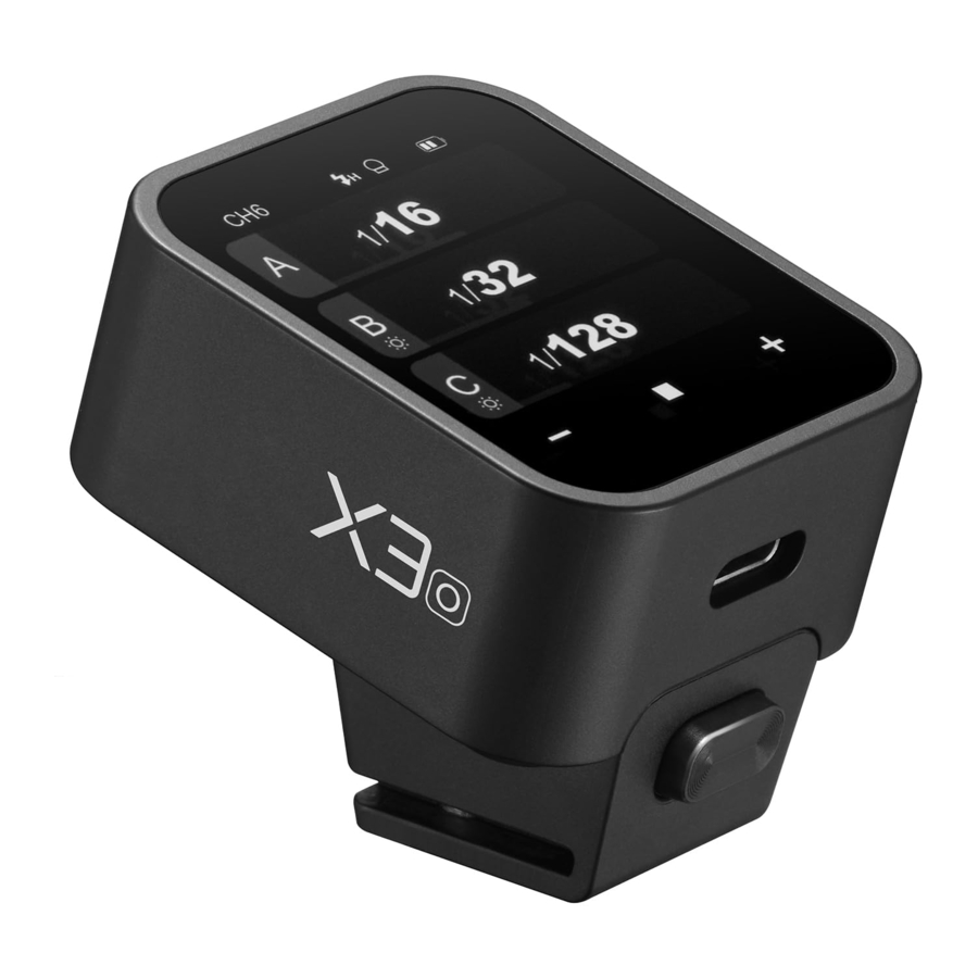
Names of Parts
Body

- Touch Screen
- Select Dial
- <
![]() > Button
> Button - Test Button
- USB-C Charging/Firmware Upgrading Port
- Installing/Detaching Button
- Mounting Slot
- Hot Shoe Camera Connection
Important Tips: If abnormalities occur, press select dial < > and test button <
  > at the same time can reset the device system, then press and hold the power switch button <
 > to restart.
When you need to detach the flash trigger, press and hold the installing/ detaching button, then grasp the hot shoe to detach it horizontally.
Display Panel

- Channel (32)
- Camera Connection
- Legacy Hotshoe
- <
![]() > means high speed sync
> means high speed sync
<![]() > means rear curtain sync
> means rear curtain sync
<![]() > means front curtain sync
> means front curtain sync - Modeling Lamp Master Control
- Buzz
- Battery Level Indicator
- Output Power Level
- Exposure Compensation Value
- Parameters <+>
- Parameters <->
- Group's Modeling Lamp
- Group
 > means high speed sync
 > means rear curtain sync
 > means front curtain sync
Multi Groups Display

Single Group Display

C.Fn. Settings Display

Touch Operation Instruction
- The parameters on the screen can be adjusted by touch operations.
- In the main interface, slide the screen up or down to check power steps or flash exposure values of multiple groups.
- If you need to switch to multi flash interface from the main interface, slide the screen down from the top to display <Multi>, press it to enter multi flash setting.
- If you need to switch to the main interface from multi flash interface, slide the screen down from the top to display <Home>, press it to enter the main interface.
- No matter in the main interface or multi flash interface, slide the screen down from the top to display <Setting>, press it to enter C.Fn. menu settings.
- In the menu interface, slide the screen from the left to the right can return to the main interface.
- In the sub menu interface, slide the screen from the left to the right can return to the previous menu interface.
- In single-group display interface, slide the screen from the left to the right can switch to multi-group display interface.
- In single-group display interface, you can switch the group by sliding the screen up or down.
- In single-group display interface, press <M> to switch to TTL auto flash mode, press <TTL> to switch to M manual flash mode.
- You can slide the progress bar to quickly adjust the power steps or flash exposure values in any interface.
- Press <-> can decrease the parameter values, press <+> can increase the parameter values.
- Press the <
![]() > can lock the screen. When the screen displays "Press for 2s to unlock", you can press and hold the screen for 2s to unlock.
> can lock the screen. When the screen displays "Press for 2s to unlock", you can press and hold the screen for 2s to unlock. - Press the <
![]() > and <
> and <![]() >, if they are lightened on means the functions are turned on, otherwise the functions are turned off.
>, if they are lightened on means the functions are turned on, otherwise the functions are turned off.
 > can lock the screen. When the screen displays "Press for 2s to
  > and <
 >, if they are lightened on means the functions are turned
 What's Inside

As a Wireless Retro Camera Flash Trigger
Take Lux Master as an example:


- Turn off the camera and mount the flash trigger on camera hot shoe. Then, power on the flash trigger and the camera.
- Slide the screen of X3 O down from the top to display <Setting>, press <Setting> to enter C.Fn. menu, then press <Wireless> to set CH and ID. Slide the screen from the left to the right to return to the main interface, on which you can set the flash mode and output power level of groups.
- Turn on the retro camera flash Lux Master, press the MENU button to enter the main interface, turn the adjust dial to wireless then press the set button to enter wireless interface.
- Slide the screen to select CH, GR or ID setting, press to enter a certain setting, then slide to set the parameters. Please set the channels and IDs of the flash and X3 O to the same.
- Press the "Wireless Sync" of the flash trigger and wireless sync icon of Lux Master can set the channels and IDs of them to the same.
- Press the camera shutter to trigger.
- Turn off the camera and mount the flash trigger on camera hot shoe. Then, power on the flash trigger and the camera.
- Slide the screen of X3 O down from the top to display <Setting>, press <Setting> to enter C.Fn. menu, then press <Wireless> to set CH and ID. Slide the screen from the left to the right to return to the main interface, on which you can set the flash mode and output power level of groups.
As a Wireless Camera Flash Trigger
Take V1 series camera flash as an example:


- Turn off the camera and mount the flash trigger on camera hot shoe. Then, power on the flash trigger and the camera.
- Slide the screen of X3 O down from the top to display <Setting>, press <Setting> to enter C.Fn. menu, then press <Wireless> to set CH and ID. Slide the screen from the left to the right to return to the main interface, on which you can set the flash mode and output power level of groups.
- Turn on the camera flash V1, press the wireless setting button and <
![]() > and <RX> icon will be displayed on the LCD panel. Press the < MENU > Button to enter the C.Fn. menu, set its channel and ID the same to the flash trigger.
> and <RX> icon will be displayed on the LCD panel. Press the < MENU > Button to enter the C.Fn. menu, set its channel and ID the same to the flash trigger.
Note: please refer to the relevant instruction manual when setting the camera flashes of other models. - Press the camera shutter to trigger.
 > and <RX> icon will be
 As a Wireless Outdoor Flash Trigger
Take AD600Pro as an example:


- Turn off the camera and mount the flash trigger on camera hot shoe. Then, power on the flash trigger and the camera.
- Slide the screen of X3 O down from the top to display <Setting>, press <Setting> to enter C.Fn. menu, then press <Wireless> to set CH and ID. Slide the screen from the left to the right to return to the main interface, on which you can set the flash mode and output power level of groups.
- Power on the outdoor flash and press the wireless setting button and the <
![]() > will be displayed on the LCD panel. Long press the <GR/CH> button to set the same channel to the flash trigger, and press the < GR/CH> button to set the same group to the flash trigger.
> will be displayed on the LCD panel. Long press the <GR/CH> button to set the same channel to the flash trigger, and press the < GR/CH> button to set the same group to the flash trigger.
Note: please refer to the relevant instruction manual when setting the outdoor flashes of other models. - Press the camera shutter to trigger.
As a Wireless Studio Flash Trigger
Take QTIII as an example:


- Turn off the camera and mount the flash trigger on camera hot shoe. Then, power on the flash trigger and the camera.
- Slide the screen of X3 O down from the top to display <Setting>, press <Setting> to enter C.Fn. menu, then press <Wireless> to set CH and ID. Slide the screen from the left to the right to return to the main interface, on which you can set the flash mode and output power level of groups.
- Connect the studio flash to power source and power it on. Press the MODE/Wireless button to make the <
![]() > displayed on the panel and enter 2.4GHz wireless mode. Press and hold the <GR/CH> button to set the same channel to the flash trigger, and press the < GR/CH > button to set the same group to the flash trigger.
> displayed on the panel and enter 2.4GHz wireless mode. Press and hold the <GR/CH> button to set the same channel to the flash trigger, and press the < GR/CH > button to set the same group to the flash trigger.
Note: please refer to the relevant instruction manual when setting the studio flashes of other models. - Press the camera shutter to trigger.
Note: As the studio flash's minimum output value is 1/32, the output value of the flash trigger should be set to or over 1/32. As the studio flash do not have TTL and multi flash functions, the flash trigger should be set to M mode in triggering.
Power Switch
Press and hold the < > button until "Godox" icon is displayed on the panel, means the device is turned on. Press and hold the <> button in power on status until the panel blacks out, then the device is turned off.
Note: In order to avoid power consumption, turn off the device when not in use. Please set the standby time (30min/60min/90min) in <Setting> — <Auto Off>. If the flash trigger is in low battery level, please charge it before put it aside.

Channel Setting

- In main interface, slide the screen down from the top to display <Setting>, press <Setting> to enter C.Fn. menu. Or you can press the <
![]() > button to display <Setting> on the panel, then press <Setting> to enter C.Fn. menu.
> button to display <Setting> on the panel, then press <Setting> to enter C.Fn. menu. - Press <Wireless> to enter wireless settings. Slide the <CH> on the left to set the channel among 1 to 32. Then slide the screen from the left to the right or press the <
![]() > button to return to the main interface.
> button to return to the main interface.
Note: Please set the flash trigger and the receiver to the same channel before usage.
ID Setting
In addition to changing the wireless transmission channel to avoid interference, we can also change the wireless ID to avoid interference.

- In main interface, slide the screen down from the top to display <Setting>, press <Setting> to enter C.Fn. menu. Or you can press the <
![]() > button to display <Setting> on the panel, then press <Setting> to enter C.Fn. menu.
> button to display <Setting> on the panel, then press <Setting> to enter C.Fn. menu. - Press <Wireless> to enter wireless settings. Slide the <ID> on the right to set the ID among OFF and 1 to 99. Then slide the screen from the left to the right or press the <
![]() > button to return to the main interface.
> button to return to the main interface.
Wireless Sync
If you need X3 O to control Lux Master to flash, then the wireless sync function can set their channels and IDs to the same quickly.
First, press the "Wireless Sync" of the flash trigger. Then, press the wireless sync icon of Lux Master.
Note: The wireless function should be turned on in order to enable wireless sync

Scanning Spare Channel Settings
Scanning spare channel function is useful to avoid interference from others' using the same channel.

- In main interface, slide the screen down from the top to display <Setting>, press <Setting> to enter C.Fn. menu. Or you can press the <
![]() > button to display <Setting> on the panel, then press <Setting> to enter C.Fn. menu.
> button to display <Setting> on the panel, then press <Setting> to enter C.Fn. menu. - Press <Wireless> to enter wireless settings. Press <SCAN> to start scanning, then six spare channels are displayed on the panel. Click the desired channel, the flash trigger will be set to that channel automatically.
ZOOM Setting

- In main interface, slide the screen down from the top to display <Setting>, press <Setting> to enter C.Fn. menu. Or you can press the <
![]() > button to display <Setting> on the panel, then press <Setting> to enter C.Fn. menu.
> button to display <Setting> on the panel, then press <Setting> to enter C.Fn. menu. - Press <
![]() > to enter ZOOM setting, slide the zoom value to adjust among Auto and 24mm to 200mm.
> to enter ZOOM setting, slide the zoom value to adjust among Auto and 24mm to 200mm.
 > to enter ZOOM setting, slide the
 Sync Setting

- In main interface, slide the screen down from the top to display <Setting>, press <Setting> to enter C.Fn. menu. Or you can press the <
![]() > button to display <Setting> on the panel, then press <Setting> to enter C.Fn. menu.
> button to display <Setting> on the panel, then press <Setting> to enter C.Fn. menu. - Press <
![]() > to enter sync setting, you can select among front curtain sync, high speed sync
> to enter sync setting, you can select among front curtain sync, high speed sync - Rear Curtain Sync: Press "OK" button on Olympus camera or "MENU" button on Panasonic camera to enter rear curtain sync mode setting. When the <
![]() > appears on the display, set the camera 2nd-C shutter.
> appears on the display, set the camera 2nd-C shutter.
 > to enter sync setting, you can
  > appears on the display, set the camera 2nd-C
 Shooting Mode Setting
- In main interface, slide the screen down from the top to display <Setting>, press <Setting> to enter C.Fn. menu. Or you can press the <
![]() > button to display <Setting> on the panel, then press <Setting> to enter C.Fn. menu.
> button to display <Setting> on the panel, then press <Setting> to enter C.Fn. menu. - Press <
![]() > to enter shooting mode setting, you can select between one-shoot mode / all-shoot mode/L-858 mode.
> to enter shooting mode setting, you can select between one-shoot mode / all-shoot mode/L-858 mode.
One-shoot Mode: In the M and Multi mode, the lead unit only sends triggering signals to the follow unit, which is suitable for one person photography for the advantage of power saving.
All-shoot Mode: The lead unit will send parameters and triggering signals to the follow unit, which is suitable for multi person photography. However, this function consumes power quickly.
 > to enter shooting mode setting, you can select between one-shoot mode /
 L-858: The flash parameters can be adjusted directly on Sekonic L-858 Light Meter when collocating with it, and the transmitter only transmits SYNC signal. The main interface will only display L-858 when it's turned on, all the parameters are unavailable to adjust since only the flash triggering function is available.

Legacy Hotshoe

- In main interface, slide the screen down from the top to display <Setting>, press <Setting> to enter C.Fn. menu. Or you can press the <
![]() > button to display <Setting> on the panel, then press <Setting> to enter C.Fn. menu.
> button to display <Setting> on the panel, then press <Setting> to enter C.Fn. menu. - Press the <
![]() > to enter the legacy hotshoe setting and choose to turn on or off. The multi mode, TTL mode and all-shoot mode are unavailable when the legacy hot shoe is turned on.
> to enter the legacy hotshoe setting and choose to turn on or off. The multi mode, TTL mode and all-shoot mode are unavailable when the legacy hot shoe is turned on. - The legacy hotshoe icon <
![]() > will display on the main interface when it's turned on, then it means the legacy hotshoe function is available.
> will display on the main interface when it's turned on, then it means the legacy hotshoe function is available.
 > to enter the legacy hotshoe setting
 Note:
- Not all the cameras support legacy hot shoe function.
- The flashes may be out of sync if you trigger at high speed shutter in legacy hotshoe mode.
Group Setting
- Group Selection
In main interface, slide the screen to the bottom until <![]() > is displayed on the panel, press the icon to enter group selection setting, you can select group among A to F and 0 to 9.
> is displayed on the panel, press the icon to enter group selection setting, you can select group among A to F and 0 to 9.
Note: Group A-E can be set to TTL auto flash mode or M manual flash mode, while group F/0-9 is set to M manual flash mode by default.

- Multi-group Display
The main interface will display multi-group parameters after group selection, you can check output power of each group.
![]()
- Single-group Display
In main interface, press the output power of a certain group to enter more settings such as power level, flash mode and modeling lamp of that group.
In single-group display interface, you can switch the group by sliding the screen up or down.
![]()


Output Value Settings (Power Settings)
Multi-group display in M mode
Press <+> to increase output power levels of multi-group at the same time, press <-> to decrease output power levels of multi-group at the same time, which will change from Min. to 1/1 or from Min. to 10 in 0.1 or 1/3 step increments. The output power levels of multi-group can not be increased or decreased at the same time if a certain group has already reached the lowest or highest power level. You can also slide the progress bar to quickly adjust the output power.

Single-group display in M mode
Press <+> to increase output power level of a certain group, press <-> to decrease output power level of a certain group, which will change from Min. to 1/1 or from Min. to 10 in 0.1 or 1/3 step increments. You can also slide the progress bar to quickly adjust the output power.
Note: M eans manual flash mode.
Note: Min. refers to the minimum value that can be set in M or multimode. The minimum value can be set to 1/128, 1/256, 1/512, 3.0, 2.0 or 1.0

Flash Exposure Compensation Setting
Multi-group display in TTL mode
Press <+> to increase FEC values of multi-group at the same time, press <-> to decrease FEC values of multi-group at the same time, which will change from -3 to 3in 1/3 step increments. You can also slide the progress bar to quickly adjust the FEC values.
The FEC values of multi-group can not be increased or decreased at the same time if a certain group has already reached the lowest or highest FEC value.

Single-group display in TTL mode
Press <+> to increase FEC value of a certain group, press <-> to decrease FEC value of a certain group, which will change from -3 to 3 in 1/3 step increments. You can also slide the progress bar to quickly adjust the FEC value.
Note: TTL means auto flash mode.

Multi Flash Setting (Output, Value, Times and Frequency)
In main interface, slide the screen down from the top to display <Multi>, press it to enter multi flash setting. Or you can press <> button to make the panel display <Multi>, then press it to enter multi flash setting.
")
- Output Power (Min. ~ 1/4 or Min. ~ 8.0)
Press <+> to increase output power level, press <-> to decrease output power level, which will change from Min. to 1/4 or from Min. to 8.0 in integer steps. You can also slide the progress bar to quickly adjust the output power. - Flash Times
Slide the left column <Times> to adjust flash times from 1 to 100. - Flash Frequency (Hz)
Slide the right column <Hz> to adjust flash frequency from 1 to 199. - Group A/B/C/D/E
You can select a certain group or multi groups (five groups at most).
Note:
- As flash times are restricted by flash output value and flash frequency, the flash times can not surpass the upper value that permitted by the system. The times that transported to the receiver end are real flash time, which is also related to the camera's shutter setting.
- Min. refers to the minimum value that can be set in M or multi mode. The minimum value can be set to 1/128, 1/256, 1/512, 3.0, 2.0 or 1.0.
Modeling Lamp Setting
- When displaying multiple groups, slide the screen down from the top to display <
![]() >, press it to control the ON/OFF of the modeling lamp.
>, press it to control the ON/OFF of the modeling lamp.
Note: If the modeling lamp of a certain group is off, then it can not be turned on or off along with other groups.
![]()
- When displaying a single group, you can press <
![]() > to switch among 3 statuses: <
> to switch among 3 statuses: < ![]() > off, <
> off, < ![]() > on, or <
> on, or <![]() > PROP auto mode.
> PROP auto mode.
Note: When the modeling lamp is set to PROP auto mode, its brightness will be change along with the brightness of the flash. When the modeling lamp is on, press <+> to increase its brightness value, press <-> to decrease its brightness value, or you can also slide the progress bar to quickly adjust the brightness from 10 to 100.
Note: The models that can use the modeling lamp are as follows: GSII, SKII, SKIIV, QSII, QDII, DEII, DPII series, DPIII series, etc. The outdoor flash AD200 and AD600 can use this function after upgrade. The new arrivals with modeling lamps can also use this function.
![]()
 >, press it to


Buzz Setting
In main interface, slide the screen down from the top to display <  >, or you can press <> button to make the panel display < >, then press to turn on or off the buzz function.
< > means the buzz function of controlled flash is on.
<  > means the buzz function of controlled flash is off.

Locking Function
In main interface, slide the screen down from the top to display <  >, or you can press <> button to make the panel display < >, then press to lock the screen. When the screen displays "Press for 2s to unlock", means the screen is locked and operations are unavailable, you can press and hold the screen or the select dial for 2s to unlock the screen.

Setting Custom Functions
In main interface, slide the screen down from the top to display <Setting>, press it to enter custom function settings. Or you can press < > button to make the panel display < Setting >, then press it to enter custom function settings. The following table lists the available and unavailable custom functions of this flash:


Compatible Flash Models
| Flash Trigger | Receiver | Flash Models | Note |
| X3 O | - | AD2400P, AD1200PRO, AD600 Series, AD360II Series, AD200 Series, V860II Series, V860III Series, V850 Series, TT685 Series, TT685II Series, TT585 Series, FV Series, V1 Series, Quicker II Series, Quicker III Series, SKII Series, SKII-V Series, DPII Series, DPIII Series, GS/DSII Series, TT350O, V350O, AD300Pro, AD400Pro, AD100Pro, V1Pro Series, Lux Master |
Note: The range of support functions: the functions that are both owned by X3 O and flash.
Compatible Camera Models
This flash trigger can be used on the following camera models:
Olympus: PEN-F,E-P3,E-P5,E-PL5,E-PL6,E-PL7,E-PL8,E-M1,E-M10II,E-M10III
Panasonic: DMC-G85,DMC-GH4,DMC-GF1,DMC-GX85,DMC-LX100,DMC-FX2500GK
- This table only lists the tested camera models not all Olympus/Panasonic cameras. For the compatibility of other camera models, a self-test is recommended.
- Rights to modify this table are retained.
Technical Data

Firmware Upgrade
This flash trigger supports firmware upgrade through the USB-C port. Update information will be released on our official website.
As the firmware upgrade needs the support of Godox G3 V1.1 software, please download and install the "Godox G3 V1.1 firmware upgrade software" before upgrading. Then, choose the related firmware file.
Upgrading instruction: In power-on status, connect X3 O to the computer through USB-C cable, and click "Firmware Upgrade" to enter upgradation after it shows on the screen. In power-off status, press and hold the adjust dial and connect X3 O to the computer through USB-C cable to enter the firmware upgrade.
Note: Please obtain the latest electronic instruction manual on our official website for there may be upgraded firmware. The transmitter screen will turn black if abnormalities occur in upgrading. The solution is to re-plug the USB cable, press and hold the test button and the select dial at the same time, then release the test button only, until "Upgrading" appears on the interface, then the device can be upgraded successfully through USB cable.
Attentions
- Unable to trigger flash or camera shutter. Make sure power switch is turned on. Check if the flash trigger and the receiver are set to the same channel, if the hot shoe mount or connection cable is well connected, or if the flash triggers are set to the correct mode.
- Camera shoots but does not focus. Check if the focus mode of the camera or lens is set to MF. If so, set it to AF.
- Signal disturbance or shooting interference. Change a different channel on the device.
The Reason & Solution of Not Triggering in Godox 2.4G Wireless
- Disturbed by the 2.4G signal in outer environment (e.g. wireless base station, 2.4G wifi router, Bluetooth, etc.)
![]() To adjust the channel CH setting on the flash trigger (add 10+ channels) and use the channel which is not disturbed. Or turn off the other 2.4G equipment in working
To adjust the channel CH setting on the flash trigger (add 10+ channels) and use the channel which is not disturbed. Or turn off the other 2.4G equipment in working - Please make sure that whether the flash has finished its recycle or caught up with the continuous shooting speed or not (the flash ready indicator is lightened) and the flash is not under the state of over-heat protection or other abnormal situation.
![]() Please downgrade the flash power output. If the flash is in TTL mode, please try to change it to M mode (a preflash is needed in TTL mode)
Please downgrade the flash power output. If the flash is in TTL mode, please try to change it to M mode (a preflash is needed in TTL mode) - Whether the distance between the flash trigger and the flash is too close or not (<0.5m).
![]() Please turn on the "close distance wireless mode' on the flash trigger.
Please turn on the "close distance wireless mode' on the flash trigger.
![]() Please set the triggering distance to 0-30m
Please set the triggering distance to 0-30m - Whether the flash trigger and the receiver end equipment are in the low battery states or not
![]() Please charge or replace the battery in time.
Please charge or replace the battery in time.
 To adjust the channel CH setting on the flash trigger (add 10+ channels) and use the channel which is not disturbed. Or turn off the other 2.4G equipment in working
Caring for Flash Trigger
Avoid sudden drops. The device may fail to work after strong shocks, impacts, or excess stress.
Keep dry. The product isn't water-proof. Malfunction, rust, and corrosion may occur and go beyond repair if soaked in water or exposed to high humidity.
Avoid sudden temperature changes. Condensation happens if sudden temperature changes such as the circumstance when taking the transceiver out of a building with higher temperature to outside in winter. Please put the transceiver in a handbag or plastic bag beforehand.
Keep away from strong magnetic field. The strong static or magnetic field produced by devices such as radio transmitters leads to malfunction.
Changes made to the specifications or designs may not be reflected in this manual.
Operating frequency: 2412.99MHz – 2464.49MHz
Maximum EIRP Power: 9.52dBm
Important Safety Instructions
This product is a professional photographic equipment, to be operated by professional personnel only.
The following basic safety precautions must be followed when using this product:
All transport protective materials and packaging on the product must be removed before use.
- Carefully read and fully understand the instruction manual before use and strictly follow the safety instructions.
- Dot not use damaged equipment or accessories. Allow professional repair technicians to inspect and confirm normal operation before continuing use after repairs.
- Please disconnect the power when not in use.
- This device is not waterproof. Keep it dry and avoid immersing it in water or other liquids. It should be installed in a ventilated and dry location and avoid using in rainy, humid, dusty, or overheated environments. Do not place items above the device or allow liquids to flow into it to prevent danger.
- Do not disassemble without authorization. If the product malfunctions, it must be inspected and repaired by our company or authorized repair personnel.
- Do not place the device near alcohol, gasoline, or other flammable volatile solvents or gases such as methane and ethane.
- Do not use or store this device in potentially explosive environments.
- Clean gently with a dry cloth. Do not use a wet cloth as it may damage the device.
- This instruction manual is based on rigorous testing. Changes in design and specifications are subject to change without notice. Check official website for latest instruction manual and product updates.
- Use only specified charger and follow proper usage instructions for products with built-in lithium batteries, within the rated voltage and temperature range.
- The product is powered by lithium battery, who has limited lifespan and will gradually lose its charging capacities, which is irreversible. As the battery ages, the product's battery life will decrease. The lifespan of lithium battery is estimated to be 2 to 3 years. Please regularly check the battery, and if the charging time significantly increases or the battery life significantly decreases, consider replacing the battery.
- The warranty period for this device as a whole is one year. Consumables (such as batteries), adapters, power cords, and other accessories are not covered by the warranty.
- Unauthorized repairs will void the warranty and will incur charges.
- Failures from improper operation is not covered under warranty.
Documents / ResourcesDownload manual
Here you can download full pdf version of manual, it may contain additional safety instructions, warranty information, FCC rules, etc.
Advertisement


Need help?
Do you have a question about the X3 O and is the answer not in the manual?
Questions and answers