Advertisement
Table of Contents
- 1 Table of Contents
- 2 Programming
- 3 Control Inputs
- 4 Serial Port
- 5 Other Inputs
- 6 Test Pushbutton
- 7 Close Speed
- 8 Programming Examples
- 9 Learning Phase of the Door Operator
- 10 Troubleshooting During the Autoadjustment
- 11 Test of the Photocell
- 12 Troubleshooting
- 13 Declaration of Conformity
- Download this manual
Advertisement
Table of Contents
Troubleshooting

Related Manuals for Fermator VF5


Summary of Contents for Fermator VF5
- Page 1 Instructions DOC-FE.IE.IN.014VF5.EN VF5 Electronic Module Version: 0.00 VF5 Electronic Module • Ctra. Constantí km.3 • 43206 Reus, Spain Pág. 1 / 17 Tecnolama s.a. Tel. +34 977 774 065 • Fax. +34 977 771 615 • www.fermator.com • NIF. A-43128784...
-
Page 2: Table Of Contents
Instructions DOC-FE.IE.IN.014xxx.EN VF5 Electronic Module Version: 0.0 INDEX ● CONNECTIONS......................................3 ● PROGRAMMING.......................................4 ● INPUTS........................................5 ● PROGRAMMING EXAMPLES...................................9 ● LEARNING PHASE OF THE DOOR OPERATOR ..........................10 ● TROUBLESHOOTING DURING THE AUTOADJUSTMENT........................11 ● TEST OF THE PHOTOCELL...................................12 ● NORMAL REGULATION WITH THE LIFT CONTROLLER........................13 ●... - Page 3 Instructions DOC-FE.IE.IN.014xxx.EN VF5 Electronic Module Version: 0.0 • Ctra. Constantí km.3 • 43206 Reus, Spain Pág. 3 / 17 Tecnolama s.a. Tel. +34 977 774 065 • Fax. +34 977 771 615 • www.fermator.com • NIF. A-43128784...
-
Page 4: Programming
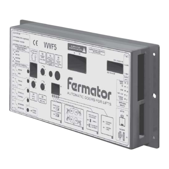
The VF may be programmed using the DIP switches on the front of the unit. If any change is made to any of the above switch selections, the main supply of the VF5 unit MUST be switched OFF and ON again to read the new programming. The switches functions are: 1 &... -
Page 5: Control Inputs
Instructions DOC-FE.IE.IN.014xxx.EN VF5 Electronic Module Version: 0.0 INPUTS POWER INPUTS 230 VOLTS SINGLE PHASE AC (5, 6, 7) The circuit has been designed to operate on a mains supply of 230 V AC (+10%,-15%, 50 or 60 Hz). The unit will consume on average approximately 1 ampere from the supply. -
Page 6: Other Inputs
VF5 Electronic Module Version: 0.0 PHOTOCELL (17, 18, 19, 20) One of the most relevant characteristics of this control is the optional incorporation of the Fermator photocell. It is composed by a emitter and receptor infrared. OTHER INPUTS (26, 21, 25, 23) 26.-... -
Page 7: Test Pushbutton
The doors will open slowly for the first operation after power has been removed from the door control unit. Autoadjustment only needs to be used when setting the initial parameters or when changes such as connecting or removing the Fermator photocell are made. Autoadjustment process: ... -
Page 8: Close Speed
Compatibility with Fermator asynchronous motor. The VF5+ encoder connector is prepared to connect the high resolution encoder for the synchronous PM motor (5 wires) and the standard encoder from the asynchronous motor (4 wires). -
Page 9: Programming Examples
Instructions DOC-FE.IE.IN.014xxx.EN VF5 Electronic Module Version: 0.0 PROGRAMMING EXAMPLES MASTER: 1 INPUT Configuration 1. ON: 1 Input. 2. Depends on type of door. 3. Depends on type of door. 4. ON: Master. Inputs 1. (8) Close. Closes the doors with voltage between terminals 8 &... -
Page 10: Learning Phase Of The Door Operator
Instructions DOC-FE.IE.IN.014xxx.EN VF5 Electronic Module Version: 0.0 LEARNING PHASE OF THE DOOR OPERATOR 1.- Switch on the VF door controller. - Button O/I in the side of the box. 2.- Cables. - Connect the 230V AC mains supply to the controller (#5, #6, #7). -
Page 11: Troubleshooting During The Autoadjustment
The motor voltage has to be checked with the Fermator programming tool. You should change the motor if no movement is made when the voltage is present. - Page 12 - Press the «TEST» button and establish the potentiometers (open speed, close speed and the safety force) in order to get the required adjustment. Information: The VF parameters could be adjusted with the Fermator programming tool. • Ctra. Constantí km.3 •...
-
Page 13: Test Of The Photocell
Instructions DOC-FE.IE.IN.014xxx.EN VF5 Electronic Module Version: 0.0 TEST OF THE PHOTOCELL Remove the photocell wiring from any place where there are “electric noises” such as motors, supplies wiring, etc. 1.- Verify that there is an emitter and a receiver (E mark and R mark on the capsules) connected to the correct cable (emitter to the yellow cable and receiver to the green one). -
Page 14: Troubleshooting
Adjust the belt tension and make the autoadjustment again. • The system gets power but doesn’t work and the led ON is off. - Check if the external fuse is burned and change it for another Fermator fuse (250 V, 4 A ceramic fast speed). - Page 15 Instructions DOC-FE.IE.IN.014xxx.EN VF5 Electronic Module Version: 0.0 CHARACTERISTICS PAGE POWER SUPPLY: AC voltage range: 230 V AC +10%, -15%. Frequency supply: 50...60 Hz. Stand by power: 50 mA 4 W. Nominal power (PM motor): 0,21 A 20 W.
- Page 16 Instructions DOC-FE.IE.IN.014xxx.EN VF5 Electronic Module Version: 0.0 PERFORMANCE: Open Speed: 200...700 mm/s. Close speed: 150...400 mm/s. Maximum acceleration: 800...1500 mm/s Safety force: 60...150 N adjustable. Maintenance torque (Opened Door): 80 N/ cm. • Ctra. Constantí km.3 •...
-
Page 17: Declaration Of Conformity
Instructions DOC-FE.IE.IN.014xxx.EN VF5 Electronic Module Version: 0.0 DECLARATION OF CONFORMITY Tecnolama, S.A. Ctra. Constantí Km. 3 43206 REUS (España) Herewith declares that the products mentioned below conform with the following E.U. council directives: European Directive 2014/30/EU on Electromagnetic Compatibility (EMC)
Need help?
Do you have a question about the VF5 and is the answer not in the manual?
Questions and answers