
Related Manuals for SUTO iTEC S120-Ambient


Summary of Contents for SUTO iTEC S120-Ambient
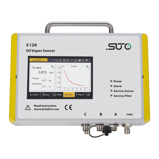
- Page 1 English Instruction and Operation Manual S120-Ambient Oil Vapor Monitor for Ambient Measurement...
- Page 2 The device is designed exclusively for the described application. SUTO offers no guarantee for the suitability for any other purpose. SUTO is also not liable for consequential damage resulting from the delivery, capability or use of this device. Revision: 2024-1 Last modifications: December, 2024 S120-Ambient...
-
Page 3: Table Of Contents
9.2 Main menus................20 9.3 Sensor settings ..............21 9.3.1 Basic setting..............21 9.3.2 Analog output ...............22 9.3.3 Alarm settings...............22 9.3.4 Status................23 9.4 Guided Measurement with PDF Report Generation....23 9.5 Files...................24 9.6 Service info ................24 9.7 System settings ..............25 9.8 Communication ..............26 S120-Ambient... - Page 4 10.1 Steps for guided measurement..........29 10.2 Report for guided measurements.........32 11 Troubleshooting...............33 11.1 LED indicators..............33 11.2 Error indications..............34 12 Signal outputs.................35 12.1 Analog output ..............35 12.2 Modbus interface ...............35 12.3 Alarm output ..............38 13 Calibration................39 14 Maintenance................39 15 Disposal or waste..............39 16 Warranty................39 S120-Ambient...
-
Page 5: Safety Instructions
• Consider all regulations for electrical installations. • The system must be disconnected from any power supply during maintenance work. • Any electrical work on the system is only allowed by authorized qualified personnel. S120-Ambient... - Page 6 • Please make sure that the storage temperature of the device is between -20 ... +50°C. • Avoid direct UV and solar radiation during storage. • For the storage the humidity must be <90%, no condensation. S120-Ambient...
-
Page 7: Registered Trademarks
• PID sensor for the highest accuracy. • Service and alarm indication through LEDs. • Connectable to display and data logger of SUTO iTEC as well as third-party display and control units. • IP65 casing provides robust protection in rough industrial environment. -
Page 8: Technical Data
IP65 Dimensions See dimensional drawing on page 10. Display 5” graphic display with touch interface and data logger Interface USB, Modbus/RTU (RS-485), Modbus/TCP (Ethernet) Weight 2.4 kg UV lamp lifetime 6,000 working hours or 1 year, whichever comes first S120-Ambient... -
Page 9: Electrical Data
S120 to obtaining accurate results. Oil vapor concentration Input pressure ≤ 0.1 mg/m 0.1 ~ 5 mg/m 3 bar 70 min 30 min 7 bar 45 min 20 min 15 bar 45 min 20 min S120-Ambient... -
Page 10: Dimensional Drawings
6 Dimensional drawings 6 Dimensional drawings Dimensional drawings of S120-Ambient in mm Dimensional drawing of the funnel with stand in mm S120-Ambient... -
Page 11: Installation
Instruction manual Calibration certificate 7.1 Installation requirements The S120-Ambient can be used as a portable device or fixedly installed. The device is not suitable for permanent outside installations. Use always the supplied stand to place the funnel in the ambient and make sure the area in front of the funnel is free of any obstacles which could lead to wrong measurements. - Page 12 7 Installation Method 1. Method 2. S120-Ambient...
-
Page 13: Air Connections
7 Installation 7.3 Air connections The air inlet and outlet are located at the bottom of the S120-Ambient, as shown below. Follows the steps to connect the S120-Ambient with the funnel for air collection. 1. Connect the hose to the inlet of the S120-Ambient. -
Page 14: Electrical Connections
7 Installation measurement result: • All components from the sampling point to the S120-Ambient must be oil- and grease-free. • Ambient and gas temperature must be within the specified ranges stated in section 5.2 General data. • The sampling air mus be dry (<= 60% rH) and clean. -
Page 15: Pin Assignment Of M12 Connectors
Connect the M12-A or M12-B connector to the power supply provided in the pacage. 7.4.3 RS-485 networking (Modbus/RTU) When output signal is carried over the Modbus/RTU protocol, connect the S120-Ambient to the RS-485 network through the M12-A or M12-C connector. S120-Ambient... -
Page 16: Tcp/Ip Networking (Modbus/Tcp)
7 Installation 7.4.4 TCP/IP networking (Modbus/TCP) When the Modbus/TCP protocol is applied, connect the S120-Ambient to the TCP/IP network through the RJ-45 connector. Remove the protection cap and plug in the network cable (RJ-45). 7.4.5 Connection to the SUTO iTEC display units... -
Page 17: Configuration
Transmission mode = RTU Modbus/TCP : Device address = last two digits of the serial number IP Configuration = DHCP You can use one of the following ways to configure S120-Ambient. 8.1 Local display See Chapter 9 Operations using the integrated display. -
Page 18: Operations Using The Integrated Display
9 Operations using the integrated display 9 Operations using the integrated display The S120-Ambient is equipped with an integrated display, you can configure the device by using the display. This chapter describes the usage of the display and provides instructions on how to configure the device. -
Page 19: Quick Buttons
Description of icons displayed in the status bar. USB stick connected System error Sensor connection has Sensor unit is not changed, not matching matching with with configuration configuration RTC backup battery Logger status status Sensor calibration is Alarm triggered expired S120-Ambient... -
Page 20: Main Menus
After you click the Menu button, the following screen appears displaying all operating menus. The main menus and their functions are described below. Sensor settings To view and check the S120-Ambient settings. Location setting Settings are fixed. Guided To start the guided measurements, which lead measurement you through a complete measurement process. -
Page 21: Sensor Settings
9 Operations using the integrated display 9.3 Sensor settings To configure sensor settings before starting measurement. After you changes settings, click “Save” to have the changes saved in the S120-Ambient. 9.3.1 Basic setting Altitude Enter the Altitude. To obtain an accurate oil vapor measurement, you must input your altitude. -
Page 22: Analog Output
9.3.2 Analog output To configure the scaling of analog output. Whenever the output unit is changed, it is recommended to adjust the scaling of the analog output. 9.3.3 Alarm settings To configure the threshold of oil vapor that triggers the alarm. S120-Ambient... -
Page 23: Status
9.4 Guided Measurement with PDF Report Generation To start the different measurement and monitoring according to your requirement. The recorded file and report can be viewed after the measurement is done. For more information, see Chapter 10 Guided Measurement. S120-Ambient... -
Page 24: Files
9 Operations using the integrated display 9.5 Files To view and manage all recorded measurement files and screenshots. To view the available memory. 9.6 Service info To view the contact information of the company that provides the service. S120-Ambient... -
Page 25: System Settings
9 Operations using the integrated display 9.7 System settings To view and change S120-Ambient system-level settings. Password To set the password to protect some critical operations from unauthorized access. Back light To adjust brightening and dimming time out. Calibrate touch screen To calibrate touch accuracy... -
Page 26: Communication
9 Operations using the integrated display 9.8 Communication To configure the field bus RS-485 and Ethernet Modbus/TCP. 9.8.1 Modbus/RTU settings To change the Modbus/RTU settings. S120-Ambient... -
Page 27: Modbus/Tcp Settings
9 Operations using the integrated display 9.8.2 Modbus/TCP settings To change the Modbus/TCP settings. S120-Ambient... -
Page 28: Guided Measurement
10 Guided Measurement 10 Guided Measurement The S120-Ambient provides a software-based guided measurement which takes you through the complete measurement. This leads to a simplified measurement process and prevents you from wrong measurements. Finally, a PDF report can be created from the measurement series. -
Page 29: Steps For Guided Measurement
Report Manager. For more information, see section 10.2 Report for guided measurements. 10.1 Steps for guided measurement After you start a guided measurement, follow below steps to go through the whole process. 1. An overview is given about the selected measurement types. Click Yes to start. S120-Ambient... - Page 30 If the altitude is negative, enter 0 instead of the real negative value. 4. Select the compressed air class as needed. Note: ISO8573 stipulates alarm limit values for different classes. CLASS 0 allows you to customize the alarm limit values. S120-Ambient...
- Page 31 See section 5.6 for the minimum measurement time. 7. The system checks whether the compressed air is connected and the pressure is within the valid range. Click Start to start the measurement. S120-Ambient...
-
Page 32: Report For Guided Measurements
(not the check box on the right). A window appears showing the PDF for your preview. • To copy, export or delete files, select the file check boxes, and then click the corresponding button at the bottom. S120-Ambient... -
Page 33: Troubleshooting
Copy raw Copies the raw measurement data to the USB stick (*.csd). data to 11 Troubleshooting This chapter describes how to troubleshoot S120-Ambient based on error indications such as LED indicators, relay status, and current output. 11.1 LED indicators Indicates the power status. -
Page 34: Error Indications
11 Troubleshooting 11.2 Error indications This table lists the main error indications with S120-Ambient and the corresponding instructions to locate and fix errors. When the alarm LED is on: 1. Measure the current output and relay status. 2. Refer to the following table to proceed. -
Page 35: Signal Outputs
12 Signal outputs 12 Signal outputs 12.1 Analog output The S120-Ambient has an analog output range of 4 ... 20 mA. This output is scaled to: • 4 mA = 0.000 mg/m • 20 mA = 5.000 mg/m 12.2 Modbus interface... - Page 36 Byte0-Byte1-Byte2-Byte3 for the correct display of the value. Modbus holding registers (read-only) Modbus Data Data register Channel description Unit Resolution type length address FLOAT 4-Byte Gas temperature °C mg/m FLOAT 4-Byte Oil vapor content 0.001 FLOAT 4-Byte Pressure S120-Ambient...
- Page 37 The following table lists specifications of the Modbus/TCP output channels in this sensor. Channel Data Func Holding Unit Resolution Length Description type Code register Oil vapor mg/m³ 0.001 FLOAT_L 4-byte Pressure 0.01 FLOAT_L 4-byte Temperature °C 0.01 FLOAT_L 4-byte Serial number UINT32_L 4-byte (sensor) S120-Ambient...
-
Page 38: Alarm Output
12 Signal outputs 12.3 Alarm output The S120-Ambient provides a relay alarm output. This output enables you to monitor such as the oil vapor content and gives an alarm at a particular threshold value. Alarm relay specifications: Rating: 40 VDC / 0.2 A... -
Page 39: Calibration
Please find the warranty as a separated warranty card included with the instrument delivery. The warranty does not cover any wear parts or consumables, therefore the UV lamp with limited lifetime as well as the internal filter are not covered by the warranty. S120-Ambient... - Page 40 16 Warranty SUTO iTEC GmbH SUTO iTEC (ASIA) Co., Ltd. Grißheimer Weg 21 Room 10, 6/F, Block B, Cambridge Plaza D-79423 Heitersheim 188 San Wan Road, Sheung Shui, N.T. Germany Hong Kong Tel: +49 (0) 7634 50488 00 Tel: +852 2328 9782 Email: sales@suto-itec.com...
Need help?
Do you have a question about the S120-Ambient and is the answer not in the manual?
Questions and answers