Pioneer X-MDX707 Service Manual

Pioneer X-MDX707 Service Manual

Md/cd component system

Advertisement

Quick Links

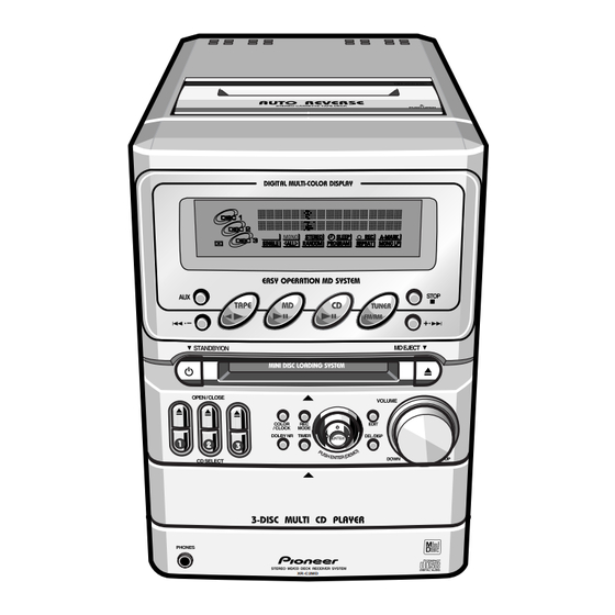
MD/CD COMPONENT SYSTEM
X-MDX707
XR-C2MD
THIS MANUAL IS APPLICABLE TO THE FOLLOWING MODEL(S) AND TYPE(S).
Model
Type
XR-C2MD
LBWXJ
NLWXJ/HK
¶ X-MDX707 is combination of the following components.
¶ For speaker system S-C2-LR, refer to the service manual RRV2156.
Component
STEREO MD/CD CASSETTE DECK RECEIVER
SPEAKER SYSTEM
CONTENTS
1. SAFETY INFORMATION ...................................... 2
4. PCB CONNECTION DIAGRAM ......................... 40
5. PCB PARTS LIST ............................................... 54
6. ADJUSTMENT .................................................... 60
PIONEER CORPORATION
PIONEER ELECTRONICS SERVICE, INC. P.O. Box 1760, Long Beach, CA 90801-1760, U.S.A.
PIONEER ELECTRONIC (EUROPE) N.V. Haven 1087, Keetberglaan 1, 9120 Melsele, Belgium
PIONEER ELECTRONICS ASIACENTRE PTE. LTD. 253 Alexandra Road, #04-01, Singapore 159936
c
PIONEER CORPORATION 1999
Power Requirement
AC110V
AC220V
Model
X-MDX707
XR-C2MD
S-C2-LR
4-1, Meguro 1-chome, Meguro-ku, Tokyo 153-8654, Japan
XR-C2MD
Service manual
RRV2165
This manual.
RRV2156
7. GENERAL INFORMATION ................................ 68
7.1 DIAGNOSIS .................................................. 68
7.1.1 TROUBLESHOOTING ........................... 68
7.1.2 DISASSEMBLY/ASSEMBLY .................. 78
7.2 PARTS .......................................................... 86
7.2.1 IC ............................................................ 86
7.2.2 DISPLAY ................................................. 90
T - ZZK AUG. 1999 Printed in Japan
ORDER NO.
RRV2165
Remarks
Remarks

Advertisement

Table of Contents
loading
Need help?

Need help?

Do you have a question about the X-MDX707 and is the answer not in the manual?

Questions and answers

Subscribe to Our Youtube Channel

Summary of Contents for Pioneer X-MDX707

  • Page 1: Table Of Contents

    PIONEER CORPORATION 4-1, Meguro 1-chome, Meguro-ku, Tokyo 153-8654, Japan PIONEER ELECTRONICS SERVICE, INC. P.O. Box 1760, Long Beach, CA 90801-1760, U.S.A. PIONEER ELECTRONIC (EUROPE) N.V. Haven 1087, Keetberglaan 1, 9120 Melsele, Belgium PIONEER ELECTRONICS ASIACENTRE PTE. LTD. 253 Alexandra Road, #04-01, Singapore 159936 PIONEER CORPORATION 1999 T –...
  • Page 2: Safety Information

    LABEL CHECK IMPORTANT THIS PIONEER APPARATUS CONTAINS LASER OF CLASS 1. SERVICING OPERATION OF THE APPARATUS S H O U L D B E D O N E B Y A S P E C I A L L Y INSTRUCTED PERSON.
  • Page 3: Exploded Views And Parts List

    AZA7331 • • • • • • • • • • • • • • • (2) CONTRAST TABLE X-MDX707/LBWXJ and NLWXJ/HK are constructed the same except for the following : Part No. Mark No. Symbol and Description X-MDX707 X-MDX707...
  • Page 4 X-MDX707, XR-C2MD 2.2 UNIT ASSY (1/2) Refer to "2.4 TOP PANEL ASSY". Refer to "2.5 MD UNIT". Insulation Plate CONTROL Refer to "2.2 UNIT ASSY (2/2)". POP Label Refer to "2.3 FRONT UNIT".
  • Page 5 X-MDX707, XR-C2MD (1) UNIT ASSY (1/2) PARTS LIST Mark No. Description Part No. Screw CCZ30P060FMC Screw BBZ30P080FZK Rear Panel 4707810001 Side Panel L 4707814001 Side Panel R 4707815001 Tray Panel 4707807001 Rear Label See Contrast table (2) Screw BBT30P080FNI CONTROL Unit...
  • Page 6 X-MDX707, XR-C2MD 2.3 UNIT ASSY (2/2) DI PCB IC PCB Double Face AMP PCB Double Face Refer to "2.10 CD MECHA". PS PCB...
  • Page 7 X-MDX707, XR-C2MD (1) UNIT ASSY (2/2) PARTS LIST Mark No. Description Part No. Mark No. Description Part No. Cord Bushing 0064695000 CD Unit 4707030000 Screw BBZ30P080FZK PT Screw P2006SK 0972920065 Rubber Foot 4701881000 Screw BPZ26P100FMC AMP Unit 4707001000 Screw BPZ30P120FMC...
  • Page 8 X-MDX707, XR-C2MD 2.4 FRONT UNIT SW PCB...
  • Page 9 X-MDX707, XR-C2MD • FRONT UNIT PARTS LIST Mark No. Description Part No. Mark No. Description Part No. FFC 30P (FRONT-CONT) 4707550000 Power Knob 4707863001 • • • • • MD Eject Knob 4707864001 Screw 0979914200 Cushion 4701896000 LCD Holder 4707270000...
  • Page 10 X-MDX707, XR-C2MD 2.5 TOP PANEL ASSY Refer to "2.6 DECK MECHA (1/2) FRONT" "2.7 DECK MECHA (2/2) REAR". TUNER DECK PCB • TOP PANEL ASSY PARTS LIST Mark No. Description Part No. Mark No. Description Part No. 1 Screw BBZ30P080FZK...
  • Page 11 X-MDX707, XR-C2MD • MD UNIT PARTS LIST 2.6 MD UNIT Mark No. Description Part No. ST Screw B2605SBK 0972726053 MD Mecha,KMK-260AAB GXX1155 MD Mecha Chassis 4707813000 MD Mecha Chassis 4701827000 MD Door Set 4750308004 Himelon Shaft 4750306000 EXT Spring 4750307000...
  • Page 12 X-MDX707, XR-C2MD 2.7 DECK MECHA (1/2) FRONT • DECK MECHA (1/2) FRONT PARTS LIST Mark No. Description Part No. Mark No. Description Part No. 1 Assy Holder Head 330934098 Spring 010804535 2 Frame Head 332193023 Spring 010814483 3 Lever Head...
  • Page 13 X-MDX707, XR-C2MD 2.8 DECK MECHA (2/2) REAR ASSY CHASSIS • DECK MECHA (2/2) REAR PARTS LIST Mark No. Description Part No. Mark No. Description Part No. K Plunger 033194259 P.C.Board 330703035 Assy Coil 330934051 9P Housing HBRK9R - 2 Plunger...
  • Page 14 X-MDX707, XR-C2MD 2.10 MD MECHA (1/2) LOADING ASSY Refer to "2.9 MD MECHA (2/2) DECK MECHA ASSY". • MD MECHA (1/2) LOADING ASSY PARTS LIST Mark No. Description Part No. Mark No. Description Part No. 1 Motor Plate Assy X-2646-247-1...
  • Page 15 X-MDX707, XR-C2MD 2.11 MD MECHA (2/2) DECK MECHA ASSY • MD MECHA (2/2) DECK MECHA ASSY PARTS LIST Mark No. Description Part No. Mark No. Description Part No. Grip +P1.4×3.5TYPE3 2-627-404-01 SL Motor Assy X-2626-329-1 Guide Sub 2-646-453-01 Gear (MD)
  • Page 16 X-MDX707, XR-C2MD 2.12 CD MECHA 52(1/7) 52(2/7) 52(3/7) 52(7/7) 52(6/7) 17 16 52(4/7) 52(5/7)
  • Page 17 X-MDX707, XR-C2MD • CD MECHA PARTS LIST Mark No. Description Part No. Mark No. Description Part No. Chassis 45-210-2317 Cushion 45-063-4136 Drawer 45-264-2004 Frame S 45-211-3072 Assy Holder L 45-093-4088 Rubber Cushion SO 45-063-4072 Assy Holder R3 45-264-3278 Pick-up Unit...
  • Page 18: Block Diagram And Schematic Diagram

    X-MDX707, XR-C2MD 3.BLOCK DIAGRAM AND SCHEMATIC DIAGRAM 3.1 BLOCK DIAGRAM • MD MECHA MD UNIT 20MHz 32kHz AD/DA MUTE FILTER IC503 Q502 DTA114EK MD CONTROL MICON MD MECHA 0911505000 IC504 Q503,Q504 8-759-533-77 (PCM3003) BA4510F DTC114TK GXX1155 (RU8X12MF-0030) CONT XTAL OSC TEMP-SENSOR +3.3V REG.
  • Page 19 X-MDX707, XR-C2MD : PB SIGNAL : REC SIGNAL AMP UNIT MUTE H.P. AMP CONTROL UNIT Q152,Q252 IC400 2SD1302 BA15218N POWER AMP S-MUTE SPEAKER IC401 FUNCTION/ TARMINAL Q150,Q250 0911209600 SOUND/VOLUME 2SD1302 (LA4663) SPEAKER IC450 6Ω POWER-AMP CONT. LC75394NED (15W) (ST-BY) AND (MUTE)
  • Page 20: Overall Connection Diagram

    X-MDX707, XR-C2MD 3.2 OVERALL CONNECTION DIAGRAM MD MECHANISM (GXX1155) MD MOUNT (A-4917-020-A) CN103 CN102 CN501 CN502 MD UNIT (4707025000) CN504 CN503 CN803 CN460 CN452 CN801 CN450 HP Rch HP GND HP Lch HP SW CD Rch PRIGND CD UNIT CD Lch (4707030000) T–...
  • Page 21 X-MDX707, XR-C2MD Note : When ordering service parts, be sure to refer to "EXPLODED VIEWS and PARTS LIST" or "PCB PARTS LIST" LC700 LCD PANEL (004044100021) JW700 LD700 FRONT UNIT JW701 (4707035000) KEY PCB CN700 CN461 PS UNIT (LBWXJ TYPE...
  • Page 22 X-MDX707, XR-C2MD 3.3 TUNER UNIT 0039655000 TUNER UNIT (4707021000) RF MODULE (FM) 0039067000 003402900013 (FM) 0039067000 (AM) 0039640000 (AM) (AM) IC002 0911177300 (TC9216P) 0038168000 RF001 IC002 Condition FM NO AM NO Condition FM NO AM NO Condition FM NO AM NO...
  • Page 23 X-MDX707, XR-C2MD : TUNER AUDIO SIGNAL ROUTE (FM) : FM SIGNAL ROUTE (AM) : AM SIGNAL ROUTE 0012340000 (FM) IC001 0911209800 (TA2099N) L4,L5 : 0039876000 (AM) CN451 0906222500 4701569000 4701570000 CN458 IC001 Condition FM NO AM NO FM ST Pin Nane...
  • Page 24 X-MDX707, XR-C2MD 0.00~2.00 : (ACCIDENT) CD UNIT 3.4 HP PCB, CD UNIT 2.01~2.78 : D.OPN/D.CLSE (NO USE) S.FWD/S.REV 2.79~3.36 : D.OPN SW C.HOME SW C.No1 SW S.FWD SW (4707030000) 3.37~4.00 : D.CLS SW C.EXT SW C.No2 SW S.REV SW 4.01~5.00 : C.EXT/C.HOM...
  • Page 25 X-MDX707, XR-C2MD (CD) : CD AUDIO SIGNAL ROUTE (HP) : HP AUDIO SIGNAL ROUTE CN802 D804,D805,D812 : MTZJ5.1B 0034887019 X801 : 16.1344MHz 0038136000 IC804 CXD2508AQ (CD) (CD) (CD) (CD) CN801 (HP) (CD) (CD) (CD) (CD) (CD) (CD) (1/2) (CD) 0034887015...
  • Page 26 X-MDX707, XR-C2MD 3.5 MD UNIT MD UNIT (4707025000) EF512: 0911505000 0011813000 0011612203 DTF1067 (MD) (MD) (MD) REC) CN501 0034688016 DTC114EK (MD REC) (MD REC) (MD DI) (MD DI) (MD REC) (MD) DTF1067 (1/3) (2/3) DTF1067 0911209300 DTF1067 (3/3) (MD DI)
  • Page 27 X-MDX707, XR-C2MD (MD) : MD AUDIO SIGNAL ROUTE (MD REC) : MD REC ANALOG AUDIO SIGNAL ROUTE (MD DI) DTA114EK : MD REC FROM CD DIGITAL AUDIO SIGNAL ROUTE DTC114TK SHIELD PLATE 47050735000 (1/2) EF501-EF511: 0011612203 (MD) DTC114TK (MD) (MD)
  • Page 28: Deck Mechanism

    X-MDX707, XR-C2MD 3.6 DECK UNIT 0990415624 (REC) (REC) (PB) (REC) 0911166600 (PB) 0990415624 DECK MECHANISM (PB) (PB) CN301 (PB) 0906222500 0906202003 BIAS 0906222500 0031781103 0015083000 0906202003 CN305 0034210003 Normal condition PLAY MODE. ) : Condition REC MODE. (PB) (REC) (REC)
  • Page 29 X-MDX707, XR-C2MD (REC) (PB) (PB) (PB) (REC) (REC) (REC) 0911200400 CN304 0034209005 (PB) VR101,VR102,VR201,VR202 : 0031781103 D303,D304 : (REC) 0915037750 (PB) (PB) (REC) (REC) 0900008725 0991401005 D309 MTZJ5.1B MTZJ7.5B R377 2.2k (PB) : DECK PB AUDIO SIGNAL ROUTE (REC) : DECK REC AUDIO SIGNAL ROUTE MTZJ5.1B...
  • Page 30 X-MDX707, XR-C2MD 3.7 CONTROL UNIT (1/2) CONTROL UNIT (4707006000) CN458 FB917 FBA04VA600 R905 4.7k PERIOD FB915 HS601 R906 4.7k CLOCK FB916 HS601 R907 4.7k T-DATA R908 4.7k TUNING R909 4.7k STEREO FB915,FB916: DTF1067 CON6 FB917: 0011813000 0034750006 0011813000 FB901 FBA04VA600 (P=10.0)
  • Page 31 X-MDX707, XR-C2MD IC903(S-81350HG-KD-T1) L902 09111866600 D905 10µH 1SS355 R985 AM24 R986 AM14 C981 C982 R987 AM18 1000p R988 R989 AM15 R531 C977 C978 C979 C963 L901 R597 R990 AM23 10µH D906 R991 AM26 /6.3V /6.3V 1SS355 R992 AM22 AM21 C980...
  • Page 32 X-MDX707, XR-C2MD 3.8 CONTROL UNIT (2/2) CONTROL UNIT (4707006000) CN450 R651 R751 2.2k (MD) R650 2.2k (HP) (CD) (CD) (CD) R750 (PB) IC450 LC75394NED 0034221015 C755 FB400 4.7/50 0011813000 R783 0034750005 CN451 4.7k R683 4.7k R752 10k R652 10k R754...
  • Page 33 X-MDX707, XR-C2MD CN454 0011813000 R781 1.3k R681 1.3k (HP) FB918 4707561000 1SS355 1SS355 CN455 4707562000 0900008725 1SS355 EL– ACDET 0906505419 PSCONT D451: FTUNER R464 MTZJ5.6B BEEP SMUTE +11V ELCONT DGND FAUX DECKMUTE 002384700013 BIAS DOLBY RECPLAY RECMUTE TPSS BEATCUT DECKSW3...
  • Page 34 X-MDX707, XR-C2MD 3.9 AMP, PS UNIT POWER TRANS LBWXJ : LBWXJ : PS UNIT (0045017041) 001950000005 T1.6A/L250V NLWXJ/HK : NLWXJ/HK : 001947100005 (0045013041) 0013914000 (0045023041) T800mA/L250V T2.5A/L250V WC601 LBWXJ AC110V NLWXJ/HK AC220V AC POWER CORD 003994600011 LBWXJ : (0045049041) T5A/L250V...
  • Page 35 X-MDX707, XR-C2MD 0034751008 CN405 (HP) (HP) (HP) Q150 2SD1302 CN454 R168 R268 Q250 2SD1302 (HP) CN401 0034751006 C440 0911209600 1u/50V R437 R153 4.7k R253 4.7k 003402600013 CN402 R267 R167 4.7k 4.7k SPEAKER MTZJ4.7B D423: 0913013600 R420 C428 4700u WC406 WC403...
  • Page 36 X-MDX707, XR-C2MD 3.10 FRONT UNIT 0039648000 FRONT UNIT (4707035000) 0034887030 CN700 NSTM515S NSTM515S LD701,LD702: 0916038600 D712-D717: UDZS5.1B 0034689014 FB701,FB702: Q703-Q708: 0906505319 DTF1067...
  • Page 37 X-MDX707, XR-C2MD 0031936000 D701-D706: 0916038600 S700-S719,S721,S722: 0028650000 002871200001 JW700 JW701 JW700: 4707570000 S700 : STANDBY/ON S713 : • – S701 : OPEN/CLOSE ( S714 : MD EJECT ( S702 : OPEN/CLOSE ( S715 : REC MODE S703 : OPEN/CLOSE (...
  • Page 38 X-MDX707, XR-C2MD 3.11 MD MOUNT HARD DRIVE MD MOUNT D181,D183: IC181 8-719-046-87 8-759-523-48 (TC74ACT02) (A-4917-020-A) R182 L108 R109 Q181 2SJ278MYTR IC181 8-729-018-75 L109 R111 C184 D181 F1J6 EFMO D183 F1J6 H+5V H+5V R141 L122 Q182 OWH2 OWH1 2SK1764KYR CN104 H+5V...
  • Page 39 X-MDX707, XR-C2MD MAB1 M+5V IC202 LB1638MTE-L IC202 8-759-823-87 C213 LO– L-SW C214 CN106 IC125 /25 F MSM51V4400-70TS-K MGND /6.3 8-759-498-44 LIMIT IN PB P REC P X202: 32.768kHz XINT CHACK IN SQSY R217 DQSY A2+3V C127 C130 CN103 C136 +3.3V 0.1/25 F...
  • Page 40: Pcb Connection Diagram

    X-MDX707, XR-C2MD 4. PCB CONNECTION DIAGRAM Viewpoint of PCB diagrams Capacitor Connector SIDE A SIDE B P.C.Board Chip Part 4.1 TUNER UNIT TUNER UNIT Q002 Q001 Q009 Q003 Q012 Q004 CN458 IC001 IC002 CN451 Q006 Q005 Q008 Q007 SIDE A...
  • Page 41 X-MDX707, XR-C2MD 4.2 MD UNIT CN103 CN102 MD UNIT CN460 CN452 VR501 IC505 SIDE A MD UNIT Q502 Q503 Q504 IC504 Q501 IC501 IC503 IC502 SIDE B...
  • Page 42 X-MDX707, XR-C2MD 4.3 HP PCB, CD UNIT CD UNIT VR801 VR802 HP PCB VR804 VR803 MECHANISM MECHANISM IC802 Q801 IC801 CN459 CN450 SIDE A...
  • Page 43 X-MDX707, XR-C2MD CD UNIT IC803 Q802 Q803 Q805 Q804 IC804 Q180 IC801 Q280 Q806 SIDE B...
  • Page 44 X-MDX707, XR-C2MD 4.4 DECK UNIT DECK MECHANISM DECK UNIT DECK MECHA- NISM CN453 VR201 VR101 VR202 VR102 VR301 Q320 Q322 Q323 Q309 Q308 Q306 Q312 Q319 Q325 Q321 Q318 IC305 Q208 Q305 Q307 Q324 Q311 Q301 Q304 Q106 Q317 Q104...
  • Page 45 X-MDX707, XR-C2MD DECK UNIT SIDE B...
  • Page 46: Control Unit

    X-MDX707, XR-C2MD 4.5 CONTROL UNIT CN700 CN504 CN503 CN802 CN400 CN406 CN801 CN401 CN405 IC452 Q456 CONTROL UNIT CN302 Q651 Q751 SIDE A...
  • Page 47 X-MDX707, XR-C2MD IC903 Q903 Q914 Q913 Q911 Q907 IC902 Q912 Q917 Q910 Q906 Q909 Q916 IC900 Q905 IC901 Q915 Q908 IC450 Q457 Q459 Q650 Q750 CONTROL UNIT Q451 Q450 SIDE B...
  • Page 48 X-MDX707, XR-C2MD 4.6 AMP, PS UNIT CN455 CN454 SPEAKER AMP UNIT Q400 Q152 Q252 Q250 Q150 Q401 IC400 Q151 Q251 IC403 IC402 IC401 DI PCB Q406 AC IN PS UNIT SIDE A...
  • Page 49 X-MDX707, XR-C2MD AMP UNIT Q418 Q417 Q402 Q416 IC PCB Q407 Q415 Q403 SIDE B...
  • Page 50: Front Unit

    X-MDX707, XR-C2MD 4.7 FRONT UNIT LCD PANEL FRONT UNIT CN461 SIDE A...
  • Page 51 X-MDX707, XR-C2MD FRONT UNIT Q703 Q705 Q704 Q706 Q708 Q707 KEY PCB Q702 Q701 Q700 SIDE B...
  • Page 52 X-MDX707, XR-C2MD 4.8 MD MOUNT MD MECHANISM MD MOUNT IC122 IC122 Q103 Q105 Q105 IC201 IC201 CN502 CN501 MD MECHANISM SIDE A...
  • Page 53 X-MDX707, XR-C2MD MD MOUNT D101 IC101 Q101 IC101 IC152 Q162 Q163 Q163 IC181 IC181 Q104 IC125 Q104 Q102 IC103 IC121 IC103 Q181 D181 IC171 Q182 IC123 IC123 IC202 IC202 R142 R123 R213 SIDE B...
  • Page 54: Pcb Parts List

    X-MDX707, XR-C2MD 5. PCB PARTS LIST NOTES: Parts marked by "NSP" are generally unavailable because they are not in our Master Spare Parts List. mark found on some component parts indicates the importance of the safety factor of the part.
  • Page 55 X-MDX707, XR-C2MD Mark No. Description Part No. Mark No. Description Part No. C830 CKSQYB223K50 HP PCB C836, C840, C850, C852 CKSQYB333K50 HP PCB is included to FRONT UNIT. C832, C864, C881 CKSQYB473K50 SEMICONDUCTORS C807-C810, C824, C825, C854, C867 CKSQYF104Z25 C874, C876...
  • Page 56 X-MDX707, XR-C2MD Mark No. Description Part No. Mark No. Description Part No. RESISTORS CAPACITORS R650 RD1/4PM100J C103, C107, C111, C203, C207, C211 CCSQCH101J50 Other Resistors RS1/10S&&&J C312, C334 CEAT100M50 C314, C325, C331 CEAT101M10 C332 CEAT101M25 OTHERS C101, C108, C120, C201, C208, C220 CEAT1R0M50...
  • Page 57 X-MDX707, XR-C2MD Mark No. Description Part No. Mark No. Description Part No. C671, C678, C771, C778 CKSQYB222K50 CONTROL UNIT C665, C765 CKSQYB223K50 SEMICONDUCTORS C667, C767 CKSQYB272K50 C670, C770 CKSQYB391K50 IC900 (CXP740096-109Q) 0037502200 C666, C766 CKSQYB472K50 IC903 (S-81350HG-KD-T1) 0911186600 IC902 (S-80727AN-DQ-T1)
  • Page 58 X-MDX707, XR-C2MD Mark No. Description Part No. Mark No. Description Part No. OTHERS AMP UNIT CN401, CN406 0034751006 SEMICONDUCTORS CONNECTOR PIN 6PIN IC401 (LA4663) 0911209600 CN400 CONNECTOR PIN 7PIN 0034751007 IC402, IC403 (PQ20RX11) 0911209700 CN405 CONNECTOR PIN 8PIN 0034751008 IC400...
  • Page 59 X-MDX707, XR-C2MD Mark No. Description Part No. Mark No. Description Part No. RESISTORS CAPACITORS R748-R751, R754-R757, R766, R767 9281575612 C142 CCSQCH101J50 R771, R772 9281575612 C106 CCSQCH102J50 R752, R753, R758, R759, R768-R770 9281576812 C205 CCSQCH150J50 R773-R775 9281576812 C105 CKSQYB103K50 R706, R707, R709, R710...
  • Page 60: Adjustment

    X-MDX707, XR-C2MD 6. ADJUSTMENT 6.1 CASSETTE DECK SECTION • Adjustment points and test points are shown in Fig.4 and Fig.6. Adjustment The test tape is played. And, for the shape of waves of the test point (CN304 PB Lch and PB Rch) to become, for part A to become the maximum, and to minimize part B, the adjustment screw for azimuth is adjusted.
  • Page 61: Electrical Adjustment

    X-MDX707, XR-C2MD Electrical Adjustment Playback Adjustment Check the following before starting. (1) Head Azimuth Adjustment (1) Confirm that the tape speed adjustment has been completed. (2) Playback Level Adjustment (2) Clean the heads and demagnetize them using a head eraser.
  • Page 62 X-MDX707, XR-C2MD Playback Adjustment (1) Head Azimuth Adjustment • Do not switch between forward and reverse operation with the screwdriver inserted. Measurement Adjustment Step Mode Input Signal/ Test Tape Adjusting Points Remarks Points Value After adjustment, apply CN304 PB L ch...
  • Page 63 X-MDX707, XR-C2MD DECK UNIT VR201 IC304 (PB R ch) VR101 (PB L ch) IC305 CN304 VR202 PB L ch (REC R ch) PB R ch VR102 REC R ch (REC L ch) REC L ch CN303 IC301 CN305 REC BIAS...
  • Page 64 X-MDX707, XR-C2MD 6.2 MD SECTION Because material was not able to be acquired when the service manual is made, the adjustment of MD is not published. 6.3 CD SECTION CD UNIT is taken out according to the procedure of DISASSEMBLY. And, please adjust the part CD after connecting connectors.
  • Page 65 X-MDX707, XR-C2MD 6.3.2 Adjustment (1) Adjustment Locations CD UNIT VR801 (FOCUS OFFSET) VR802 (TRACKING BALANCE) VR804 (TRACKING GAIN) VR803 (FOCUS GAIN) CN803 CN806 IC802 CN805 CN802 CN801 CN804 SIDE A CN807 CD UNIT TP1 (VC) TP3 (TEO) IC803 TP2 (RFO)
  • Page 66: Focus Gain Adjustment

    X-MDX707, XR-C2MD (2) Check and Adjustment 1. Focus Offset Adjustment FUNCTION : CD >1.0Vp-p TEST DISC VR801 PLAY Focus Offset OK(Smooth) Eye pattern Oscilloscope AC Mode V : 20mV/div H : 200nSec/div START Player Probe(10:1) TP2(RFO) TP1(VC) CD UNIT 2. Focus Gain Adjustment FUNCTION : CD 0.15~0.25Vp-p...
  • Page 67: Tracking Gain Adjustment

    X-MDX707, XR-C2MD 3. Tracking Gain Adjustment FUNCTION : CD 0.4~0.5Vp-p (VC) TEST DISC VR804 PLAY (Tracking Gain) Oscilloscope DC Mode V : 20mV/div H : 5mSec/div START Player Probe(10:1) TP5(TO) TP1(VC) CD UNIT 4. Tracking Error Balance Adjustment FUNCTION : CD Keeps pushing the FF button.
  • Page 68: General Information

    X-MDX707, XR-C2MD 7. GENERAL INFORMATION 7.1 DIAGNOSIS 7.1.1 TROUBLESHOOTING CD troubleshooting Please make the products to the power switching on and the CD mode. Is "CD DISC & NO DISC" displayed after "CD DISC & TOC READING" is displayed on the LCD display, and is the same operation repeated three times?.
  • Page 69 X-MDX707, XR-C2MD 1. "CD DISC & NO DISC" is displayed after "CD DISC & TOC READING" is displayed on the LCD display and when the same operation do not repeat three times. Is the power supply of IC902 or IC402 is broken.
  • Page 70 X-MDX707, XR-C2MD 2. When neither the number of total tracks nor the playing time are displayed. How many seconds will it take by the time "NO DISC" is displayed from the chuckingclamp of DISC that SELECT is done, and doing the surroundings detection (LMTSW (5 pins of CN804);...
  • Page 71 X-MDX707, XR-C2MD Is the laser normally radiated?. Caution : Please confirm the radiation power with the optical power meter. Is the lens vertical motion ?. Please turn on the disk, close the CD tray, and check the following. Please check FFC wire connector (CN803) from pick-up.
  • Page 72 X-MDX707, XR-C2MD 2-A1. (The laser does not radiate.) Is base of Q802 Please check 22 pins of IC804 and Q801, description 5.0V?. and confirm solder. Please check the circuit of IC803 of 33 pins Are when playing, in the surrounding.
  • Page 73 X-MDX707, XR-C2MD Please confirm the wave forms of IC803 of 31 pins (RFO) with the oscilloscope. wave form wave form Please check the circuit of 36 pins Is the wave forms (RF) of IC804 and C869 of Figure 8 shown with 36 pins in the surrounding.
  • Page 74 X-MDX707, XR-C2MD Is the wave forms Please check FFC connector CN803. of Figure 9 shown in 42 pins IC803 is broken. (TEO) of IC803?. Please check the circuit of the TE line Is the wave forms in the surrounding. of Figure 10 shown in 44 pins Please readjust the tracking gain(VR804).
  • Page 75 X-MDX707, XR-C2MD 3. When the audio signal (analog) is not sent to the output jack. Please check the circuit in the surrounding Are 6 pins (MUTE) of IC804 with the solder of IC804 and IC901. in the state of "L"?.
  • Page 76 X-MDX707, XR-C2MD 4. When you cannot smoothly select music. Please push 4 KEY or ¢ KEY. Is the wave forms Please readjust the E-F balance (VR802). of Figure 13 shown with (Refer to the CD adjustment) 1 pin of IC803?.
  • Page 77 X-MDX707, XR-C2MD 5. When the audio signal (digital) is not sent to the output jack. Does a digital signal Please check the circuit in the surrounding of "H" and "L" come from with the solder of IC804. 61 pins (DOUT) of IC804?.
  • Page 78: Disassembly/Assembly

    X-MDX707, XR-C2MD Front Unit 7.1.2 DISASSEMBLY/ASSSEMBLY (Refer to page 79 "FRONT UNIT".) CAUTION • Please note static electricity at the FRONT Unit(LD701, LD702) repair. (1)The main body Side Panel R × 3 (Remove as well as Side Panel L) × 3 ×...
  • Page 79: Top Panel Assy

    X-MDX707, XR-C2MD FRONT UNIT × 3 FRONT Unit × 2 Front Panel Set Front Chassis × 4 Himelon The other side of Front Panel CD MECHA Set. Hole FRONT Unit Volume Knob The CD mechanism The other side of Volume Knob...
  • Page 80: Pick-Up Unit

    X-MDX707, XR-C2MD (2) CD MECHA × 2 × 2 CAUTION • The CD mechanism should not disassemble when repairing and exchanging Pick-up Unit. When the exchange of Carriage 100, 200, 300, and the part Clamper and something wrong with the loading operations is repaired, it is necessary to disassemble the CD mechanism.
  • Page 81 X-MDX707, XR-C2MD CAUTION FOR DISASSEMBLY/ASSSEMBLY OF CD MECHA 1. As for the distinction method of Carriage100, 200, and 300, Switch distinguishes the shape of the projection part on its back. Please confirm the number seal pasted to the surface of...
  • Page 82 X-MDX707, XR-C2MD DRAWER CHASSIS The back of Chassis The hook is removed. Clamper Carriage 300 Thin minus driver Assy Slider 2 Drawer Stops in the place of which it went out by about 1cm. The loss of this gear is noted.
  • Page 83 X-MDX707, XR-C2MD • DISASSEMBLY OF CARRIAGE 100, 200 Notes of procedure FRONT side The loss of Hang Carriage only here of Pinion. Bevel Gear is noted. Drawer Carriage 100 Carriage 200 Carriage 200 The back of Drawer ASSSEMBLY OF CARRIAGE 100, 200...
  • Page 84 X-MDX707, XR-C2MD ASSSEMBLY OF DRAWER AND CHASSIS The following work is done before Drawer is put on Chassis. (1) It is confirmed that Carriage 300 is clamped, and Clamper has fallen. (2) It is confirmed to Drawer to be built in neatly in order of Carriage 200 and 100.
  • Page 85 X-MDX707, XR-C2MD Drawer The lac teeth and Gear Idler A are matched, and it is pressed under the diagonal lightly. Right this side of Drawer is lifted. Drawer is moved back and forth, and stops Drawer with the point which it enters left.
  • Page 86: Parts

    X-MDX707, XR-C2MD 7.2 PARTS 7.2.1 IC • The information shown in the list is basic information and may not correspond exactly to that shown in the schematic diagrams. • List of IC 0911851600 (S-8072AN-DQ-T1) , 0037502200 (CXP740096-109Q) 0911851600 (S-80727AN-DQ-T1) (CONTROL UNIT : IC902) •...
  • Page 87 X-MDX707, XR-C2MD 0037502200 (CXP740096-109Q) (CONTROL UNIT : IC900) • Main Control IC • Pin Assignment • Block Diagram...
  • Page 88: Pin Function

    X-MDX707, XR-C2MD • Pin Function & / I ( / I ( / I ( / I ( / I ( / I ( / I ( ) I ( / I ( ) I ( / I ( / I (...
  • Page 89 X-MDX707, XR-C2MD & / I ( ) I ( / I ( ) I ( / I ( ) I ( / I ( ) I ( / I ( ) I ( ) I ( ) I ( ) I (...
  • Page 90: Display

    X-MDX707, XR-C2MD 7.2.2 DISPLAY 004044100021 (FRONT UNIT : LC700) • LCD PANEL • Grid Assignment • Block Diagram...
  • Page 91 X-MDX707, XR-C2MD • PICT Address...
  • Page 92 X-MDX707, XR-C2MD • Interface Pin Connection...
  • Page 93: Panel Facilities And Specifications

    X-MDX707, XR-C2MD 8. PANEL FACILITIES AND SPECIFICATIONS 8.1 PANEL FACILITIES Main Unit Tape eject (PUSH OPEN 0) lid TAPE (2 3 ) button CD (3/8) button MD (3/8) button Display panel TUNER FM/AM button STOP (7) button AUX button ¢ button •...
  • Page 94: Display Panel

    X-MDX707, XR-C2MD Common Operation Buttons Function of common operation buttons (the function of each button changes in accordance with the source selected) SOURCE MiniDisc Tape Tuner BUTTON Fast Forward button Fast Forward (Rewind) button Station Select Fast Forward button ¢...
  • Page 95: Remote Control Unit

    X-MDX707, XR-C2MD Remote Control Unit Display Operation Buttons ‡ DISP.COLOR ‡ 1 DISPLAY button ....Change display contents for CD and DIMMER RANDOM COLOR DISPLAY MiniDisc. 2 DIMMER button ....Change brightness of display. 3 RANDOM COLOR button ..Change color of display in random order.
  • Page 96: Specifications

    X-MDX707, XR-C2MD 8.2 SPECIFICATIONS 7 Receiver Section 7 Power Section, Misc. Amplifier Power requirements Continuous Power Output (RMS) TAIWAN model ....... AC 110 V, 60 Hz 1 kHz, 10%, 6 Ω ........15 W + 15 W Hongkong model ......AC 220 V, 50 Hz...

This manual is also suitable for:

Xr-c2md

Table of Contents