Table of Contents
Advertisement
Quick Links
Advertisement
Table of Contents

Related Manuals for GME TX4500SWS2


Summary of Contents for GME TX4500SWS2
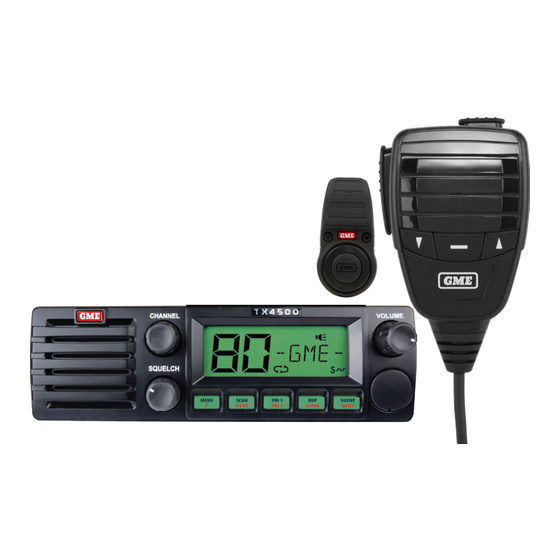
- Page 1 ARTWORK SUMMARY 53687-1 DRAWING # PART # 311189 GRA-4588 JIRA REFERENCE ECO # Online SUPPLIER MPE # TX4500SWS2 5 WATT DIN MOUNT UHF CB RADIO WITH WIRELESS PTT WARNING WARNING THIS PRODUCT CONTAINS BUTTON/COIN CELL BATTERIES INSTRUCTION MANUAL TX4500WS2 Instruction Manual...
-
Page 2: Table Of Contents
CONTENTS ACCESSORIES SUPPLIED .................. 4 INTRODUCTION ....................4 IMPORTANT INFORMATION CONCERNING UHF CB RADIO ........ 4 Possible issues ......................5 Emergency channels ....................5 TELEMETRY CHANNELS ................... 5 FEATURES ......................6 GENERAL OPERATION ..................7 Front Panel Controls .....................7 Rear Panel ......................7 LCD Panel ......................8 Microphone ......................8 Keypad Functions ....................9... - Page 3 Microphone Gain Adjustment ................58 NOISE SUPPRESSION ..................59 SPECIFICATIONS ..................... 62 W2 SPECIFICATIONS ..................64 GME WARRANTY AGAINST DEFECTS ............. 65 WARNING THIS PRODUCT CONTAINS A BUTTON BATTERY. If swallowed, a lithium button battery can cause severe or fatal injuries within 2 hours.
-
Page 4: Accessories Supplied
Mounting Hardware INTRODUCTION Your GME TX4500S 80 channel radio is Australian designed and built and is the most advanced UHF Citizen Band radio available. Combining the very latest in electronic hardware with the most up-to-date computer aided design and manufacturing techniques has resulted in a mobile radio with outstanding specifications and performance. -
Page 5: Possible Issues
The newer narrowband radios will be able to converse with all older 40 channel wideband radios on all channels 1 to 40 as well as the newer channels allocated from 41 to 80. The mixing of narrowband and wideband radios in the same spectrum can cause some possible operating issues of interference and varying levels of received volume. -
Page 6: Features
FEATURES FEATURES TRANSMIT (TX) Individually Programmable DUPLEX Function: User selectable for only those individual channels in your area that have repeaters, leaving the others free for use as extra simplex channels. RECEIVE (RX) User Selectable Wide/Narrow Receive Filter User Programmable Receive-Only Channels: Use the radio’s front panel controls to program up to 95 of your own receive-only channels (in 5 banks of 19 channels) within the 403-520 MHz frequency range. -
Page 7: General Operation
PHYSICAL PROPERTIES Overvoltage Protection: Special overvoltage detection circuitry protects the radio and warns of excessive voltage conditions by flashing the display. Dual Microphone Input Sockets: Front and rear microphone sockets to match most installation needs. Both sockets can be used independently or simultaneously. USER CONTROLS AND INTERFACE High Contrast Liquid Crystal Display: Fully detailed LCD provides a visual indication of the selected channel and all selected functions at a glance. -
Page 8: Lcd Panel
LCD PANEL Channel Display SelCall TX Quiet Busy SelCall RX Transmit SelCall/Alpha Display/ Scan Repeater Quiet CTCSS/DCS Signal Meter/Battery (Duplex) MICROPHONE Skip/Call Push To Talk Channel Down Priority Channel Up TX4500WS2 Instruction Manual... -
Page 9: Keypad Functions
KEYPAD FUNCTIONS All controls on the TX4500S front panel have multiple functions. The primary functions are labelled in black, while the secondary functions are labelled in red. To access a primary function simply press the required key. To access a secondary function, briefly press the F key followed immediately by the required key. -
Page 10: Signal Meter
Adjusting the Squelch level The TX4500S features a continuously variable Squelch control system allowing the user to set the Squelch for optimum performance. To adjust the Squelch, first rotate the Squelch control fully counter-clockwise until the background noise is heard and the indicator is displayed on the LCD. -
Page 11: Backlighting
When the time-out timer activates, the radio will beep for 5 seconds then the icon will flash continuously. Normal operation will be restored once the PTT is released. BACKLIGHTING The Liquid Crystal Display and keys are backlit for easy viewing at night. The backlight remains on while the radio is switched on. -
Page 12: Dynamic Volume Control (Dvc)
To select the desired filter, press and hold the MENU key to enter the menu, then press the MENU key repeatedly until NBFLT (Narrowband Filter) or WBFLT (Wideband Filter) is displayed. Rotate the Channel control left or right to make the desired selection. When finished, briefly press the PTT to exit from the Menu. -
Page 13: Silent Squelch Tail
Your radio incorporates a simple voice scrambler using band inversion. The scrambler is compatible with the majority of scramblers used by other manufacturers, allowing you to enjoy scrambled communications with owners of non-GME radios. Once the scrambler has been activated your transmission and reception will only be intelligible to others using the same scrambler technology. -
Page 14: Repeaters And Duplex Mode
REPEATERS AND DUPLEX MODE Duplex operation allows the radio to transmit on a different frequency to that which it receives. This allows operation through repeater stations. A repeater station consists of a linked transmitter/receiver combination installed in a prominent location. The repeater is designed to receive signals on a designated channel and retransmit them on another channel. -
Page 15: Priority Channels
Your radio allows you to enable or disable Duplex mode on individual repeater channels. In this way any repeater channels that are not being used with repeaters in your area can be used in Simplex mode for normal direct radio-to-radio communications. To Enable Duplex on a Repeater Channel 1. -
Page 16: Scanning
beep will be heard as the channel is stored. 'PRI-2' will be displayed briefly. To Recall Priority Channel 1 1. Briefly press the PRI 1 key. The radio will immediately switch to the Priority 1 channel and 'PRI-1' will be displayed briefly. To Recall Priority Channel 2 1. -
Page 17: Open Scan
The radio will temporarily remove the busy channel from the scan group for 30 seconds to allow time for the channel to become clear again. Scanning will then continue from the next channel in the sequence. After 30 seconds the skipped channel will be reinstated in the scan sequence. - Page 18 Default Working Channel in Open Scan Mode In the Open Scan mode, your default working channel is the channel your radio switches to when you press the PTT while scanning. To define your working channel simply select the required channel before you press the SCAN key. e.g. to make channel 24 your working channel, simply select channel 24 before pressing the SCAN key.
-
Page 19: Group Scan
GROUP SCAN Group Scan allows you to scan a number of channels for activity while also monitoring your Priority channel. The receiver will scan the other channels ONLY WHILE THERE ARE NO SIGNALS ON THE PRIORITY CHANNEL. If a signal appears on the priority channel it will override any signals being received on any of the other channels. -
Page 20: Additional Open/Group Scan Options
Alternately you may prefer to have two separate Group Scan modes with different Scan channels in each. Your radio can be programmed to convert the Group Scan into an Open Scan and vice versa. If this is required, please contact your GME retailer to arrange for this feature to be activated. -
Page 21: Network Scan (Net-Scan)
NETWORK SCAN (NET-SCAN) Net-Scan allows a group of radio users to maintain communications even when the band is congested. To achieve this all members of the Net-Scan group must share a common CTCSS/DCS code and a common set of scan channels. Once activated, Net-Scan’s intelligent scanning software keeps track of clear channels within your scan group. - Page 22 Programming channels into Net-Scan. All radios in your Net-Scan group must have the same channels programmed into their Net-Scan memory. Your radio’s Net-Scan memory has already been factory programmed with 43 of the available 80 channels. The remaining 37 channels, which consist of the 32 repeater input/output channels, 2 telemetry channels and 3 guard-band channels, have not been included to minimise the risk of interference to other services on these channels.
-
Page 23: Using The Priority Channel While Scanning
Using Net-Scan When a member of the group initiates a transmission their radio will automatically select a clear channel to transmit on. Other radios scanning in the same Net-Scan group will locate the transmission by identifying the group’s CTCSS/DCS code and open their Squelch allowing the transmission to be heard across the entire group. - Page 24 However, please refer to the tone set tables listed in each radio’s Instruction manual for compatibility because, although the same 50 tones are available in all GME radios, the tones used in older GME models may be listed in a different order to those in your radio. DCS Tone Set There are 104 DCS tones available (see the DCS tone chart at the rear of this manual).
- Page 25 CTCSS Label CTCSS Sub tone Frequency 5. To switch CTCSS/DCS tones Off, rotate the Channel control fully to the left until ‘CTCOF’ is displayed. To exit the menu, briefly press the PTT or wait for the menu to time-out. NOTE: The selected CTCSS/DCS tone will be used globally on any channels that have CTCSS enabled.
-
Page 26: Selective Calling
IMPORTANT: When Silent mode is enabled on a channel you should always check icon for signs of traffic on the channel before transmitting to ensure you do not accidentally transmit over the top of another user. Alternatively, you can enable Busy Lockout in the Configuration menu which will automatically prevent your radio from transmitting if the channel is already in use. -
Page 27: Using Selcall
SelCall Ident Labels When storing SelCall Idents, you can add labels to each one to make it easier to identify whose Ident you are recalling. In addition, if an incoming SelCall matches one of your stored Idents, the label can be displayed instead of the Ident. To add or display labels, your radio must be in the ALPHA mode. - Page 28 Note: If the call is not sent within 10 seconds of entering the last Ident digit the Call function will time-out and the radio will return to normal mode. To exit the mode without sending the SelCall, briefly press the CALL button. Call Acknowledge If your SelCall transmission is successful, the radio you called should respond with an ‘acknowledge’...
- Page 29 Recalling SelCall Idents 1. Briefly press the CALL button. is displayed along with the last sent or received SelCall Ident. 2. Rotate the Channel control to select the required Ident memory in locations ‘C0’ to ‘C9’. 3. Press and hold the CALL button to send the Ident. Naming your SelCall Idents Your radio allows you to label each SelCall Ident using a 5 character name to make it easier to identify callers.
- Page 30 Repeat steps 2 to 8 to add ALPHA labels to any other SelCall Idents stored in memory. The following characters are available; Letters A B C D E F G H I J K L M N O P Q R S T U V W X Y Z Numbers 0 1 2 3 4 5 6 7 8 9...
-
Page 31: Quiet Mode
QUIET MODE The Quiet Mode mutes the receiver to prevent incoming signals from being heard in the speaker until your SelCall Ident is received. In this way you can monitor a busy channel for personal calls without being disturbed by unwanted signals. If your SelCall Ident is received, the Quiet mode is cancelled and all incoming signals are heard in the speaker. - Page 32 • If your SelCall Ident is received on any channel - Open or QUIET - the Quiet mode will be cancelled and the alarm will beep to alert you to the call. In addition, the caller’s Ident or ALPHA label will be displayed. All channels will now be open for normal transmission and reception.
-
Page 33: Group Calling
GROUP CALLING The SelCall system includes a Group call function which allows you to call up to 1000 radios simultaneously. This can be useful in an emergency situation where you may need to transmit a message to a large number of radios in your group. By default, your radio is factory-set to allow up to 10 radios to be called at once. -
Page 34: Receive-Only Channels
3. Rotate the Channel control to select ‘A’ in the flashing digit position. This is the special code that will create the Group Call. 4. Briefly press the Channel control again to select the next digit position. 5. Continue entering the other 4 digits as required. The SelCall number is now ready to send. - Page 35 Frequency programming and channel bank selections are accessed through the configuration menu. Selecting Channel Banks Before programming or recalling channels you should select the required channel bank. The 5 channel banks can be enabled through the menu either as individual banks of 19 channels (RX-A, RX-B, RX-C, RX-D or RX-E) or as a combined group of 95 channels (RXA-E).
-
Page 36: Combined Channel Banks Rxa-E
COMBINED CHANNEL BANKS RXA-E RX-A RX-B RX-C RX-D RX-E To Select a Channel Bank 1. Press and hold the Menu key. A high beep will be heard and the radio will enter the configuration menu. 2. Briefly press the Menu key repeatedly until the RX- channel bank option is displayed. - Page 37 Programming RX-only Channel Frequencies RX-only channels are switched off by default. To program RX-only channels you will need to activate the channel editor which will then allow access to channels 81-99 in the currently selected channel bank. RX-only channels can be programmed with frequencies in the range 403 –...
- Page 38 2. Press and hold the Menu key until the radio beeps. ‘–OFF-’ will flash. You now have 6 seconds to begin programming otherwise the menu will time-out. 3. Rotate the Channel control to the right to begin selecting your desired frequency starting at 403 MHz.
- Page 39 To Close the Channel Editor Switch the radio Off then On again to close the channel editor and restore normal operation. Your programmed frequencies will now be accessible from the Channel control above CH80. Remember, if you have stored channels into different channel banks, you will need to select the appropriate channel bank to access them.
-
Page 40: Configuration Menu
To Display the Channel’s ALPHA Label Briefly press F then ALPHA. ‘ALPHA’ will appear briefly then the channel’s Alpha label will be displayed to the left of the channel number. If the Alpha label is blank, then an Alpha label has not yet been set for this channel. Use the following steps to enter your preferred Alpha label. - Page 41 The following settings are available. Menu Option RX-only RX-only Frequency, Frequency /Label Alpha Label editing CTCOF (CTCSS OFF) CTCSS CTC01 to CTC50 (CTCSS Tones) DT001 to DT104 (DCS Tones) NS-OF (Netscan OFF) Network Scan NS-01 to NS-50 (Netscan On Using CTCSS) NS001 to NS104 (Netscan On Using DCS) ENCOF (Scrambler OFF) Voice Scrambler...
- Page 42 Frequency/ Alpha Label (only available on receive-only channels) Allows editing of the channel frequency or Alpha label of the selected receive-only channel. Frequency 458.325 MHz Alpha label “FIRE 1” CTCSS/ DCS Tone Selection Enables and selects CTCSS or DCS tones. To switch CTCSS or DCS tones off rotate the Channel control fully to the left until ‘CTCOF’...
- Page 43 Silent Squelch Tail ON Silent Squelch Tail OFF Beep Tone Level Adjusts the volume level of the beep tones associated with key presses. Beep level 0 Beep level 9 Frequency Step Selection (only available on receive-only channels) Sets the frequency spacing of receive-only channels to 12.5 kHz or 25 kHz (default). 25 kHz steps 12.5 kHz steps Note: This option does not affect the standard 80 CB channel spacing.
- Page 44 • S-LIN: Shows received signal strengths with extended resolution from 0 (no signal) to approximately 63 (very strong signal). A change of 1 digit in this mode corresponds to around a 10% change in signal strength. • BATT: Displays the battery voltage. •...
-
Page 45: Installation
INSTALLATION Your TX4500S is supplied with a DIN mounting bracket for mounting into a standard DIN sized cavity in the vehicle’s console or dashboard. Before installing the radio, ensure the DC cable and antenna have been installed correctly (as described on following pages) and the connectors are accessible through the DIN cavity. -
Page 46: Dc Power Connection
4. Secure the radio using the four 8mm bolts supplied. Note: Bolts should not extend more than 6mm inside the radio otherwise they may come into contact with the internal components. 5. Feed the antenna connector and DC lead through the DIN slot in the dashboard and connect these to the matching sockets on the radio. -
Page 47: Microphone
Radio remains ON when ignition switch is OFF Fuse To Radio BLACK Ingnition Switch Chassis Car battery Radio turns ON and OFF with ignition switch Fuse To Radio BLACK Ingnition Switch Chassis Car battery The radio should now switch ON and OFF automatically with the vehicle’s ignition switch. - Page 48 Position the microphone plug so the plastic tab faces upwards then press the plug into the socket until it ‘clicks’. VOLUME Plastic tab SILEN T ALPH A QUIE T Gently press the rubber strain relief grommet into the hole surrounding the socket so that the slot around the grommet fits neatly inside the lip inside the hole.
-
Page 49: Antenna Installation
GME have a huge range of suitable 477 MHz antennas to suit most installations and applications. We recommend you contact your local retailer for advice. -
Page 50: W2 Installation
W2 INSTALLATION WIRELESS PTT RANGE The W2 wireless PTT button has a maximum line-of-sight range of approximately 5-7 metres depending on the installation. Please be aware of the range performance when planning your installation. WIRELESS PTT MOUNTING STEERING WHEEL MOUNT The steering wheel mount clamps onto the steering wheel in a position where the W2 can be easily reached without distraction while driving. -
Page 51: W2 Steering Wheel Clamp Mount
W2 STEERING WHEEL CLAMP MOUNT Use a 2.5mm Hex key to loosen the two bolts on Steering Wheel Clamp Mount without removing it. If the steering wheel has a small diameter OR has soft grips then an additional 2.0mm spacer may be required. Slide W2 onto steering wheel and adjust for preferred location/angle. -
Page 52: W2 Dash Mount
Maximum Diameter 35.0mm Minimum Diameter 27.6mm W2 DASH MOUNT Remove protective film from the adhesive on the Hook Fastener Patch (the one with the hole) and affix the patch to the bottom of the PTT Button. Ensure that the slots on the PTT Button are unobstructed. -
Page 53: Battery Change
BATTERY CHANGE Remove Clamp Mount Cap. Remove PTT Button. For Flat Head screwdriver (max 1.2 x 6.5mm) For 10 cent coin ONLY Use a 10c coin OR a Flat head screw driver (max size 1.2 x 6.5mm). To unscrew PTT Button lid do not use other tools as it might damage the slots. - Page 54 Remove and Replace 3V CR2032 coin cell battery. Place PCB with new coin cell into main housing. Use the orientation notch to align PCB in correct position. Note: These steps are important as it will ensure the unit is IP67 rated/waterproof and that the switch has the correct tactile feel and engagement.
-
Page 55: Pairing
PAIRING Your TX4500WS2 will be paired with the W2 wireless PTT. No initial pairing is required. If the battery is removed from the W2 then the PTT may need to be paired to the radio. The pairing process uses a secure internal code to link your W2 exclusively with your radio. -
Page 56: Wiring
microphone and use it for both handheld and hands-free operation. To select the hands-free microphone input; Press and Hold the Menu key until the radio beeps. The radio will enter the Menu mode. Press the Menu key repeatedly until ‘WMIC1’ or ‘WMIC2’ is displayed. Rotate the Channel selector or press the keys to toggle between ‘WMIC1’... -
Page 57: Installing The Remote Microphone
INSTALLING THE REMOTE MICROPHONE The external remote microphone should be installed in a location close to your driving position that will allow it to easily pick up your voice while driving. Suggested areas are the driver’s side door pillar, sun visor or roof mounted centre console. Once installed, run the cable to your radio and plug it into either the front or the rear microphone socket of the radio. -
Page 58: Microphone Gain Adjustment
MICROPHONE GAIN ADJUSTMENT The microphone gain controls the sensitivity of the selected hands-free microphone when operating in hands-free mode. Since the mounting position of the hands-free microphone will vary between installations, the gain control allows you to adjust the microphone sensitivity to ensure your voice is transmitted clearly. When the gain has been adjusted correctly, your hands-free voice level, when heard on a receiving radio, should sound similar to that when using your hand microphone the conventional way. -
Page 59: Noise Suppression
When the required gain has been set, press and hold Menu (or wait for the Menu function to time-out) to store your setting and exit the Menu. Repeat from step 1 until your hands-free voice level is similar to talking into your hand microphone. - Page 60 CTCSS TONE FREQUENCY CHART Frequency Frequency Frequency Frequency 67.0 107.2 167.9 159.8 71.9 110.9 173.8 165.5 74.4 114.8 179.9 171.3 77.0 118.8 186.2 177.3 79.7 123.0 192.8 183.5 82.5 127.3 203.5 189.9 85.4 131.8 210.7 196.6 88.5 136.5 218.1 199.5 91.5 141.3 225.7...
- Page 61 UHF CB OPERATING FREQUENCIES Frequency Frequency Frequency Frequency (MHz) (MHz) (MHz) (MHz) 476.425 476.925 476.4375 476.9375 476.450 476.950 476.4625 476.9625 476.475 476.975 476.4875 476.9875 476.500 477.000 476.5125 477.0125 476.525 477.025 476.5375 477.0375 476.550 477.050 476.5625 477.0625 476.575 477.075 476.5875 477.0875 476.600 477.100 476.6125...
-
Page 62: Specifications
SPECIFICATIONS Electrical Meets AS/NZS 4365 for radio communications equipment in the Compliant Specification: UHF citizen and personal radio service. Frequency Range TX: 476.425 – 477.4125 MHz Number of Channels: 80 UHF CB Channel Spacing: 12.5 kHz Operation Mode: Simplex or half duplex with repeater talk around. Scanning Speed: 25 ms per channel (40 channels per second). - Page 63 SPECIFICATIONS Transmitter Transmit Frequency Response: +6 dB per octave 300 Hz to 3 kHz + 1-3 dB Demodulated Audio > 45 dB unweighted Signal to Noise: Current Consumption: 1.7 amps with 50 Ohms termination. Receiver Intermediate Frequencies: 38.85 MHz, 450 kHz -122 dBm for 12 dB Sensitivity: SINAD unweighted...
-
Page 64: W2 Specifications
W2 SPECIFICATIONS Electrical Compliant specification: Meets AS/NZS 4268:2008 for short range devices Frequency range TX: 2.4 GHz Operating temperature: -10°C to 60°C Current consumption: 2 uA on standby, 12 mA on transmit RF output: 4 dBm Battery type: CR2025 Mechanical Dimensions: (Wireless PTT 80mm (L) X 40mm (W) X 38mm (H) button with clamp) -
Page 65: Gme Warranty Against Defects
GME WARRANTY AGAINST DEFECTS This warranty against defects is given by GME Pty Ltd ACN 000 346 814 (We, us, our or GME). Our contact details are set out in clause 2.7. Consumer guarantees 1.1 Our goods come with guarantees that cannot be excluded under the Australian Consumer Law. - Page 66 (f)) goods where the serial number has been removed or made illegal. Warranty period 4.1 We provide the following warranty on GME and Kingray products. No repair or replacement during the warranty period will renew or extend the warranty period past the period from original date of purchase.
Need help?
Do you have a question about the TX4500SWS2 and is the answer not in the manual?
Questions and answers