
Related Manuals for Virone MAILO VDP-70


Summary of Contents for Virone MAILO VDP-70
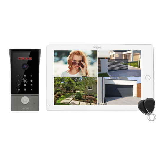
- Page 1 Operating and installation instructions Video doorphone set MAILO VDP-70 STOP! Be sure to read the instruction manual before installation! Damage resulting from incorrect connection ARE NOT SUBJECT TO REPAIR UNDER WARRANTY!
-
Page 2: Table Of Contents
TABLE OF CONTENTS 1. SAFETY INSTRUCTIONS.................................... 3 2. CHARACTERISTICS OF THE SET ................................3 3. TECHNICAL DATA ..................................... 4 MONITOR ..........................................4 OUTDOOR UNIT ........................................4 4. SET CONSTRUCTION ....................................5 MONITOR ..........................................5 OUTDOOR UNIT ........................................5 5. INSTALLATION ......................................5 MONITOR INSTALLATION .................................... -
Page 3: Safety Instructions
Sp. z o.o. holds no responsibility for the results of non-compliance with the provisions of the present Manual Orno Logistic Sp. z o.o. reserves the right to make changes to the Manual - the latest version of the Manual can be downloaded from www.virone.pl. -
Page 4: Technical Data
3. TECHNICAL DATA TYPE OF THE DEVICE: single-family INSTALLATION METHOD: 4-wire COMMUNICATION SYSTEM: wireless - monitor and WiFi router, wired - monitor and outdoor unit WLAN FREQUENCY RANGE: 2.400-2.483,5 MHz (IEEE 8111b/g/n/ac) MAXIMUM TRANSMITTING POWER: <100mW EIRP MONITOR SCREEN SIZE: 10”... -
Page 5: Set Construction
4. SET CONSTRUCTION fig. 1 Construction of the monitor and outdoor unit. MONITOR OUTDOOR UNIT 1. Touchscreen 1. Loudspeaker 2. Main button 2. Camera lens 3. Microphone 3. Call button 4. On/Off switch 4. Night-time lighting 5. MicroSD card slot 5. -
Page 6: Outdoor Unit Installation
OUTDOOR UNIT INSTALLATION fig. 3 Outdoor unit placement Do not install the device close to sources of strong radiation, e.g. hoists and other drive systems powered by alternating current. Installation should be carried out by a qualified technician only. Do not install the outdoor unit in a location with harsh weather conditions, e.g.: heavy rainfall, high temperature, high humidity, high dust, presence of corrosive chemicals. -
Page 7: Wiring Diagrams
6. WIRING DIAGRAMS The electric strike/alarm/camera is not included in the set. You must purchase an electric strike that best suits the requirements of the set (12VDC maks. 500mA). In the standard model, the system works with strikers that open with a NO contact. This means that in normal operation, the dry contact is open, so the striker is permanently closed. - Page 8 fig. 7 Wiring diagram It is forbidden to make connections to live equipment! Failure to adhere to this recommendation may result in permanent damage to the device and loss of health.
- Page 9 fig. 8 Detailed wiring diagram The set does not include an electric door strike and automatic gate control unit!
- Page 10 fig. 9 Electric strike and exit button wiring diagram electromagnetic jumper fig. 10 Electromagnetic jumper and exit button wiring diagram fig. 11 Second electromagnetic jumper and exit button wiring diagram fig. 12 Second electric strike and exit button wiring diagram...
-
Page 11: Monitor Operation
7. MONITOR OPERATION MAIN MENU In standby mode, touch the screen to display the Main Menu. INTERNAL CALL Users can connect to other (connected) monitors. The last icon calls up a call to all additional monitors, which can be answered on any monitor. -
Page 12: Call Transfer To Other Monitors
CALL TRANSFER TO OTHER MONITORS The internal communication function requires the connection of at least two indoor monitors and one outdoor unit. MONITORING FROM OUTDOOR UNIT The main menu displays 4 icons: Door1, Door2, Camera1, Camera2. Select one of these to view a preview of your surroundings. - Page 13 1. The monitoring time is 120 seconds. After this time, the monitor automatically returns to standby mode. 2. During the preview from the outdoor unit, only the image is visible, no sounds from the camera environment can be heard. No ambient sounds from the monitor can also be heard in front of the outdoor unit. 3.
-
Page 14: Picture Parameter Setting
PICTURE PARAMETER SETTING During an incoming call from an outdoor unit, the following settings can be made: call volume, image brightness, contrast and color saturation. Touch the icons on the right/left to increase/decrease the value of a parameter accordingly. Call volume Value in the range 0-10. -
Page 15: Motion Detection
MOTION DETECTION 1. In standby mode, touch the screen, select Settings > Outdoor Unit Settings/Camera Settings > Select Device > Motion Detection. 2. When the Motion Detection option is enabled, the camera image will be displayed on the monitor when motion is detected in the detection area. -
Page 16: Event Recording
EVENT RECORDING Automatic camera view snapshot or video recording when any outdoor unit calls, Manually camera view snapshot or video recording when any outdoor unit calls. Call record If the answering machine function is activated, the user can listen to the recorded messages. Message record Automatic camera view snapshot or video recording when motion is detected by any outdoor unit,... -
Page 17: Gate Opening
Automatic camera view snapshot or video recording when an alarm is triggered, Manually camera view snapshot or video recording when an alarm is triggered. Alarm info Saved recordings for preset time periods. GATE OPENING Press the gate icon (Lock) on the monitor to open the gate. -
Page 18: Working Modes
8. WORKING MODES STANDBY MODE In standby mode, the menu options are displayed in two different ways, as clock mode and digital frame mode. Clock mode Includes display of current date and time and shortcut buttons: interface switch, call record, message record, motion detection, alarm info and DVR. -
Page 19: Settings
Not at home – the possibility for the visitor to leave a message immediately after making the connection. Sleep mode – muted ringtone and notification sound. 9. SETTINGS SYSTEM SETTINGS Indicates the device ID (range 1 to 6). The value 1 is the designation of the main monitor, Device_id while values from 2 to 6 indicate additional monitors. -
Page 20: Outdoor Unit Settings
Idle mode Selectable clock view or blank screen. Ringback Enable or disable incoming call sound. Indicates the length of the signal to the gate automation (range 1-10 seconds). Default Indoor unlock delay setting is 2 seconds. OUTDOOR UNIT SETTINGS After touching on the door station settings, the settings for Outdoor unit 1 and Outdoor unit 2 are displayed. Enable switch Enable or disable the outdoor unit for Door1 or Door2 respectively. -
Page 21: Camera Settings
Ring setting The user can set the schedule for the corresponding ringtones, the duration of the ringer, select the type of ringer, the melody and set the volume. A: The default settings are the following time periods: Ring 1 – 6:00-12:00, Ring 2 – 12:00- 18:00, Ring 3 –... -
Page 22: Network Settings
Alarm ring Choice of 2 ringtones/melodies or alarm off. The default setting is 1. Enable or disable motion detection. Choice of 3 modes: low, medium and high, which Motion detection indicate the sensitivity of detection. Motion detection Indicates the recording time when motion is detected (range 10-300 seconds). Default duration setting is 20 seconds. - Page 23 3.2. In the app on your phone, click Add device and then click the Scan icon located in the upper right corner. Scan the QR code displayed on the monitor to start the process of pairing the device with your phone. 3.3.
- Page 24 Pairing the device with the internet - cable code: 4.1. Connect the monitor to a Wi-Fi router using a network cable, then connect your smartphone to a Wi-Fi network with the same name. 4.2. On the monitor, go to Settings>Network and then select Net pairing Mode>Cable and press Return button. The device will prompt you to reboot the system, press Yes.
-
Page 25: Photo Frame Settings
User invitation 1. Select the Me tab on the bottom bar of the app, then enter Home management>My Home. Here, give the family a name (e.g. the Smiths). 2. Select Add members. On the app screen, options of sharing the invitation code will appear (e.g. text message). Invited users can add their device by entering the invitation code in Home management>Join a home - once the app is installed. -
Page 26: Senior Settings
SENIOR SETTINGS Factory setting Press OK to restore factory settings. Press OK to update. If the update is successful, the message ‘Success’ will be displayed on the monitor screen and the device will restart. If an error occurs, an error message will be Software update displayed. -
Page 27: Outdoor Unit Operation
10. OUTDOOR UNIT OPERATION Factory settings: Administrator password: 999999 Access password (Door 1): 123456 Access password (Door 2): 456789 Access methods: proximity card/tag and PIN code Electric door strike release time: 2 seconds Failure mode is deactivated at the factory. Quick programming guide * administrator password # Entry into programming mode... - Page 28 1. Resetting to factory settings Disconnect power from the outdoor unit, then press and hold the exit button while restoring power. Release the button after hearing three signals. The factory settings have been restored. Note: restoring factory settings does not delete all stored data. 2.
- Page 29 10. Edit safety functions Deactivation of alarm and keypad / proximity reader lock 5 (keypad backlighting flashes faster) + 00 + # (two signals, keypad backlighting flashes slowly) Activation of keypad / proximity reader lock 5 (keypad backlighting flashes faster) + 01 + # (two signals, keypad backlighting flashes slowly) Activation of alarm and keypad / proximity reader lock 5 (keypad backlighting flashes faster) + 02 + # (two signals, keypad backlighting flashes slowly) Lockout mode means that if an invalid card/tag is repeatedly approached within 5 minutes or 10 incorrect passwords...
-
Page 30: Alarm Mode
Simplified declaration of conformity Orno-Logistic Sp. z o.o. declares that the type of radio device VDP-70 Video doorphone set Mailo is compliant with the Directive 2014/53/EU. The full text of the EU declaration of conformity is available at the following web address: www.virone.pl.
Need help?
Do you have a question about the MAILO VDP-70 and is the answer not in the manual?
Questions and answers