
Related Manuals for Virone ACERO VDP-71


Summary of Contents for Virone ACERO VDP-71
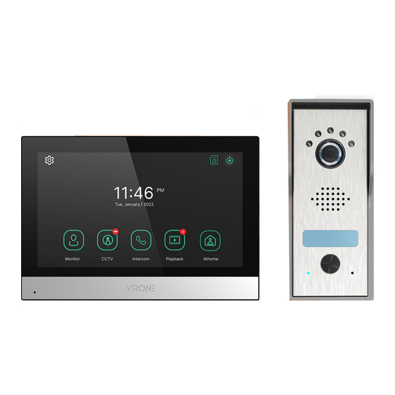
- Page 1 Operating and installation instructions Video doorphone set ACERO VDP-71 STOP! Be sure to read the instruction manual before installation! Damage resulting from incorrect connection ARE NOT SUBJECT TO REPAIR UNDER WARRANTY!
-
Page 2: Table Of Contents
TABLE OF CONTENTS 1. SAFETY INSTRUCTIONS.................................... 2 2. CHARACTERISTICS OF THE SET ................................3 3. TECHNICAL DATA ..................................... 3 MONITOR ..........................................3 OUTDOOR UNIT ........................................4 4. SET CONSTRUCTION ....................................4 MONITOR ..........................................4 OUTDOOR UNIT ........................................4 5. INSTALLATION ......................................5 MONITOR INSTALLATION .................................... -
Page 3: Characteristics Of The Set
2. CHARACTERISTICS OF THE SET Videodoorphone is designed for installation in 1-family buildings. Functions: - simultaneous view and hold of a conversation with a person in front of an entrance; - direct control of an electric door strike; - gate control; - stepless adjustment of monitor parameters (image brightness, colour saturation, volume) - bright white LED lighting allowing night vision;... -
Page 4: Outdoor Unit
OUTDOOR UNIT SENSOR TYPE: CMOS 1/2.9” RESOLUTION: 1080P FHD VIEWING ANGLE (VERTICAL/HORIZONTAL): 46° / 93° NIGHT LIGHTING: white LED diodes NUMBER OF DIODES: NIGHT VISION RANGE: ≤1m MOTION SENSOR: INGRESS PROTECTION: IP44 POWER SUPPLY: 15V DC from monitor POWER CONSUMPTION: standby <0,5W, work <3W WORKING TEMPERATURE: -20°C ~ +50°C... -
Page 5: Installation
5. INSTALLATION MONITOR INSTALLATION fig. 2 Monitor installation 1. Drill holes in the wall and insert silicone dowels into them. 2. Screw the monitor mounting bracket to the wall with screws. 3. Connect the wires to the monitor and hang it on the mounting bracket. 4. -
Page 6: Wiring Diagrams
fig. 4 Outdoor unit with camera installation Drill holes in the wall and insert the silicone dowels. Pull through the wires and screw the rainshield into place using screws. 2. Remove the screws located on the top and bottom of the outdoor unit and pull off the metal cover. Write down your name on the nameplate and tighten the cover back to the panel. - Page 7 fig. 6 Wiring diagram The set does not include an electric door strike and automatic gate control unit! The video doorphone cables should not be routed in one cable with the cables of other installations such as bell, alarm, etc. Any power and telecommunication cables emitting strong magnetic fields (e.g.
-
Page 8: Set Operation
7. SET OPERATION MAIN MENU Monitor Outdoor unit camera view. CCTV CCTV camera view. Intercom Intercom function (available with additional monitors connected). Playback Display a list of recorded photos and videos. Three possible settings: at home/ away/ do not disturb. At home: call and conversation available, Operating mode Away: option of leaving a message by a visitor,... -
Page 9: Monitoring
MONITORING Go back to the previous page. Door 1: indicates the active camera from which the image is displayed on the screen. Recording status icons: Recording format: Photo/Video (in motion detection mode) Recording mode: MANUAL/AUTO SD card status: Inserted/Memory full Change the preview to the second external panel. -
Page 10: Call Volume And Image Adjustment
CALL VOLUME AND IMAGE ADJUSTMENT During monitoring or a call, press any area of the image to enter the call volume/ image brightness/ image contrast/ colour saturation adjustment window. CONNECTION 1. When the Call button on the outdoor unit is pressed, the monitor beeps and the image from the external camera is displayed on the screen. -
Page 11: Intercom
Indicates the active CCTV camera from which the image is displayed on the screen. Current time and date. Recording status icon (shows current format and recording mode). Possible change of view to image from CCTV camera 2 (if installed). Video recording: press to start recording the view from the CCTV camera. During recording, the remaining time will be displayed in the upper right corner. -
Page 12: Playback
11. PLAYBACK Current page/number of all pages. Go to next page/go back to previous page. File information. Image Video New file Alarm recording: file recorded when an alarm occurs. If "Auto Recording" is selected in the security menu, the CCTV camera image is recorded for 10 seconds in the case of an emergency. -
Page 13: Video
VIDEO Source/file number. Go to next/go back to previous video. Play video - press to play the current video file. During playback, the icon changes into a pause button. Delete file. Date and time. Video file duration: the remaining time is displayed. Note: After inserting the SD memory card into the device, wait for a while for the files on the card to load. - Page 14 Motion detection Activate the option to set motion detection for the previously set camera. The motion detection functions are as follows: Enable motion detection: on/off. Camera selection: select camera for monitoring the environment (door 1/2, CCTV camera 1/2 - if installed). Recording format: select image/video.
-
Page 15: Volume
VOLUME An individual ringtone can be set for each outdoor unit (6 melodies to choose). Door 1/Door 2 Option to set 3 different ringing schedules for 3 different time intervals (adjust the time interval for a given ring, the ringing time, the ringing mode and its melody and volume). Touch tone On/off. -
Page 16: Storage
STORAGE Format SD card Select to format the SD memory card. The process may take about 1 minute. Files deletion Select the photos or videos you wish to delete. SD card capacity Displays the free and total capacity of the SD card. Flash capacity Displays the free and total memory capacity of the monitor. -
Page 17: Display
DISPLAY Brightness/contrast/colour saturation can be adjusted (settings apply to the image displayed Screen from external camera). The settings can be adjusted from 0-20. Return to default settings by adjustment pressing the icon in the upper right corner. Enter standby Choose from different standyby modes. mode LCD off (after 30 seconds): the screen switches off after 30 seconds if no action was performed during this time. - Page 18 Night mode: choose to dimm the screen brightness in a given time interval. List of display: select the features you wish to display on the monitor screen together with the screen carousel function. Screen carousel time: select the background you wish to display together with the screen carousel function.
-
Page 19: Etc
Set the language of the menu, choose from: Polish, English, German, French, Portuguese, Arabic, Language Turkish, Korean, Russian, Spanish, Chinese. Extension If multiple monitors are connected, select a different ID number for each monitor. ID setting Gate/Door Configure the gate/door opening time. unlock time Security password Default setting: 1234. -
Page 20: Sd Card
After setting the alarm 6: Indicates which detectors have the security alarm function activated. 7: Deactivate the alarm function: press the Stop button and enter the 4-digit security password (factory setting 1234). When an emergency alarm is triggered, the alarm siren goes off for minutes. -
Page 21: Troubleshooting
14. TROUBLESHOOTING 1. No audio/video, no indicator light a) no supply voltage, b) damaged or incorrectly connected connecting cable, check your installation for technical requirements, c) check that the installation is not exposed to water, moisture etc., d) check that the camera lens is not obstructed by an object that prevents proper view. 2.
Need help?
Do you have a question about the ACERO VDP-71 and is the answer not in the manual?
Questions and answers