KNF N86 DC-B Operating And Installation Instruction
Diaphragm pump
Hide thumbs
Also See for N86 DC-B:
Table of Contents
Advertisement
Quick Links
Advertisement
Table of Contents

Related Manuals for KNF N86 DC-B


Summary of Contents for KNF N86 DC-B
- Page 1 KNF 346356-346370 07/24 N86_DC-B TRANSLATION OF ORIGINAL OPERATING AND INSTALLATION INSTRUCTION ENGLISH DIAPHRAGM PUMP Notice! Before operating the pump and accessories, read and observe the operat- ing and installation instructions as well as the safety information!
-
Page 2: Table Of Contents
Contents 1 About this document ................ 3 1.1 Using the operating and installation instructions...... 3 1.2 Exclusion of liability............... 3 1.3 Symbols and markings.............. 4 2 Safety .................... 6 2.1 Personnel and target group ............ 6 2.2 Responsibility of the operator ............ 7 2.3 Working in a safety conscious manner ......... -
Page 3: About This Document
The manufacturer assumes no liability for damages and mal- functions resulting from impermissible spare parts and acces- sories. Translation of Original Operating and Installation Instruction, KNF 346356-346370 07/24... -
Page 4: Symbols And Markings
CAUTION warns of a possibly Minor injury or dangerous situation damage is possi- ble. NOTICE Warns of possible Damage is possi- damage ble. Tab.1: Danger levels Translation of Original Operating and Installation Instruction, KNF 346356-346370 07/24... - Page 5 General warning symbol Warning of hot surface Warning of electrical voltage Warning of poisonous substances Warning of hand injuries through crushing Observe the operating instructions General mandatory sign Tab.2: Explanation of pictograms Translation of Original Operating and Installation Instruction, KNF 346356-346370 07/24...
-
Page 6: Safety
Tab.3: Target group Who-does-what Lifecycle phase User Specialized per- matrix sonnel Transport Mounting Connection Commissioning Operation Servicing Troubleshooting Disposal Tab.4: Who-does-what matrix Translation of Original Operating and Installation Instruction, KNF 346356-346370 07/24... -
Page 7: Responsibility Of The Operator
Ensure that the pump installation is EMC compliant such that no hazardous situations can occur. Translation of Original Operating and Installation Instruction, KNF 346356-346370 07/24... -
Page 8: Operating Conditions
Make sure that a dangerous situation cannot arise as a result. When pumping hazardous media, observe the safety regula- tions for the handling of said media. Translation of Original Operating and Installation Instruction, KNF 346356-346370 07/24... -
Page 9: Use
2.6.2 Foreseeable misuse The pumps must not be operated in explosive atmospheres. The pumps are not suitable for transferring the following: § Dusts § Liquids § Aerosols § Biological and microbiological substances Translation of Original Operating and Installation Instruction, KNF 346356-346370 07/24... -
Page 10: Directives And Standards
Standards The following standards apply: § EN IEC 61000-6-2 § EN IEC 61000-6-3 § EN IEC 55014-1/2 § EN IEC 63000 The protective goals of the following directive(s) are achieved: Translation of Original Operating and Installation Instruction, KNF 346356-346370 07/24... -
Page 11: Customer Service And Repair
Alternatively, KNF products (old devices) may also be returned to KNF for a fee (see chapter 11 Re- turns [} 56]). Translation of Original Operating and Installation Instruction, KNF 346356-346370... -
Page 12: Technical Data
[mbar abs.] Flow rate at atm. pressure [l/min]** Tab.6: *bar rel relative to 1000 hPa **Liters in the standard state (based on ISO 8778 and ISO 21360-1/2) (1000 hPa, 20°C) Translation of Original Operating and Installation Instruction, KNF 346356-346370 07/24... - Page 13 1.7 – 4.2 7.5 – 10.0 pressure [l/min]** (.29 version) Tab.8: *bar rel relative to 1000 hPa **Liters in the standard state (based on ISO 8778 and ISO 21360-1/2) (1000 hPa, 20°C) Translation of Original Operating and Installation Instruction, KNF 346356-346370 07/24...
- Page 14 Motor protection class (DIN IP 30 EN 60529 / IEC 60529) Tab.10: Electrical data Weight Pump type Value [kg] N86_DC-B 0.58 N86.3_DC-B N86.1.2_DC-B 0.67 N86.0_DC-B 0.65 Tab.11: Weight Translation of Original Operating and Installation Instruction, KNF 346356-346370 07/24...
- Page 15 80% for temperatures to air humidity of the environ- 31°C, decreasing linearly to ment 50% at 40°C (non-condens- ing). Maximum installation altitude 2000 [m above sea level] Tab.12: Other parameters Translation of Original Operating and Installation Instruction, KNF 346356-346370 07/24...
-
Page 16: Product Description
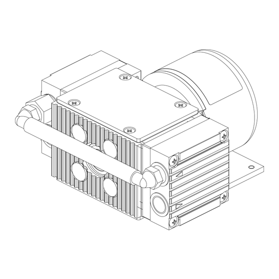
Product description Diaphragm pump N86_DC-B 4 Product description Design 1 Outlet (pres- sure side) 2 Inlet (suction side) 3 Electrical con- nection 4 Motor Fig.1: Design N86.29_DC-B Translation of Original Operating and Installation Instruction, KNF 346356-346370 07/24... - Page 17 3 Electrical con- nection 4 Motor 5 Connection Fig.2: Design N86.3.29_DC-B 1 Outlet (pres- sure side) 2 Inlet (suction side) 3 Electrical con- nection 4 Motor 5 Connection Fig.3: Design N86.1.2.29_DC-B Translation of Original Operating and Installation Instruction, KNF 346356-346370 07/24...
- Page 18 Product description Diaphragm pump N86_DC-B 1 Outlet (pres- sure side) 2 Inlet (suction side) 3 Electrical con- nection 4 Motor Fig.4: Design N86.0.29_DC-B Translation of Original Operating and Installation Instruction, KNF 346356-346370 07/24...
- Page 19 (2). In the upwards stroke, the diaphragm presses the medium out of the pump head via the outlet valve (1). The transfer chamber (3) is separated from the pump drive by the di- aphragm. Translation of Original Operating and Installation Instruction, KNF 346356-346370 07/24...
-
Page 20: Transport
There is a risk of injury from cutting on the sharp edges when grabbing cor- CAUTION ners or when opening the packaging. à Where appropriate, wear suitable personal protective equipment (e.g., safety shoes, safety gloves). Translation of Original Operating and Installation Instruction, KNF 346356-346370 07/24... - Page 21 Permissible humidity (non- 30 to 85 condensing) [%] Tab.13: Transport parameters and storage parameters Prior to commissioning, make sure that the pump has reached the ambient temperature (3 Technical data [} 12]). NOTICE Translation of Original Operating and Installation Instruction, KNF 346356-346370 07/24...
-
Page 22: Installation And Connection
Store the pump at the installation location to allow it to adapt to the ambient temperature before installation (con- densation must not be allowed to form). à Mounting dimen- For mounting dimensions, see the following figures: sions Translation of Original Operating and Installation Instruction, KNF 346356-346370 07/24... - Page 23 Installation and connection Diaphragm pump N86_DC-B Fig.6: Mounting dimensions N86_DC-B Translation of Original Operating and Installation Instruction, KNF 346356-346370 07/24...
- Page 24 Installation and connection Diaphragm pump N86_DC-B Fig.7: Mounting dimensions N86.29_DC-B Translation of Original Operating and Installation Instruction, KNF 346356-346370 07/24...
- Page 25 Installation and connection Diaphragm pump N86_DC-B Fig.8: Mounting dimensions N86.3_DC-B Translation of Original Operating and Installation Instruction, KNF 346356-346370 07/24...
- Page 26 Installation and connection Diaphragm pump N86_DC-B Fig.9: Mounting dimensions N86.3.29_DC-B Translation of Original Operating and Installation Instruction, KNF 346356-346370 07/24...
- Page 27 Installation and connection Diaphragm pump N86_DC-B Fig.10: Mounting dimensions N86.1.2_DC-B Translation of Original Operating and Installation Instruction, KNF 346356-346370 07/24...
- Page 28 Installation and connection Diaphragm pump N86_DC-B Fig.11: Mounting dimensions N86.1.2.29_DC-B Translation of Original Operating and Installation Instruction, KNF 346356-346370 07/24...
- Page 29 Installation and connection Diaphragm pump N86_DC-B Fig.12: Mounting dimensions N86.0_DC-B Translation of Original Operating and Installation Instruction, KNF 346356-346370 07/24...
- Page 30 (head, motor). à Installation loca- Make sure that the installation location is dry and that the tion pump is protected from rain, spray water, splash water, dripping water and other contaminants. Translation of Original Operating and Installation Instruction, KNF 346356-346370 07/24...
- Page 31 Make sure that pump vibrations cannot lead to dangers in combi- nation with adjacent components. à Protection Protect the pump against contact and the ingress of for- against foreign eign bodies. objects Translation of Original Operating and Installation Instruction, KNF 346356-346370 07/24...
-
Page 32: Electrical Connection
à Only have the pump connected if the power supply is disconnected. à When connecting to a power source, observe the applica- ble standards, regulations, directives, and technical stan- dards. Translation of Original Operating and Installation Instruction, KNF 346356-346370 07/24... - Page 33 Install a device for separating the pump motor from the electrical grid in the electrical installation (e.g. in accor- dance with EN 60335-1). à KNF recommends operating the motors with a SELV or PELV power supply. Depending on the customer's device, we recommend con- necting the housing to ground.
- Page 34 The additional circuit must be constructed according to the following electrical diagram and the components defined therein in order to achieve suppression of the required magni- tude. Translation of Original Operating and Installation Instruction, KNF 346356-346370 07/24...
- Page 35 Fig.15: Additional circuit N86K_DC-B without marking "K" on type plate For pumps with brushless motor without marking "K" on the type plate, the following harmonized standards are met: à DIN EN 55014-1 à DIN EN 61000-6-2 Translation of Original Operating and Installation Instruction, KNF 346356-346370 07/24...
- Page 36 Duty cycle range ≤ 12 - ≥ 70 Duty cycle description ≤ 12 min. → Motor off (without load) Duty cycle description ≥ 70 max. → Motor max. speed (without load) Translation of Original Operating and Installation Instruction, KNF 346356-346370 07/24...
-
Page 37: Pneumatic Connection
(see Chapter 3 Technical data [} 12]). à Pressure relief Protect the compressors by means of a pressure relief de- device vice between the pressure-side connections of the com- pressor and the first shut-off valve. Translation of Original Operating and Installation Instruction, KNF 346356-346370 07/24... - Page 38 3. Connect the suction line and the pressure line (for mount- ing dimensions, see Chapter 3 Technical data [} 12]). 4. Lay the suction line and pressure line with a descent so that no condensate can run into the pump. Translation of Original Operating and Installation Instruction, KNF 346356-346370 07/24...
-
Page 39: Operation
The pumps are built-in devices. Before they are commis- sioned, it must be ensured that the machines or systems into which the pumps are installed comply with the rele- vant provisions. Translation of Original Operating and Installation Instruction, KNF 346356-346370 07/24... - Page 40 NOTICE of the pump. Further information is available from KNF Customer Service (contact data: see www.knf.com). Translation of Original Operating and Installation Instruction, KNF 346356-346370 07/24...
- Page 41 à KNF recommends: When pumping corrosive media, flush the pump before switching off (see Chapter 8.2.1 Flushing the pump [} 44]) to extend the service life of the di- aphragm. Translation of Original Operating and Installation Instruction, KNF 346356-346370 07/24...
-
Page 42: Information On Switching The Pump On And Off
Before recommissioning, observe the applicable stan- dards, guidelines, regulations and technical standards at the electrical connection. à Inspecting the Inspect the pump periodically for external damage or leak- pump age. Translation of Original Operating and Installation Instruction, KNF 346356-346370 07/24... -
Page 43: Servicing
Perform periodic inspec- tions for external damage or leakage. à Diaphragm and valve plates At the latest, replace when the pump flow rate decreases. à Silencer (accessories) Replace if soiled. Tab.15: Translation of Original Operating and Installation Instruction, KNF 346356-346370 07/24... -
Page 44: Cleaning
8.2.1 Flushing the pump When transferring dangerous and environmentally hazardous media, KNF recommends flushing the pump with air at atmo- spheric pressure for a few minutes prior to switch-off (if nec- essary for safety reasons: with an inert gas) to extend the ser- vice life of the diaphragm. -
Page 45: Replacing The Diaphragm And Valve Plates
Tab.16: Spare parts *According to spare parts list, Chapter 9.1 Spare parts [ 51] Tools and mate- Spare part/tool Quantity rial Felt-tip pen Size 1 Phillips screwdriver Tab.17: Tools and material Translation of Original Operating and Installation Instruction, KNF 346356-346370 07/24... - Page 46 Perform diaphragm and valve plate/seal replacement in the following order: a.) Initial steps b.) Removing the pump head c.) Changing the diaphragm d.) Changing the valve plates/seals e.) Mounting the pump head f.) Final steps Translation of Original Operating and Installation Instruction, KNF 346356-346370 07/24...
- Page 47 1 Housing 2 Intermedi- ate plate 3 Head plate 4 Screw 5 Connection 6 Cover 7 Valve plate/ seal 9 Diaphragm 10 Diaphragm support 11 Shim ring(s) Fig.16: Pump head N86_DC-B Translation of Original Operating and Installation Instruction, KNF 346356-346370 07/24...
- Page 48 (see 8.2 Cleaning [} 44]). 5. Slide the diaphragm support and shim(s) onto the threaded bolt of the new diaphragm in this order. 6. Move the connection rod to the upper reversal point. Translation of Original Operating and Installation Instruction, KNF 346356-346370 07/24...
- Page 49 6. Move the diaphragm via the counterweight to top dead center. 7. Tighten the screws (4) finger-tight in a crosswise pattern. 8. For multi-head pumps: Reassemble the pneumatic connection (5). Translation of Original Operating and Installation Instruction, KNF 346356-346370 07/24...
- Page 50 1. Reattach the cover (6) to the housing (1). 2. Connect the pump to the power supply. If you have any questions regarding maintenance, please talk to our technical advisor (contact details: see www.knf.com). Translation of Original Operating and Installation Instruction, KNF 346356-346370 07/24...
-
Page 51: Spare Parts And Accessories
Spare parts and accessories Diaphragm pump N86_DC-B 9 Spare parts and accessories To order spare parts and accessories, please contact your KNF sales partner or KNF Customer Service (con- tact data: see www.knf.com). 9.1 Spare parts Spare part set A spare part set consists of:... -
Page 52: Troubleshooting
à Check and ensure that no voltage is present. à Allow the pump to cool before troubleshooting. à Check the pump (see following tables). Translation of Original Operating and Installation Instruction, KNF 346356-346370 07/24... - Page 53 Ensure correct polarity of the connection leads and connect the pump. à Diaphragm and valves Replace diaphragm and valves (see Chapter 8 Ser- are worn or defective. vicing [} 43]). Tab.21: Translation of Original Operating and Installation Instruction, KNF 346356-346370 07/24...
- Page 54 Diaphragm and valves Replace diaphragm and valves (see Chapter 8 Ser- are worn or defective. vicing [} 43]). à Replaced diaphragm Ensure that shims were fitted on the diaphragm and valves. thread. Translation of Original Operating and Installation Instruction, KNF 346356-346370 07/24...
- Page 55 Tab.23: Fault cannot be rectified If you are unable to identify any of the specified causes, send the pump to KNF Customer Service (contact data: see www.knf.com). 1. Flush the pump with air for a few minutes (if necessary for...
-
Page 56: Returns
If necessary, request original packaging for a fee. Returns KNF shall undertake to repair the pump only under the condi- tion that the customer presents a certificate regarding the medium that is pumped and the cleaning of the pump. In this case too, old devices can be returned. - Page 60 KNF Neuberger GmbH Alter Weg 3 79112 Freiburg Germany Tel. +49 (0)7664/5909-0 E-mail: info.de@knf.com www.knf.com KNF worldwide You can find our local KNF partners at: www.knf.com...
Need help?
Do you have a question about the N86 DC-B and is the answer not in the manual?
Questions and answers