Table of Contents
Advertisement
Available languages
Available languages
Quick Links
Advertisement
Chapters
Table of Contents

Related Manuals for Balluff BAV AS-LP-00008-01


Summary of Contents for Balluff BAV AS-LP-00008-01
- Page 1 BAV AS-LP-00008-01 BAE PD-AV-006 Betriebsanleitung deutsch...
- Page 2 www.balluff.com...
-
Page 3: Table Of Contents
BAV AS-LP-00008-01 / BAE PD-AV-006 Evaluation-System Benutzerhinweise Gültigkeit Verwendete Symbole und Konventionen Lieferumfang Systemvoraussetzungen Verwendete Abkürzungen Sicherheit Bestimmungsgemäße Verwendung Allgemeines zur Sicherheit des Winkelmesssystems Sicherheit und Schutz der Komponenten Bedeutung der Warnhinweise Entsorgung Aufbau und Funktion Übersicht Systemkomponenten Absolut magnetkodierte Scheibe... - Page 4 BAV AS-LP-00008-01 / BAE PD-AV-006 Evaluation-System Schnittstellen BiSS-C-Schnittstelle 7.1.1 Prinzip 7.1.2 Datenformat (BiSS-Frame) 7.1.3 BiSS-Frame (allgemein) 7.1.4 BiSS-Frame am Beispiel Auflösung = 131.072, Datenlänge fixed 7.1.5 BiSS-Frame am Beispiel Auflösung = 32.768, Datenlänge flexible 7.1.6 BiSS C unidirektional 7.1.7 BiSS C bidirektional (Statusregister) Synchron-serielle Schnittstelle (SSI) 7.2.1 Prinzip...
-
Page 5: Gültigkeit
BAV AS-LP-00008-01 / BAE PD-AV-006 Evaluation-System Benutzerhinweise Lieferumfang BAV AS-LP-00008-01 Das Evaluation-System wurde in Zusammenarbeit mit der – Absolut magnetkodierte Scheibe iC-Haus GmbH entwickelt. – Auswerte elektronik (MU1C) – Kabelsatz für Elektronik und Steuerung Gültigkeit BAE PD-AV-006 Diese Anleitung beschreibt Aufbau, Funktion, Einbau und Installation des Evaluation-Systems als Funktionsbau- –... -
Page 6: Sicherheit
BAV AS-LP-00008-01 / BAE PD-AV-006 Evaluation-System Sicherheit Bestimmungsgemäße Verwendung Sicherheit und Schutz der Komponenten Das absolut magnetkodierte Winkelmesssystem ist für die Der GND-Pfad des BiSS-USB-Adapters ist nicht isoliert. Kommunikation mit einer Maschinensteuerung (z. B. SPS) Durch unsachgemäße Maschinen-Schirm-Konzepte kann und nur für eine eingeschränkte Anwendung im Laborbe- der Adapter zerstört werden. -
Page 7: Aufbau Und Funktion
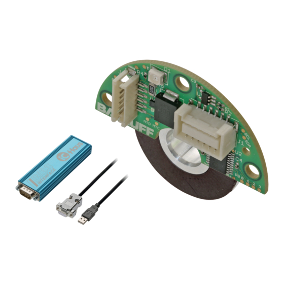
BAV AS-LP-00008-01 / BAE PD-AV-006 Evaluation-System Aufbau und Funktion Übersicht Systemkomponenten BAE PD-AV-006 BAV AS-LP-00008-01 serielles Kabel D-Sub-Stecker (male) USB-Kabel serielles Kabel inkrementelles Kabel BiSS-USB-Adapter Steuerung Auswerte- absolut magnetkodierte elektronik Scheibe Bild 3-1: Komponentenübersicht Absolut magnetkodierte Scheibe Auswerte elektronik Die magnetkodierte Scheibe kann einzeln nachbestellt werden (Typenschlüssel:... -
Page 8: Einbau Und Anschluss
BAV AS-LP-00008-01 / BAE PD-AV-006 Evaluation-System Einbau und Anschluss Abstände, Winkel und Toleranzen –Pitch +Pitch +Yaw –Yaw +Roll –Roll –X Aktive Messfläche Verfahrrichtung vorwärts A vor B, SSI- oder BiSS-Position zunehmend Drehwinkel (siehe auch Bild 7-6 auf Seite 27) Bild 4-1: Abstände, Winkel und Toleranzen... -
Page 9: Winkelmesssystem Montieren
BAV AS-LP-00008-01 / BAE PD-AV-006 Evaluation-System Einbau und Anschluss (Fortsetzung) Winkelmesssystem montieren ACHTUNG Entladeströme ACHTUNG Elektrostatische Entladungen können Bauteile zerstören. ► ESD-Schutzmaßnahmen treffen! Funktionsbeeinträchtigung Unsachgemäße Montage der magnetkodierten Scheibe und der Auswerte elektronik kann die Funktion des Bei der Montage von Scheibe und Auswerte elektronik sind Winkelmesssystems beeinträchtigen und zu erhöhtem... -
Page 10: Elektrischer Anschluss
BAV AS-LP-00008-01 / BAE PD-AV-006 Evaluation-System Einbau und Anschluss (Fortsetzung) Elektrischer Anschluss Anschließen für den Analog-/Digitalbetrieb ► Auswerte elektronik (Steckplatz J1) über inkrementelles Kabel mit der Steuerung verbinden. ACHTUNG ► Auswerte elektronik (Steckplatz J2) über serielles Kabel Entladeströme mit der Spannungsversorgung verbinden. -
Page 11: Usb-Kabel
BAV AS-LP-00008-01 / BAE PD-AV-006 Evaluation-System Einbau und Anschluss (Fortsetzung) 4.3.1 USB-Kabel 4.3.3 Serielles Kabel – Zur Verbindung des Adapters mit dem Konfigurations- – Zur Verbindung der Auswerteeinheit mit der Steuerung – Betriebsspannung und BiSS-/SSI-Schnittstelle – Betriebsspannung und Konfigurationsdaten –... -
Page 12: Biss-Usb-Adapter
BAV AS-LP-00008-01 / BAE PD-AV-006 Evaluation-System Einbau und Anschluss (Fortsetzung) 4.3.4 BiSS-USB-Adapter Weitere Informationen zum Programmieradapter finden Sie im Internet unter www.ichaus.de. Magnetfelder und Kabelverlegung Magnetfelder Das Winkelmesssystem ist ein magnetkodiertes System. Auf ausreichenden Abstand des Winkelmesssystems zu starken externen Magnetfeldern achten. -
Page 13: Software
BAV AS-LP-00008-01 / BAE PD-AV-006 Evaluation-System Software Softwareübersicht Installation Die Software (MU1C-Evaluation-GUI (Graphical User Voraussetzung für die volle Funktionsfähigkeit Interface)) stellt die grafische Benutzeroberfläche zur ist ein USB-2.0-Port. intuitiven Einstellung der Schnittstellenparameter und der Der USB-Adapter sollte direkt mit dem PC Kalibrierung des Evaluation-Systems dar. -
Page 14: Benutzeroberfläche
BAV AS-LP-00008-01 / BAE PD-AV-006 Evaluation-System Software (Fortsetzung) Benutzeroberfläche Status-Textfeld Bild 5-1: Benutzeroberfläche Die Benutzeroberfläche ist funktionell in 2 Blöcke unterteilt: 1. Programming and Calibration für Parametrier- und 2. Open Measurement Window zur Positionserfassung Kalibrierfunktionen und -anzeige Aufrufen der Funktionen durch Klicken auf die Schalt- Aufrufen der Funktion durch Klicken auf die Schaltflä-... -
Page 15: Kalibrier- Und Parametrierfunktionen
BAV AS-LP-00008-01 / BAE PD-AV-006 Evaluation-System Software (Fortsetzung) 5.5.2 Datenintegrität und Performance Kalibrier- und Parametrierfunktionen Die maximale Länge der Kalibrierroutine hängt von der 5.5.1 Funktionale Bereiche innerhalb der Kalibrier- Größe des Arbeitsspeichers sowie der Prozessorleistung und Parametrierfunktion Für die Kalibrierfunktion gibt es auf der Benutzeroberfläche... - Page 16 BAV AS-LP-00008-01 / BAE PD-AV-006 Evaluation-System Software (Fortsetzung) 5.5.3 Kalibrierroutine Die durch die Kalibrierung erreichte System- genauigkeit ist bei der automatischen Kalibrie- Kalibrierroutine aufrufen rung immer besser als bei der manuellen Kali- ► Parametrierung über n brierung. ensor heCk oWer starten.
- Page 17 BAV AS-LP-00008-01 / BAE PD-AV-006 Evaluation-System Software (Fortsetzung) 5.5.5 Anzeigeelemente der Kalibrierroutine Calibration-OK-LED System Conditions – Track Offset – Margin Of Safety (System-Sicherheit) Die Calibration-OK-LED leuchtet, sobald die Kalibrierung der Phasen des Analogpfads reproduzierbar über mehrere Messreihen (Abweichungen < 0,5°) ist. 5.5.6 Fehler bei der Kalibrierung Treten bei der Kalibrierung Fehler auf, können die Ursa-...
- Page 18 BAV AS-LP-00008-01 / BAE PD-AV-006 Evaluation-System Software (Fortsetzung) 5.5.7 Experten-Parametrierung BiSS Pos. Data Length Hysteresis/Latency Einstellung der Hysterese und der Latenzzeit. Im Sensor können verschiedene Filter für die Positionserfassung gewählt werden. Einstellung der Positionsdatenlänge für die BiSS-Schnitt- stelle: – Fixed (19 Bit, default): Standardeinstellung, Datenlänge auf 19 Bit festgelegt (Beispiel siehe Bild 7-3).
- Page 19 BAV AS-LP-00008-01 / BAE PD-AV-006 Evaluation-System Software (Fortsetzung) Positionserfassung und -anzeige (Measure) Schalt- Funktion fläche Starten der Positionserfassung/-anzeige Schließt das Messwerterfassungsfenster, lose ► Auf die Schaltfläche m ) klicken. Spannung ist aus. easure oWer on oWer Tab. 5-2: Schaltflächen des Messwerterfassungsfensters Das Messwerterfassungsfenster ist in 2 Teile gegliedert.
- Page 20 BAV AS-LP-00008-01 / BAE PD-AV-006 Evaluation-System Software (Fortsetzung) Funktionsübersicht Funktion (Nr.)* Element Beschreibung Programming Schalt- New Sensor / Schaltet die Versorgungsspannung ein und initialisiert die Auswerte elektronik (die and Calibration fläche Check In Auswerteelektronik wird in den Konfigurationsmodus gesetzt und darf bis zum Funk-...
- Page 21 BAV AS-LP-00008-01 / BAE PD-AV-006 Evaluation-System Inbetriebnahme System in Betrieb nehmen Systemfunktion prüfen Nach der Montage des Winkelmesssystems oder dem GEFAHR Austausch einer Komponente sämtliche Funktionen wie folgt prüfen: Unkontrollierte Systembewegungen 1. Continuous Read (Softwarefunktion im Messwerterfas- Bei der Inbetriebnahme und wenn die Winkelmess- sungsfenster) starten und eine ganze Umdrehung über-...
- Page 22 Registerkommunikation: zur Übertragung der Positionsdaten und hat keinen Ein- Mit jedem Frame kann ein Bit von der Steuerung zur fluss auf das Messverhalten des Systems. Die Balluff Auswerteelektronik übertragen werden. Dazu wird BiSS-C-Messsysteme können über eine Punkt-zu-Punkt- während der t -Zeit (siehe Time Out adaptiv in Kapi-...
- Page 23 BAV AS-LP-00008-01 / BAE PD-AV-006 Evaluation-System Schnittstellen (Fortsetzung) 7.1.2 Datenformat (BiSS-Frame) Clock-Rate (T_CLK) 50 kHz < f_CLK < 10 MHz wobei f = 1/T CLK Time Out (T_M) Adaptiv (typ. T =2 × t_CLK, jedoch t < 20 μs) Min. Wiederholrate (f = 35 × t_CLK + 0,5 μs mit (Zeit zwischen = 1/TA...
- Page 24 BAV AS-LP-00008-01 / BAE PD-AV-006 Evaluation-System Schnittstellen (Fortsetzung) 7.1.3 BiSS-Frame (allgemein) Latch Position BiSS Start = CDS = D18 = D0 = Data ...Busy... Position (right-aligned) Data-Range n + 8 Bit (n × Data + Error + Warning + 6 × CRC) (n ist von den Einstellungen BiSS Pos.
- Page 25 BAV AS-LP-00008-01 / BAE PD-AV-006 Evaluation-System Schnittstellen (Fortsetzung) 7.1.6 BiSS C unidirektional 7.1.7 BiSS C bidirektional (Statusregister) Das Evaluation-System unterstützt grundsätzlich BiSS C Bei der BiSS-C-Schnittstelle werden Fehler und War- bidirektional, ist jedoch durch seine Abwärtskompatibilität nungen (E/W-Ereignisse) im seriellen Datensatz übertra- auch fähig, BiSS C unidirektional zu übertragen.
- Page 26 BAV AS-LP-00008-01 / BAE PD-AV-006 Evaluation-System Schnittstellen (Fortsetzung) Synchron-serielle Schnittstelle (SSI) Das Evaluation-System hat werkseitig folgende Einstellun- gen für die Datenübertragung, die nachträglich nicht mehr 7.2.1 Prinzip verändert werden können: SSI bedeutet Synchronous Serial Interface und beschreibt Clock-Frequenz 50 kHz < f_CLK < 4 MHz eine digitale synchrone Schnittstelle mit einer differenziellen Time Out...
- Page 27 BAV AS-LP-00008-01 / BAE PD-AV-006 Evaluation-System Schnittstellen (Fortsetzung) 7.3.2 Digitale Schnittstelle (RS422) Inkrementelle Schnittstelle Digitales inkrementelles Messsystem 7.3.1 Analoge Schnittstelle (1 V Die Auswerteelektronik überträgt die Messgröße als diffe- Bei den analogen Sinus- und Cosinussignalen +A (+Sin), renzielles Spannungssignal (RS422) an die Steuerung.
- Page 28 BAV AS-LP-00008-01 / BAE PD-AV-006 Evaluation-System Schnittstellen (Fortsetzung) 7.3.3 Maximale Drehgeschwindigkeit, Auflösung Auflösung (Inkremente Winkelauflösung in und Flankenabstand je Umdrehung) Winkelgrad (je Inkre- ment (LSB)) Die Auswahl der Auflösung und des Flankenabstandes bestimmt die maximale Drehgeschwindigkeit, die der ca. 0,703 Sensor noch erkennen kann.
- Page 29 BAV AS-LP-00008-01 / BAE PD-AV-006 Evaluation-System Technische Daten Absolut magnetkodierte Scheibe Kodierung magnetischer 2-Spur-Nonius Luftspalt 0,1…0,5 mm Systemgenauigkeit mit < ±0,2° absolut iC-MU (Fehler je Drehung) Drehzahl ≤12.000 Umdrehungen/min Betriebstemperatur −40…+85 °C Polbreite 1,28 mm/0,96 mm (Master-/Noniusspur) Anzahl Polpaare 32/31 (Master-/Noniusspur) Außendurchmesser 30 mm Innendurchmesser Höhe...
- Page 30 US Service Center CN Service Center Germany Germany China Balluff GmbH Balluff GmbH Balluff Inc. Balluff (Shanghai) trading Co., ltd. Schurwaldstrasse 9 Schurwaldstrasse 9 8125 Holton Drive Room 1006, Pujian Rd. 145. 73765 Neuhausen a.d.F. 73765 Neuhausen a.d.F. Florence, KY 41042 Shanghai, 200127, P.R.
- Page 31 BAV AS-LP-00008-01 BAE PD-AV-006 User’s Guide english...
- Page 32 www.balluff.com...
- Page 33 BAV AS-LP-00008-01/BAE PD-AV-006 Evaluation System Notes to the user Validity Symbols and conventions Scope of delivery System requirements Abbreviations Safety Intended use General safety notes for the angle measuring system Component safety and protection Explanation of the warnings Disposal Construction and function...
- Page 34 BAV AS-LP-00008-01/BAE PD-AV-006 Evaluation System Interfaces BiSS C interface 7.1.1 Principle 7.1.2 Data format (BiSS frame) 7.1.3 BiSS frame (general) 7.1.4 BiSS frame - example resolution = 131,072, fixed data length 7.1.5 BiSS frame - example resolution = 32,768, flexible data length 7.1.6 Uni-directional BiSS C 7.1.7 Bi-directional BiSS C (status register)
-
Page 35: Notes To The User
BAV AS-LP-00008-01/BAE PD-AV-006 Evaluation System Notes to the user Scope of delivery BAV AS-LP-00008-01 The Evaluation System was developed in collaboration – Absolute magnetically coded disk with iC-Haus GmbH. – Processing electronics (MU1C) – Cable set for electronics and controller Validity... -
Page 36: Safety
Thus, suitable ESD safety precautions must be taken the technical data is ensured only when using original during assembly and connection. BALLUFF accessories. Use of any other components will void the warranty. Explanation of the warnings Non-approved use is not permitted and will result in the... -
Page 37: Construction And Function
BAV AS-LP-00008-01/BAE PD-AV-006 Evaluation System Construction and function System component overview BAE PD-AV-006 BAV AS-LP-00008-01 Serial cable D-Sub plug (male) USB cable Serial cable Incremental cable BiSS USB adapter Controller Processing Absolute magnetically electronics coded disk Fig. 3-1: Component overview... -
Page 38: Installation And Connection
BAV AS-LP-00008-01/BAE PD-AV-006 Evaluation System Installation and connection Angles, distances, and tolerances –Pitch +Pitch +Yaw –Yaw +Roll –Roll –X Active measuring surface Forwards direction of travel, A before B, SSI or BiSS position rising Rotation angle (see also Fig. 7-6 on page 27) Fig. - Page 39 BAV AS-LP-00008-01/BAE PD-AV-006 Evaluation System Installation and connection (continued) Assembling the angle measuring system NOTICE Discharge currents NOTICE Electrostatic discharges can destroy components. ► Take ESD safety precautions! Interference in function Improper assembly of the magnetically coded disk and processing electronics can affect the functioning of the...
- Page 40 BAV AS-LP-00008-01/BAE PD-AV-006 Evaluation System Installation and connection (continued) Electrical connection Connection for analog/digital operation ► Connect the processing electronics (slot J1) to the controller using the incremental cable. NOTICE ► Connect the processing electronics (slot J2) to the Discharge currents supply voltage using the serial cable.
- Page 41 BAV AS-LP-00008-01/BAE PD-AV-006 Evaluation System Installation and connection (continued) 4.3.1 USB cable 4.3.3 Serial cable – For connecting the adapter to the configuration – For connecting the evaluation unit to the controller computer – Operating voltage and BiSS/SSI interface –...
- Page 42 BAV AS-LP-00008-01/BAE PD-AV-006 Evaluation System Installation and connection (continued) 4.3.4 BiSS USB adapter You can find additional information on the programming adapter online at www.ichaus.de. Magnetic fields and cable routing Magnetic fields The angle measuring system is a magnetically coded system.
- Page 43 BAV AS-LP-00008-01/BAE PD-AV-006 Evaluation System Software Software overview Installation The software (MU1C Evaluation GUI) is the graphical user A USB 2.0 port is required for full functionality. interface for intuitive configuration of interface parameters The USB adapter should be connected directly and calibrating the Evaluation System.
- Page 44 BAV AS-LP-00008-01/BAE PD-AV-006 Evaluation System Software (continued) User interface Status text field Fig. 5-1: User interface The user interface is divided into 2 functional blocks: 1. Programming and Calibration for parameterization and 2. Open Measurement Window for position detection and calibration functions...
- Page 45 BAV AS-LP-00008-01/BAE PD-AV-006 Evaluation System Software (continued) 5.5.2 Data integrity and performance Calibration and parameterization functions The maximum length of the calibration routine depends on 5.5.1 Functional areas within the calibration and the amount of RAM and the processor. parameterization functions...
- Page 46 BAV AS-LP-00008-01/BAE PD-AV-006 Evaluation System Software (continued) 5.5.3 Calibration routine The system accuracy achieved through calibration is always better with automatic Calling up the calibration routine calibration than manual calibration. ► Start parameterization via n ensor heck Automatic calibration calibrates both the analog path and ower ⇒...
- Page 47 BAV AS-LP-00008-01/BAE PD-AV-006 Evaluation System Software (continued) 5.5.5 Calibration routine display elements Calibration OK LED System Conditions – Track Offset – Margin Of Safety The calibration OK LED lights up as soon as the calibration of the analog path phases can be reproduced across multiple series of measurements (deviations < 0.5°).
- Page 48 BAV AS-LP-00008-01/BAE PD-AV-006 Evaluation System Software (continued) 5.5.7 Expert parameterization BiSS pos. data length Hysteresis/latency Setting the hysteresis and latency. Different filters for position detection can be selected in the sensor. Setting the position data length for the BiSS interface: –...
- Page 49 BAV AS-LP-00008-01/BAE PD-AV-006 Evaluation System Software (continued) Position detection and display (measure) Button Function Closes the parameter acquisition window; lose Starting position detection/display voltage is off. ower ► Click the M ) button. easUre ower on Tab. 5-2: Parameter acquisition window buttons The parameter acquisition window is divided into 2 parts.
- Page 50 BAV AS-LP-00008-01/BAE PD-AV-006 Evaluation System Software (continued) Overview of functions Function (no.)* Element Description Programming Button New sensor / Switches the supply voltage on and initializes the processing electronics (the and Calibration Check In processing electronics are set to configuration mode and may no longer be removed...
- Page 51 BAV AS-LP-00008-01/BAE PD-AV-006 Evaluation System Startup Starting up the system Check system function Check all functions as follows after assembling the angle DANGER measuring system or exchanging a component: 1. Start Continuous Read (software function in the Uncontrolled system movement...
- Page 52 (see Adaptive timeout in 7.1.2). The effect on the system's measuring behavior. The Balluff processing electronics recognize it as a high or low bit BiSS C measuring systems can be connected to the (CDM) and mirror it in the CDS bit in the next frame.
- Page 53 BAV AS-LP-00008-01/BAE PD-AV-006 Evaluation System Interfaces (continued) 7.1.2 Data format (BiSS frame) Clock rate (T_CLK) 50 kHz < f_CLK < 10 MHz where f = 1/T CLK Timeout (T_M) Adaptive (typ. T =2 × t_CLK, but t < 20 μs) Min. repeat rate (f = 35 × t_CLK + 0.5 μs with (time between = 1/TA...
- Page 54 BAV AS-LP-00008-01/BAE PD-AV-006 Evaluation System Interfaces (continued) 7.1.3 BiSS frame (general) Latch Position BiSS Start = CDS = D18 = D0 = Data ...Busy... Position (right-aligned) Data-Range n + 8 Bit (n × Data + Error + Warning + 6 × CRC) (n is dependent on the BiSS Pos.
- Page 55 BAV AS-LP-00008-01/BAE PD-AV-006 Evaluation System Interfaces (continued) 7.1.6 Uni-directional BiSS C 7.1.7 Bi-directional BiSS C (status register) The Evaluation System generally supports BiSS C in both With the BiSS C interface, errors and warnings (E/W directions, but is also capable of uni-directional BiSS C events) are transmitted in the serial data set.
- Page 56 BAV AS-LP-00008-01/BAE PD-AV-006 Evaluation System Interfaces (continued) Synchronous Serial Interface (SSI) At the factory, the Evaluation System has the following settings for data transfer that cannot be changed later: 7.2.1 Principle Clock frequency 50 kHz < f_CLK < 4 MHz SSI stands for Synchronous Serial Interface and describes Timeout 20 μs...
- Page 57 BAV AS-LP-00008-01/BAE PD-AV-006 Evaluation System Interfaces (continued) 7.3.2 Digital interface (RS422) Incremental interface Digital incremental measuring system 7.3.1 Analog interface (1 V The processing electronics transmit the measurement as a With the analog sine and cosine signals +A (+sin), −A (−...
- Page 58 BAV AS-LP-00008-01/BAE PD-AV-006 Evaluation System Interfaces (continued) 7.3.3 Maximum rotational speed, resolution, and Resolution (increments Angular resolution in edge distance per revolution) angular degrees (per increment (LSB)) The selection of the resolution and edge distance determines the maximum rotational speed that the sensor Approx.
- Page 59 BAV AS-LP-00008-01/BAE PD-AV-006 Evaluation System Technical data Absolute magnetically coded disk Coding Magnetic 2-track Nonius 0.1 to 0.5 mm System accuracy with < ±0.2° absolute IC-MU (error per revolution) Rotational speed ≤12,000 revolutions/minute Operating temperature −40 to +85°C Pole width 1.28 mm/0.96 mm...
- Page 60 US Service Center CN Service Center Germany Germany China Balluff GmbH Balluff GmbH Balluff Inc. Balluff (Shanghai) trading Co., ltd. Schurwaldstrasse 9 Schurwaldstrasse 9 8125 Holton Drive Room 1006, Pujian Rd. 145. 73765 Neuhausen a.d.F. 73765 Neuhausen a.d.F. Florence, KY 41042 Shanghai, 200127, P.R.
Need help?
Do you have a question about the BAV AS-LP-00008-01 and is the answer not in the manual?
Questions and answers