NANO 3 Series, NBA-2110, NBA-2120, NBA-3120 Manual
- User manual (24 pages) ,
- User manual (28 pages)
Advertisement
- 1 General Information
- 2 Technical Description
- 3 Technical Specification
- 4 Product Contents
- 5 Unpacking Guide
- 6 Product Dimensions
- 7 Equipment Overview
- 8 Typical System Layout
- 9 Mechanical Installation
- 10 Electrical Installation
- 11 Unit Operation
- 12 Maintenance
- 13 Servicing
- 14 Troubleshooting
- 15 General safety
- 16 Documents / Resources
General Information
Support and Manufacturers details
nano-purification solutions inc.
5509 David Cox Road
Charlotte,
NC 28269
USA
Telephone: +1 (704) 897-2182
Fax: +1 (704) 897-2183
Internet: www.n-psi.com ;
E-mail: support@n-psi.com
nano-purification solutions ltd.
Dukesway,
Team Valley Trading Estate,
Gateshead,
NE11 0PZ
United Kingdom
Telephone: +44 (0) 191 497 7700
Fax: +44 (0) 191 497 7709
Internet: www.n-psi.co.uk
E-mail: enquiries@n-psi.co.uk
Annotations:
 CAUTIONS: indicate any situation or operation that may result in potential damage to the product, injury to the user, or render the product unsafe.
 NOTES: highlight important sections of information where particular care and attention should be paid.
Packaging
All products are securely packaged in a specifically designed wooden packing box. The purifier will be held in a horizontal position by wooden struts; using straps to secure the product to the box base. The box top cover can be removed by removing all of the fixing screws and lifting it off in one piece.
Damage to Packaging
- Check immediately to establish whether damage has occurred to the external packaging and if the damage extends to the product inside.
- If there is damage to a product, contact the relevant supplier immediately.
In no circumstances must a damaged product be used in operation. Using damaged products can lead to irreparable functional faults or cause serious physical harm.
Technical Description
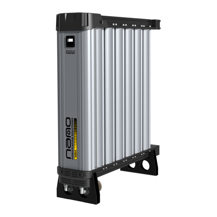
High purity compressed medical breathing air purifiers.
The nano Breathing Air Systems (NBA) range of medical compressed breathing air purifiers are designed to provide a continuous supply of breathable air to meet the most exacting standards worldwide. The unique design provides a major step forward in compactness by incorporating several stages of purification in one simple to service cartridge, reducing the cost of ownership and simplifying maintenance.
Atmospheric air contains a number of contaminants which must be removed to ensure the provision of high purity breathable air. Contaminants present include dirt, water, oil, hydrocarbon vapors, bacteria and toxic gases such as CO, NO2 and SO2.
The nano breathing air purifier employs a number of purification stages to ensure breathable compressed air is produced from a typical compressed air supply. Inlet filtration removes dirt, bulk water and oil aerosols (if an oil lubricated compressor is used). Water vapor and hydrocarbon vapors are removed by selected adsorbents and CO2 reduces to within specified levels. CO is removed by a catalytic stage and finally all residual dust and bacteria are removed by the integrated high efficient outlet filter. Internally, should small amounts of bulk liquid enter the purifier, they will be separated and safely drained away by reliable solenoid valves that are also used in the operation of the pressure swing adsorption process.
How the breathing air NBA purifier works:
The nano breathing air purifiers use the pressure swing adsorption principle to efficiently purify the compressed air. They consist of a twin tower configuration of modular construction. Each tower contains a composite purification cartridge which incorporates various types of selected materials to remove impurities to within the required levels.
Moist contaminated air enters the purifier and is first directed to column A. The air passes into the purification cartridge where water vapor is adsorbed and the air dried to a level that enables the CO to be converted to CO2 by the use of a catalyst. CO2 content is also adsorbed to ensure the outlet purity is achieved but enough is left for respiratory purposes. Hydrocarbon vapors, NO2 and SO2 contaminants are now adsorbed using a selected high surface area activated carbon stage. Finally the air passes through a high efficiency filter stage to remove any solid particles and bacteria. Simultaneously, a small amount of purified air is depressurized and counter flowed through Column B and exhausted to atmosphere, removing the moisture and excess CO2. Hydrocarbon vapors NO2 and SO2 are retained on the activated carbon stage through chemisorptions. Column A typically operates for 2 minutes while column B is under regeneration (1 ½ minutes of purge and then repressurized) prior to the columns being switched over, which brings Column B on line and Column A goes into regeneration.
The breathing air purifier is controlled by a robust PLC which switches the solenoid valves allowing each column to be switched from purifying to regeneration thus providing a continuous stream of purified breathing air.
Technical Specification
Product Specification
| Required Inlet Purity | ISO 8573-1: 2010 Class 1:2:2 |
| Minimum working pressure | 80 psig (5.5 barg) |
| Maximum working pressure | 145 psig (10 barg) |
| Power Supply | 100 - 240v AC / 50 - 60Hz |
| Minimum inlet temperature | 34.7°F (1.5°C) |
| Maximum inlet temperature | 86°F (30°C) |
| Ambient Temperature | 34-122°F (1-50°C) |
| IP Rating | IP54 / NEMA 3 |
| Power | 38W |
| Noise | <90dB (A) |
Breathing Air Standards
| Impurity | European Pharma | CSA Z180.1 | NBA Medical Breathing Air Purifier |
| *CO2 | <500ppm | <500ppm | <500ppm ♦1 |
| *CO | <5ppm | <5ppm | <5ppm ♦2 |
| SO2 | <1ppm | NA | <1ppm |
| NO2 | <2ppm | NA | <2ppm |
| O2 | NA | 20-22% | 20-22% |
| N2 & Rare Gases | NA | 78-80% | 78-80% |
| Water Vapour | ADP -45°C (-49°F) (-23°F) -31°C at 7 bar (100psi) | At a dew point 5°C under the lowest temperature its exposed to during the year. | PDP better than -40°F (-40°C) to ensure effective operation of the catalyst. |
| Oil vapour | <0.01 mg/m³ | <1mg/m3 | <0.01mg/m3 |
| Dirt Particles | NA | <1mg/m3 | Down to 0.01 micron |
| Odour | Taste and odour free | Taste and odour free | Taste and odour free |
| Bacteria | NA | NA | Removed (DOP efficiency 99.999%) |
| Methane | NA | <10ppm | <10ppm |
| Volatile non-methane hydrocarbons (VNMH) | NA | <5ppm | <5ppm |
| Volatile halogenated hydrocarbons | NA | <5ppm | <5ppm |
| Europe | EN12021 | ||
| UK | BS4275: 1997 | ||
| USA | CGA G7.1-1997 OSHA-Grade D | ||
| Canada | CSA Z180.1 | ||
Refer to "Sampling" section regarding sampling and maintaining standards.
*Where excessive levels of CO2 and CO have been indentified as the norm, breathing air purifiers should not be used and alternative strategies should be derived from a risk assessment.
When challenged with 750ppm ♦1
When challenged with 65ppm ♦2
All breathing air systems should be proceeded by high efficiency filtration regardless of whether an oil or oil free compressor is used. Inlet air should be filtered such that it complies with ISO 8573-1: 2010 quality classes.
Maximum Flow Rates at 102psig/7barg and temperature of 75°F/24°FC
| Model | Inlet Flow | Outlet Flow | ||
| NL/m | scfm | NL/m | scfm | |
| NBA - 2110 | 4871 | 172 | 3653 | 129 |
| NBA - 2120 | 6117 | 216 | 4588 | 162 |
| NBA - 3120 | 9176 | 324 | 6882 | 243 |
| NBA - 4120 | 12234 | 432 | 9176 | 324 |
| NBA - 6120 | 18351 | 648 | 13764 | 486 |
For flow rates at other pressures, apply the factor shown:
| Line Pressure | bar g | 5.5 | 6 | 7 | 8 | 9 | 10 |
| psi g | 80 | 87 | 102 | 116 | 131 | 145 | |
| Correction Factor | 0.89 | 0.92 | 1 | 1.07 | 1.13 | 1.20 | |
CO Alarm
According to OSHA 1910.134 and CSA Z180.1, should be fitted to monitor the outlet air purity.
Product Contents
- Series 3 Breathing Air Purifier
- Documentation
- 1 x User Guide
- 1 x Declaration of Conformity
- Packaging
- 1 x Purifier support base and box cover
Suitable inlet filtration not included.
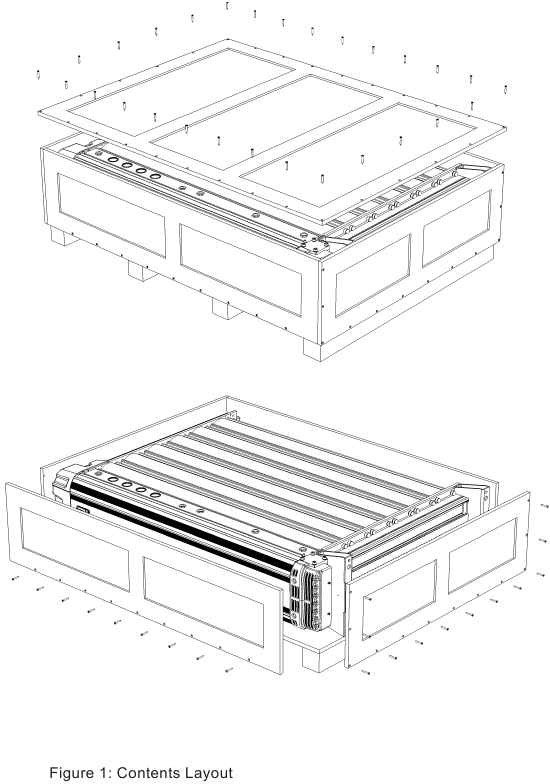
See Figure 1
Unpacking Guide

The purifier is supplied in a wooden crate. It is recommended that the crate be moved into position using a forklift truck or pallet truck. Remove the purifier from the wooden crate using an overhead crane. Use the above illustrations for correct guidance on safe handling and lifting techniques.
- Cut packaging straps first, before lifting.
Ensure that the external silencers/mufflers are removed before attempting to lift the purifier.
Product Dimensions

| MODEL | CONNECTION | A ins (mm) | B ins (mm) | C ins (mm) | D ins (mm) | E ins (mm) | WEIGHT lbs (KG) |
| NBA - 2110 | 2" NPT | 26 (678) | 15 (382) | 50 (1289) | 16 (400) | 14 (360) | 366 (166) |
| NBA - 2120 | 2" NPT | 26 (678) | 15 (382) | 60 (1538) | 16 (400) | 14 (360) | 441 (200) |
| NBA - 3120 | 2" NPT | 31 (781) | 21.6 (550) | 60 (1538) | 16 (400) | 14 (360) | 778 (353) |
| NBA - 4120 | 2.5" NPT | 38 (949) | 28 (718) | 60 (1538) | 16 (400) | 14 (360) | 1010 (548) |
| NBA - 6120 | 2.5" NPT | 51 (1285) | 41.5 (1054) | 60 (1538) | 16 (400) | 14 (360) | 1155 (524) |
Equipment Overview

| 1 | Purifier Top Cover | 2 | Controller Display Unit |
| 3 | Front Shroud | 4 | Purifier Column |
| 5 | Air Outlet | 6 | Air Inlet |
| 7 | External Silencers/Mufflers | 8 | Mains Power |
| 9 | Remote Stop/Start Control (if required) |
Typical System Layout

| Ref. | Description | Ref. | Description |
| 1 | Compressor | 5 | Series 3 Purifier |
| 2 | Wet air receiver | 6 | Oil / water separator |
| 3 | Water separator | 7 | Pressure Relief Valve* |
| 4 | Purifier pre-filtration |
It is the customer's responsibility to fit pressure relief valves to the compressed air system.
Site Location
When selecting an installation site for the purifier, ensure the following conditions are met:
- Installation site should be located indoors on a flat surface protected from the weather and other harmful conditions.
- The inlet temperature must not drop below 35°F (+1.5°C) or exceed 86°F (30°C).
- The installation site should be level and able to support the weight of the product.
- Ensure sufficient space around the product, to allow access for operation and maintenance.
Risk Assessment
Prior to the installation a thorough risk assessment of the entire installation should be conducted by a competent person. Points listed below should be considered but should not be considered as exhaustive:
- Compressor type
- Condition of compressor/oil used if applicable
- Temperature and humidity
- Potential source of excessive contaminants e.g. toxic gases
- Use of a dedicated breathing air line if possible
- Purification equipment
- Alarm options
- Compliance to relevant regulations for pressured systems
- Comprehensive operator training
- Maintenance requirements
- Suitable warning signs posted
The risk assessment should be carried out by suitable personnel and checked and approved by a suitably qualified engineer.
A CO alarm must be fitted to the outlet of the purifier.
Mechanical Installation

Once the purifier has been positioned and secured, install ball valves and pipe work (not included) to ready the unit for connection to inlet and outlet pressure piping.
The diameter of the pipes must be sufficient to allow unrestricted inlet air supply to the purifier and to the application as shown in the table below.
| Ref. | Description | Ref. | Description |
| 1 | Ball Valve | 4 | High efficiency FIlter (inlet) |
| 2 | Water Separator (inlet) | 5 | 2" / 2.5" Piping (as required by the purifier) |
| 3 | Pre-filter (inlet) | 6 | Series 3 Purifier |
A water separator and high efficiency filtration must be installed at the inlet to the purifier.
Ensure that each filter condensate drain is suitably piped away and any effluent is disposed of in accordance with local regulations.
It is important to ensure that all piping materials are suitable for the application, clean and debris free. The diameter of the pipes must be sufficient to allow unrestricted inlet air supply to the equipment and outlet air supply to the application. The purifier is supplied with an integrated exhaust silencer.
All components used within the system must be rated to at least the maximum operating pressure of the equipment. The system must be protected with suitably rated pressure relief valves.
Electrical Installation

Mains Power Connection (See Figures 1-3)
To install the mains power cable:
- Remove the two screws from the top cover and lift from the purifier.
- Locate the two catches at the top and bottom of the shroud and pull them towards each other and open the shroud to expose the controller.
- Remove the IEC plug from the controller
- Unscrew the cap head screw to remove the plug top cover.
- Feed the mains power cable through the holes located on the bottom of the shroud.
- Wire the mains power cable into the IEC plug (see figure 2).
- Once the mains cable is correctly wired into the IEC plug, reattach the plug into its socket.
| Electrical Power Requirements | |
| Supply: | 100 - 240VAC 50-60 Hz |
| Input Current: | 1.3 / 0.8A (115/230 VAC) |
Unit Operation
Locate the electrical connector on the underside of the controller in the shroud.
Unit Remote Stop/Start Control
(if required)

See Figure 1
- To set up for remote control eco mode. Remove the link between pins 1 and 4 (3) in the electrical connector plug. A zero volt switching signal from the remote control needs to be connected between pins 1 and 4 (4).
- When the connection is made, the purifier will operate normally. If the connection is broken, i.e. the purifier has been remotely switched off, the purifier will stop cycling and go into standby mode, displaying "STANDBY" on the display once completed.
- Using remote stop / start ensures the correct shut-down sequence is implemented.
6 Pin Electrical Connector Configuration

Under no circumstances should external voltage/current be applied to pins 1 and 4, damage to the controller will occur, negating the warranty.
Device Start-up
- Ensure the purifier is securely hardwired into the power source.
Do not allow the purifier to flow air unless powered up, switched on and cycling. Resulting effect could be bed contamination; requiring replacement cartridges.
Ensure that the external silencers/mufflers are re-installed before attempting to start the purifier.
- Connect all pipe work.
- Ensure the inlet operating pressure parameters are between 80 - 145 psig (5.5 - 10 barg).
- Ensure the inlet air temperature is between 35°F - 86°F (1.5 - 30°C).
- Slowly open the inlet valve until fully open and allow purifier to pressurize.
- Turn on the power to the purifier.
- Open the outlet valve.
- The purifier will display its status and commence normal operation.
The dew point alarm is inactive for the first 5 hours after start up to allow the purifier to hit dew point. The process gas should not be used for breathing air purposes during this time.
Monitor CO levels in outlet
- Where regulation demand, a suitable CO alarm must be fitted (not supplied). Provision is made to allow a small bleed of air to be taken from the outlet of the Purifier.
- Where a CO alarm is not fitted (not required by local regulation) an alternative indication of performance may be acheived by monitoring the dryness of the air (10.4). The catalyst only functions with dry air.
Monitoring Device Performance with Energy saving option

- The dew-point is displayed on the control panel. When the dew-point displayed is better than -67°F (-55°C) PDP the Purifier will switch into economy mode and stop cycling. When the dew-point degrades to -58°F (-50°C) the Purifier will restart cycling ensuring the dew-point is maintained at or better than -58°F (-50°C).
- If the Purifier fails to achieve dew-point (falls below -40°F (-40°C)) the alarm output will be indicated on the front screen and the remote alarm output will activate.
Shutdown Procedure
- Close the inlet and outlet valves.
The purifier will still be pressurized! In order to depressurize the purifier; ensure the purifier is isolated from the compressed air supply source:
- Cycle the purifier at least twice to ensure the purifier exhausts and is completely depressurized.
- When fully depressurized the 'clicking' of the exhaust valves will be heard but no air exhausted.
- When the purifier is fully depressurized, isolate from the power supply.
Maintenance
Cleaning
Clean the equipment with a damp cloth only and avoid excessive moisture around any electrical sockets. If required a mild detergent may be used, however do not use abrasives or solvents as they may cause damage.
Daily Checks
Visual and functional checks of the purifier should be carried out daily:
- Check the purifier for any external damage.
Assess and eliminate any defects found. - If the red service light appears, the purifier must be serviced.
Contact the service department and request a purifier service kit. - Remove any loose dust or dirt from the purifier; clean all surfaces that appear to have attracted unwanted contaminants.
- Check the dewpoint sensor display (if installed). If the dewpoint is not maintained at <-30°C the reading on the display will alternate with "dewpoint alarm" every 5 seconds. The no-volt alarm will also activate.
Sampling
A sample of compressed breathing air produced and delivered by the compressed breathing air system must be collected and analyzed every 6 months (or as specificed by the authority having jurisdiction) by an accredited lab. When the testing shows unacceptable levels of contaminants, the system must be taken out of service and reinspected.
- Additional testing at regular intervals is recommended.
- Re-testing the system is recommended when any major overhaul or extensive repairs have been carried out.
Any noticeable odour must be analyzed.
Servicing
 Maintenance operations should only be carried out by competent and suitably trained personnel.
Servicing Guidelines
- Maintenance operations only to be conducted when the system has been shut down, fully depressurized and isolated completely from the compressed air and electrical supply.
- Ensure the system is in a safe condition for maintenance to be carried out on.
- Dismantle and assemble with care, paying particular attention to the areas that become pressurized.
- All gaskets and O-ring seals removed during maintenance operations must be replaced with new gaskets/seals.
- Do not modify or adjust the control settings.
- Only certified n-psi approved replacement parts to be used.
- Always check all connections / sealing faces for cleanliness and secure seating prior to assembly.
- Ensure all components are refitted to the product correctly before operation.
- Ensure the purifier is left operating in a safe working condition after completion of maintenance.
Service Intervals
The following table details the recommended service intervals for this product.
The purifier should be serviced in accordance with the schedule outlined below. Failure to service the product as indicated and/or without genuine parts may damage the product, cause serious physical harm and will invalidate the manufacturers warranty.
| SERVICE TYPE | RECOMMENDED SERVICE INTERVALS | |||||||||
| 1 Year | 2 Years | 3 Years | 4 Years | 5 Years | 6 Years | 7 Years | 8 Years | 9 Years | 10 Years | |
| A | ✓ | ✓ | ✓ | ✓ | ✓ | ✓ | ✓ | ✓ | ✓ | ✓ |
| B | ✓ | ✓ | ✓ | ✓ | ✓ | |||||
| C | ✓ | ✓ | ||||||||
| Additional for ES Models Only | ||||||||||
| D | ✓ | ✓ | ✓ | ✓ | ✓ | ✓ | ✓ | ✓ | ✓ | ✓ |
Please refer to the Series 3 Breathing Air service guide for instruction regarding carrying out a service.
- Service A - 6,000 hours (or every 1 year) service.
Replace all external filter elements (pre and post-filters)
Replace External Silencers/Mufflers (Kit: X100325010)
(Please contact an n-psi representitve for filter servicing information). - Service B - 12,000 hours (or every 2 years) service.
Replace Cartridges (NBK 110 - NBK 120)
Replace Inlet Valves (NVK-D3 2)
Replace Outlet Valves (NVK-D3 1)
Replace Exhaust Valves (NVK-D3 2) - Service C - 36,000 hours (or every 4 years) service.
Replace Pilot valves. (NVK-100) - Service D - 6,000 hours (or every 1 year) service.
| MODEL | SERVICE A | SERVICE B | SERVICE C | SERVICE D |
| NBA - 2110 | X100325010 | NBK 110 (x2) + NVK D3 2 + NVK D3 1 + NVK D3 2 | NVK 100 | NSK-130 |
| NBA - 2120 | NBK 120 (x2) + NVK D3 2 + NVK D3 1 + NVK D3 2 | NVK 100 | NSK-130 | |
| NBA - 3120 | NBK 120 (x3) + NVK D3 2 + NVK D3 1 + NVK D3 2 | NVK 100 | NSK-130 | |
| NBA - 4120 | NBK 120 (x4) + NVK D3 2 + NVK D3 1 + NVK D3 2 | NVK 100 | NSK-130 | |
| NBA - 6120 | NBK 120 (x6) + NVK D3 2 + NVK D3 1 + NVK D3 2 | NVK 100 | NSK-130 |
Additional Kits
Wall Mounting kit: NMK-130
2 x Additional brackets to provide additional support to the dryer when wall mounting.
ES Upgrade Kit
Converts a standard dryer to an Energy saving model
Valve Overhall Kit
Recomended when service B and C are both required (NVK-2130)
Troubleshooting
| Problem | Problem Caused | Solutions |
Poor performance |
|
|
|
| |
|
| |
|
| |
|
| |
|
| |
|
| |
Failure of unit to cycle |
|
|
|
| |
|
| |
|
| |
|
| |
Constant depressurization |
|
|
|
|
General safety
For your own safety, when carrying out work on this product, all relevant national safety regulations must be complied with relating to pressurized, electrical and breathing air systems.
A full risk assessment must be carried out by a competent person prior to installation and use. Such risk assessments should then be approved by another competent person. For further instruction regarding a risk assessment refer to "Risk Assessment" section.
Intended use of the Product
The purifier is exclusively intended for the treatment of compressed air, which is free from bulk water, oil and solid matter constituents.
The product should be located within a building and protected from accidental damage. The purifier must be operated only in accordance with the data on the rating plate. Any operations that do not comply with those stated on the product rating plate will render the warranty void.
This product is only designed to operate at pressures of between 58 - 145 psig (4 - 10 barg).
It is not suitable for pressures in excess of 145 psig (10 barg).

It is essential that the system into which the Purifier is installed is fitted with a pressure limiting/relief device. This device should be between the compressor and the Purifier. The device must be set to prevent the maximum working pressure of 145 psig (10 barg) from being
No modifications must be made to the product. Any modifications may reduce the operational safety of the product and will invalidate the manufacturer's warranty. This could potentially result in damage to the product and serious personal injury.
Personnel
Only authorized, competent and trained personnel are permitted to work on this product. This user guide is intended solely for such personnel and is to be used only as a reference; it should not be used to replace conventional training.
Safe Handling
Please ensure the relevant safe engineering practices and handling procedures are employed when handling, installing and operating this product. Ensure that the equipment is depressurized and electrically isolated prior to carrying out any of the scheduled maintenance instructions specified within this user guide.
A suitable lifting aid must be used to minimize the risk of physical injury or damage to the product.
Reference to Known Faults:
Opening the inlet valve too quickly
Valve should be opened slowly allowing the pressure to build up gradually.
Inlet/outlet head pipe
Diameter too small.
Pipe work unsupported.
Inlet pipe work from low point in system, allowing bulk water to collect and enter the purifier.
Electrical controller
Incorrect fuse fitted or fuse blown. Check the plug and fuse located on top of the controller back plate inside the purifier front cover.
Additional Items
Use of non-authorized components.
Untrained / unauthorized maintenance / installation personnel used.
Increase in air consumption without relation to the flow capacity of the purifier. Purging the purifier with cleaning agents that could damage the components or the purification bed.
Covers removed or loose during operation.
Failure to carry out a service when indicated by the purifier.
Do not allow the purifier to flow air unless powered up, switched on and cycling. Resulting effect could be bed contamination; requiring replacement cartridges.
nano-purification solutions inc.
5509 David Cox Road
Charlotte
NC 28269
USA
Telephone: +1 (704) 897-2182
Fax: +1 (704) 897-2183
Internet:www.n-psi.com
E-mail: support@n-psi.com
nano-purification solutions ltd.
Dukesway,
Team Valley Trading Estate,
Gateshead,
NE11 0PZ
United Kingdom
Telephone: +44 (0) 191 497 7700
Fax: +44 (0) 191 497 7709
Internet: www.n-psi.co.uk
E-mail: enquiries@n-psi.co.uk
Documents / Resources
References
![www.n-psi.com]() USA Compressed Air Equipment Specialists | nano-purification solutions
USA Compressed Air Equipment Specialists | nano-purification solutions![www.n-psi.co.uk]() UK Compressed Air Equipment Specialists | nano-purification solutions
UK Compressed Air Equipment Specialists | nano-purification solutions
Download manual
Here you can download full pdf version of manual, it may contain additional safety instructions, warranty information, FCC rules, etc.
Advertisement


Need help?
Do you have a question about the 3 Series and is the answer not in the manual?
Questions and answers