Baxi Power Manual
- Installation manual (40 pages) ,
- Setting instructions manual (48 pages) ,
- User manual (24 pages)
Advertisement
- 1 APPROVALS
- 2 CONTROL PANEL
- 3 ACCESSING THE PARAMETER CONFIGURATION MENUS
- 4 FUNCTIONS ASSOCIATED WITH THE QUICK MENU KEY
- 5 OPERATING MODES
- 6 PARAMETER PROGRAMMING
- 7 HOURLY PROGRAMMING
- 8 UNIT LOCKING/UNLOCKING FUNCTION
- 9 SHUTTING DOWN THE UNIT
- 10 ERRORS
- 11 SPECIAL FUNCTIONS
- 12 ADJUSTMENT AND SAFETY DEVICES
- 13 SERVICING
- 14 TECHNICAL SPECIFICATIONS
- 15 ErP information
- 16 SAFETY INSTRUCTIONS
- 17 Documents / Resources
APPROVALS
| Gas categories | ||||
| Country | Gas | Minimum pressure [mbar] | Nominal pressure [mbar] | Maximum pressure [mbar] |
| FR, ES, PT, IT, SK, CZ, GB, AT | G20 | 17 | 20 | 25 |
| FR, HU | G25 | 17 | 25 | 30 |
| IT | G230 | 17 | 20 | 25 |
| FR, ES, PT, IT, SK, CZ, GB, HU | G31 | 25 | 37 | 45 |
| AT | G31 | 42,5 | 50 | 57,5 |
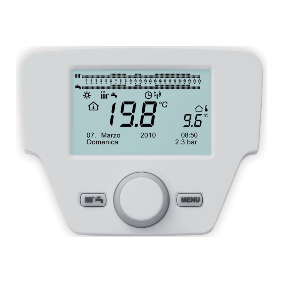
CONTROL PANEL
Description of the control panel display

Initialising the control panel
Configuration procedure before first commissioning
The first time you commission the boiler, you must carry out the following procedure (the text is in ENGLISH until the language selection request) as indicated in the sequence A-B-C in the figure below:

![]() B for 5 seconds ;
B for 5 seconds ;- an increasing value, as a percentage from 1 to 100, is displayed on the Control Panel. The data synchronisation operation requires a few minutes' wait time;
- select the language, date and time.
![]() select the language and
select the language and ![]() confirm.
confirm.
 B for 5 seconds ;
 select the language and
ACCESSING THE PARAMETER CONFIGURATION MENUS

| Display key | |
| a | Date: day, month, year |
| b | Day of the week |
| c | Boiler pressure / Heating circuit |
| d | Clock: hour and minute |
The list of configuration menus is as follows:
- Info
- Time and date
- User interface
- Hour programming(1, 2 - "Operating modes" section)
- Hour programming 3 / CC3 ("Operating modes" section)
- Hour programming 4 / DHW
- Hour programming 5
- CC circuit holidays (1,2,3 - "Time and date setting" section below)
- Heating circuit (1,2,3)
- Domestic hot water
- Instant DHW water heater (not used on this type of boiler)
- Error ("Unit locking/unlocking function" section)
- Generator diagnostic
The procedure below must be followed to acces the list of configuration menus (refer to the "Symbol description" section:
 C then
  B to choose the menu you want;
B to confirm or C to exit without saving.
Information menu
 If an anomaly occurs, the first item of data displayed is its code.
To display the boiler's information, select the «Info» menu key  to confirm.
| Boiler temperature | °C | Boiler flow-back temperature |
| Outdoor temperature | °C | Outdoor temperature |
| Min. outdoor temperature | °C | Minimum outdoor temperature value stored (with Outdoor Probe connected) |
| Max. outdoor temperature | °C | Maximum outdoor temperature value stored (with Outdoor Probe connected) |
| DHW temperature | °C | DHW temp (value read by the boiler's domestic circuit sensor) |
| Collector temperature | °C | Instant collector probe temp. (with solar installation coupling) |
| Heating circuit state (1,2,3) | On/Off" | Heating circuit operating mode (circuits: 1,2,3) |
| DHW circuit state | Load | Domestic circuit operating mode |
| Boiler state | On/Off" | Boiler operating mode |
| Solar installation state | - | Indicates the solar operation (with solar installation integration) |
| Customer service telephone | No. | xxxxxxxxxx |
Setting the date and time
To set the date and time, proceed as follows:
![]() select the menu Time and date
select the menu Time and date ![]() (Hours / minutes)
(Hours / minutes) ![]() (the hour flashes)
(the hour flashes)![]() to modify the hour
to modify the hour ![]() to confirm (the minutes flash)
to confirm (the minutes flash) ![]() to modify
to modify ![]() to confirm.
to confirm.![]() to modify 2 (Day / month) and 3 (Year) by carrying out the procedure above again.
to modify 2 (Day / month) and 3 (Year) by carrying out the procedure above again.![]() to return to the previous menu.
to return to the previous menu.
 select the menu Time and date
  (Hours / minutes)
  to return to the previous menu.
Modifying the language in user interface menu
To select the language, proceed as follows:
![]() select the menu to select the program line 20 (Langue)
select the menu to select the program line 20 (Langue) ![]()
![]() to choose the language
to choose the language ![]() to save.
to save.![]() to return to the previous menu.
to return to the previous menu.
Temporary heating temperature setting
The temperature is set by turning the B button to the right  to increase the value and to the left
  to reduce it and
  to confirm.
The temperature to be set, for the heating circuit, may be:
- Original setpoint temperature: if the control unit is installed in the boiler.
- Ambient temperature: if the control unit is attached to the wall.
FUNCTIONS ASSOCIATED WITH THE QUICK MENU KEY
Press the  key and turn
  to scroll through the following functions:
| then to change the status |
| then to force the DHW mode |
| then to activate the function selected, to modify the value and to confirm. |
- On/Off
When this function is activated, the display shows the symbol and the operation of the boiler in DHW regime and heating is deactivated (the anti-freeze protection function is activated). To start the boiler up again, repeat the procedure described above. - DHW forcing
This function is used to raise the hot water tank's temperature, if there is one, until it reaches the programmed temperature, independently of the hourly range programmed (the![]() symbol is present on the display)
symbol is present on the display) - CC1 regime
The boiler operating mode can be selected from this menu, as indicated in "Accessing the Parameter Configuration Menus" section - CC1 comfort setting
Select this menu to modify the comfort ambient temperature value. - DHW regime
Select this menu to activate (On) or deactivate (Off) the DHW production. The «Eco» function is not used for this boiler model. - DHW comfort setting
Select this menu to modify the maximum DHW temperature value.
![information]() When the DHW production is deactivated, the
When the DHW production is deactivated, the ![]() symbol disappears from the display.
symbol disappears from the display.
OPERATING MODES
Heating
The boiler has 4 heating operatingfmodes: Comfort - Reduced - Automatic - Protection.
To program one of the operating modes, proceed as follows:
From the main menu  regime to confirm.
![]() (anti clockwise)
(anti clockwise) ![]() Comfort - Reduced - Automatic - Protection
Comfort - Reduced - Automatic - Protection
![]() to confirm or
to confirm or ![]() exit without saving.
exit without saving.
 (anti clockwise)
  Comfort - Reduced - Automatic - Protection
 exit without saving.
CASE 1: the control unit is installed in the boiler
Turn the  button to set the boiler's start temperature.
OPERATING MODE DESCRIPTION
- Comfort : the heatingf is always activated (symbols displayed
![]() ).
). - Reduced : the heatingf is deactivated (symbols displayed
![]() );
); - Automatic : the heatingf depends on the hourly range programmed (symbols displayed
![]() );
); - Protection : the boiler shuts down and the anti-freeze protection is activated (symbol displayed
![]() )
)
 ).
). );
); );
); )
)CASE 2: the control unit is attached to the wall
![]() to set the ambient temperature in the room to be heated.
to set the ambient temperature in the room to be heated.
OPERATING MODE DESCRIPTION
- Comfort: the temperature in the room to be heated corresponds to the comfort temperature; the factory-set value is 20°C (symbols
![]() );
); - Reduced: the temperature in the room to be heated corresponds to the reduced temperature; the factory-set value is 16°C (symbols displayed
![]() );
); - Automatic: the temperature in the room to be heated depends on the hourly range programmed (symbols displayed
![]() );
); - Protection: the boiler switches on when the ambient temperature falls below 6°C (symbol displayed
![]() )
)
While the boiler is operating in Automatic mode, turn button B to set the temperature temporarily. This modification remains valid until the next hourly range is changed.
 The boiler's anti-freeze is always activated; the boiler starts up when the heating start temperature is under 5°C. This function is operational if the appliance is powered electrically and if there is gas.
Ambient temperature setting in reduced mode
To program the ambient temperature in Reduced mode, proceed as follows:
![]() «Heating circuit 1»
«Heating circuit 1» ![]()
![]() the programe line 712 (Reduced setpoint), then
the programe line 712 (Reduced setpoint), then ![]() (the temperature value starts to flash);
(the temperature value starts to flash);![]() to modify the temperature and
to modify the temperature and ![]() to confirm.
to confirm.![]() to return to the previous menu.
to return to the previous menu.
 to return to the previous menu.
 The comfort ambient temperature may be set not only using the A key in "Control Panel" section, but also by modifying the 710 parameter as indicated above.
Holiday program
This function enables users to choose the ambient temperature value to be programmed when they are going away for several days (for example during holidays). The minimum anti-freeze temperature or the Reduced mode temperature (program line 648) may be programmed. In program line 641 (Preselection), 8 programming levels named Period 1 (next 8 days to be programmed in on and off) are available. When the function is activated, the display shows the symbol ![]()
The following procedure activates the function and programs the hourly ranges:
![]() CC1 circuit holidays
CC1 circuit holidays![]() program line 641 («Preselection»)
program line 641 («Preselection») ![]() Period 1 (flashes) B and choose the day to program (from 1 to 8), then B program line 642.
Period 1 (flashes) B and choose the day to program (from 1 to 8), then B program line 642.![]() to program the start period (642)
to program the start period (642) ![]() to program the month
to program the month ![]() and
and ![]() to program the day
to program the day ![]() to confirm.
to confirm.- Repeat the same sequence of instructions to also program the program line 643 (at the end of the range, the boiler starts working on the next day).
- Once the start and end of the range have been programmed
![]() the program line 648
the program line 648 ![]() to program the minimum operating temperature, if anti-freeze, or Reduced mode, then
to program the minimum operating temperature, if anti-freeze, or Reduced mode, then ![]() to confirm.
to confirm. - Repeat these three points to program other ranges or
![]() to return to the previous menu.
to return to the previous menu.
 CC1 circuit holidays
 to program the month
  the program line 648
  to return to the previous menu.
PARAMETER PROGRAMMING
WE RECOMMEND THAT YOU WRITE DOWN ALL THE PARAMETERS YOU CHANGE AT THE BACK OF THIS MANUAL.

| Menu key | ||
| 1 | End user | 3 Specialist |
| 2 | Commissioning | 4 OEM |
The procedure for accessing the four menus to program the boiler is as follows:
- from the main menu
![]()
![]() A and C (hold down for around 6 seconds)
A and C (hold down for around 6 seconds)
![]() menu 1-2-3-4 (see the figure opposite and the key).
menu 1-2-3-4 (see the figure opposite and the key).![]() press several times to go back one menu at a time to the main menu.
press several times to go back one menu at a time to the main menu.

 A and C (hold down for around 6 seconds)
 menu 1-2-3-4 (see the figure opposite and the key).
HOURLY PROGRAMMING
Before accessing the programming, you must activate the Automatic operating mode (see "Accessing the Parameter Configuration Menus").
The hourly heating (CC1 hourly programming) and DHW (Hourly program 4 / DHW) programming is used to program the boiler's automatic operation during determined daily hourly ranges and during the days of the week. The example in the figure below refers to the daily hourly range 1 (below) where « a » is the operating period at comfort temperature and « b » is the operating period in Reduced mode. The boiler operating programming may be performed by groups of days or by individual days (every day from Monday to Sunday).

Preset weekly intervals
(Program line 500 for the heating and 560 for the DHW)
- Mon-Sun (groups of days)
- Mon-Fri (groups of days)
- Sat-Sun (groups of days)
- Monday-Tuesday-Wednesday-Thursday-Friday-Saturday-Sunday (individual days)
Preset daily hourly ranges
(Program line 514 for the heating and 574 for the DHW)
- 06:00-08:00.. 11:00-13:00.. 5pm - 11pm (example in the figure opposite)
- 06:00-08:00.. 5pm-11pm0
- 06:00-23:00
Groups of days
This function is used to program one of the 3 weekly intervals availabe, each with three preset daily hourly ranges to switch the boiler on and off, which may be modified by the user - program program 501...506. The intervals are the following: Mon-Sun (default value) / Mon-Fri / Sat-Sun.
If the installation is divided into zones, with each one controlled by its control unit/room thermostat, each zone must be programmed separately on each device.
Individual days
All of the daily boiler switch on/off phases may be modified by the user. For each day selected, 3 preset hourly ranges are available, as stated in the summary table at the end of this chapter.
Hourly programming modification procedure
(Heating/DHW)
After performing the hourly programming using the preset programs, you can modify the periods of the three hourly ranges - program lines 501...506 for the heating and 561...566 for the DHW, as described below.
Heating circuit programming modification procedure
![]() CC1 hourly program
CC1 hourly program ![]() program line 500 (Day selection).
program line 500 (Day selection).![]() : the groups of days field ("Time and date setting" section) starts to flash B to scroll through the days («Groups of days» or «Individual days»)
: the groups of days field ("Time and date setting" section) starts to flash B to scroll through the days («Groups of days» or «Individual days») ![]() to confirm.
to confirm.![]() program line 514 (Default value selection?)
program line 514 (Default value selection?) ![]() and
and ![]() to select one of the 3 programs preset for the daily «Groups of days» ("Parameter programming" section) programming or
to select one of the 3 programs preset for the daily «Groups of days» ("Parameter programming" section) programming or ![]() a position anto-clockwise to switch to manual programming: program lines 501....506.
a position anto-clockwise to switch to manual programming: program lines 501....506.
 program line 514 (Default value selection?)
  to select one of the 3 programs preset for the daily «Groups of days» ("Parameter programming" section) programming or
 DHW circuit programming modification procedure
The procedure to activate the hourly programming for the domestic hot water is the same as for the hourly programming for the heating. The only difference is with the name of the menu Hourly program 4 / DHW and the program lines to be programmed 560 (Day selection). To deactivate this function, you must run the procedure described below in the «Restoring the original default programming» section.
| Summary table | ||||
| Groups of days | Program line 514 (heating) - 574 (DHW) | |||
| Preset programs | Preset programs | |||
| On 1 - Off 1 | On 2 - Off 2 | On 3 - Off 3 | ||
| Mon-Sun | 06:00 - 08:00 | 11:00 - 13:00 | 17:00 - 23:00 | |
| Mon-Fri | 06:00 - 08:00 | 17:00 - 23:00 | ||
| Sat-Sun | 06:00 - 23:00 | |||
| Individual days | Prog. lines 501 502 503 504 505 506 (heating) - 561 562 563 564 565 566 (DHW) | |||
| Day interval | Preset programs | |||
| On 1 - Off 1 | On 2 - Off 2 | On 3 - Off 3 | ||
| Monday-Tuesday- Wednesday Thursday-Friday | 06:00 - 08:00 | 11:00 - 13:00 | 17:00 - 23:00 | |
To facilitate programming, the existing programs may be copied to the other days of the week. The procedure is as follows:
Copying a program to another day
After programming the hourly range for a set day, it may be copied to one or more days of the week.
The parameter in brackets « ( ) » refers to the hourly programing in DHW
- From program line 514 (574) (if one of the 3 preset hourly ranges is used) or from the program line 501(561) (if the manual programming was executed), turn the button to the right to the program line 515 (575).
- The display shows Copy?.
![]() Copy to : the day of the week flashes.
Copy to : the day of the week flashes.![]() To scroll through the days of the week, choose the day where the program is to be copied then
To scroll through the days of the week, choose the day where the program is to be copied then ![]() to confirm.
to confirm.- Repeat the point above if you want to copy the same daily program to other days.
![]() to return to the previous menu.
to return to the previous menu.
 Copy to : the day of the week flashes.
 to return to the previous menu.
Restoring the original programming (default)
The weekly programming may be deleted and the comfort heating activated (the value which will be programmed is 00-24, identical for all the days of the week).
![]() CC1 hourly program
CC1 hourly program ![]() the program line 500 (CC1 hourly program) or 560 (Hourly program 4 / DHW).
the program line 500 (CC1 hourly program) or 560 (Hourly program 4 / DHW).![]() a position anti-clockwise, the program line 516 (Default
a position anti-clockwise, the program line 516 (Default ![]() values) for the heating and program line 576 for the DHW.
values) for the heating and program line 576 for the DHW.![]() a position until Yes is displayed,
a position until Yes is displayed, ![]() to confirm.
to confirm.![]() to return to the previous menu.
to return to the previous menu.
 CC1 hourly program
  the program line 500 (CC1 hourly program) or 560 (Hourly program 4 / DHW).
 a position anti-clockwise, the program line 516 (Default
  values) for the heating and program line 576 for the DHW.
 a position until Yes is displayed,
 When the main menu is displayed once the procedure is complete, you will note that the daily programming bar changes. The heating is still active for 24 hours. To reprogram the boiler, you must repeat the procedure described in "Operating modes" section
UNIT LOCKING/UNLOCKING FUNCTION
In order to prevent unauthorised people from programming, it is possible to lock all the functions associated with the C key.
Locking procedure
![]() User interface
User interface ![]() press to confirm.
press to confirm.![]() program line 27 (Programming locking),
program line 27 (Programming locking), ![]() to confirm.
to confirm.![]() to activate the locking function.
to activate the locking function.
 User interface
  program line 27 (Programming locking),
  to activate the locking function.
Unlocking procedure
![]() A and B (hold down for approx. 6 seconds) Locking programming temporarily inact. ».
A and B (hold down for approx. 6 seconds) Locking programming temporarily inact. ».
 A and B (hold down for approx. 6 seconds) Locking programming temporarily inact. ».
This unlocking phase is temporary, it lasts 1 minute, then the unlocking is reactivated automatically. To deactivate the function permanently, you must activate the temporary unlocking procedure then  Off in the program line 27 (Programming locking) and to confirm the unlocking.
SHUTTING DOWN THE UNIT
To shut down the boiler, you must cut the electricity supply to the appliance by pressing the two-pole switch. When the «Protection mode» operation is activated, the boiler remains off but the electrical circuits are still  powered up and the anti-freeze function is activated
ERRORS
The errors on the display are identified by the  symbol, the information displayed is:

- An error code
- A secondary error code
- A brief description of the error
- The following symbols may appear on the display:
![]() their meanings are explained in the table below.
their meanings are explained in the table below.
 their meanings are explained in the table below.
If an error occurs, to display the main menu,  The symbol remains on the display to indicate that the appliance has an error; after one minute, the display shows the error page again, as indicated in the figure.
Error reset
The errors may be reset AUTOMATICALLY, MANUALLY or require the APPROVED TECHNICAL ASSISTANCE SERVICE. Below are the different commands in detail:
AUTOMATIC
If the flashing symbol  appears on teh display, the error is reset automatically (temporary error) as soon as the element which caused it stops.
Often, errors of this type are generated by water outlet/return temperatures that are too high in the boiler, then they are reset automatically as soon as the temperature falls below the critical value. If the same error is repeated frequently and/or it is not automatically restet by the boiler, contact the approved Technical Assistance Service.
MANUAL
To reset the error manually when the corresponding code appears  « Yes » to confirm. The error code disappears after a few seconds.
REQUEST FOR INTERVENTION FROM THE APPROVED TECHNICAL ASSISTANCE SERVICE
If the display shows the  symbol and the
  symbol, you must contact the APPROVED TECHNICAL ASSISTANCE SERVICE. Before calling, we recommend that you note down the code(s), error(s) and a brief description.
 If the error code displayed is not on the list or when an error occurs with a certain frequency, we recommend that you contact the APPROVED TECHNICAL ASSISTANCE SERVICE.
| Error table | |||
| (A) | (C) | (A) | (C) |
 | Error description | | Error description |
| 10 | Outdoor probe sensor | 125 | Safety disconnection due to lack of circulation (check made by a temperature sensor) |
| 20 | NTC flow-back sensor | 128 | Flame extinguishing |
| 28 | Flue gas NTC sensor | 130 | Disconnection by flue gas NTC probe for overheating |
| 40 | NTC return sensor | 133 | Ignition fault (4 attempts) |
| 50 | DHW sensor (only for heating only model with hot water tank) | 151 | Internal heating board error |
| 52 | Solar DHW sensor (for integration of a solar installation) | 152 | General configuration error |
| 73 | Solar collector sensor (for integration of a solar installation) | 160 | Fan operating error |
| 83 | Communication problem between boiler board and control unit. Probable short-circuit on the heating | 171 | ACI board fault |
| 84 | Address conflict between several control units (internal anomaly) | 321 | DHW NTC sensor damaged |
| 109 | Presence of air in the boiler circuit (temporary anomaly) | 343 | General solar installation configuration error (for integration of a solar installation) |
| 110 | Disconnection of the safety thermostat due to overheating (pump blocked or air in the heating circuit) | 384 | Incorrect light (interfering flame - internal anomaly) |
| 111 | Disconnection of the safety thermostat due to overheating | 385 | Supply voltage too low |
| 117 | Hydraulic circuit pressure too high | 386 | Fan speed threshold not reached |
| 118 | Hydraulic circuit pressure too low | 430 | Safety disconnection due to lack of circulation (check made by a pressure sensor) |
SPECIAL FUNCTIONS

The functions available are:
- Manual regime (301) - Options: 25 - 90 (°C) When this function is activated, the boiler runs on heating according to the temperature setpoint value.
- Sweeping function (303) - Options: Total load (max thermal power of the boiler), Partial load (reduced thermal power), Total heating load (maximum thermal power in heating function).
- Regulator shutdown function (304) - Options: from 100% (maximum thermal power) to 0% (reduced thermal power). Activate this function to facilitate the gas valve calibration operations.
- Drain function (312) - Options: On (function activation) - Off (function exit). See chapter "Installation drain function"
The procedure to follow to activate these functions is
- From the main menu
![]() A and C (hold down for approx. 6 seconds)
A and C (hold down for approx. 6 seconds) ![]() names of FUNCTIONS (see the figure opposite: 301 - 303 - 304 - 312)
names of FUNCTIONS (see the figure opposite: 301 - 303 - 304 - 312) ![]() to select the FUNCTION
to select the FUNCTION ![]() to ACTIVATE the selected function then
to ACTIVATE the selected function then ![]() menu in the FUNCTION
menu in the FUNCTION ![]() to modify (see the example below).
to modify (see the example below).
 A and C (hold down for approx. 6 seconds)
  names of FUNCTIONS (see the figure opposite: 301 - 303 - 304 - 312)
 to select the FUNCTION
  menu in the FUNCTION
  to modify (see the example below).
Example: turn button B to activate the CALIBRATION function (program line 304), press button B, the function is now operational and preset to 100 % (the boiler reaches the maximum thermal power). Press the button and turn it to set the desired power level as a percentage (0% corresponds to the reduced thermal power)
To interrupt the function manually, repeat the procedure described above, when the function deactivated the display shows «Off».
Drain function
This function is used to facilitate the elimination of air inside the heating circuit when the boiler is installed or after primary circuit water drainage maintenance operations. The electronic board will activate an on/off cycle for the pump lasting 10 minutes. The function will stop automatically at the end of the cycle.
To interrupt the function manually, repeat the procedure described above, when the function is deactivated the display shows «Off».
ADJUSTMENT AND SAFETY DEVICES
This unit is designed in accordance with European standards and directives and in particular with the following elements:
- Safety thermostat
A safety thermostat turns off the boiler if the water temperature is too high in the primary circuit. It is imperative to find the cause of overheating before resetting.
IT IS FORBIDDEN TO DEACTIVATE THIS SAFETY DEVICE - NTC flue gas sensor
This device is placed on the water-exchanger flue gas.
The electronic card on the control panel turns off the boiler if the temperature exceeds 110°C.
NB: the reset operation is only possible if the temperature is below 90°C.
IT IS FORBIDDEN TO DEACTIVATE THIS SAFETY DEVICE - Flame ionisation electrode
The flame detection electrode guarantees safety in the event of gas starvation or poor burner ignition. In this case it turns off the boiler. - Hydraulic pressure controller
This device allows the burner to start only if the water pressure is above 0.5 bar. - Heating circulator with post-circulation
The electronic control allows the heating pump a post-circulation of 3 minutes after the burner shuts down in heating mode if the room thermostat calls for the burner stop. - Antifreeze protection
The boiler's electronic control system included in heating mode or domestic hot Sanitary water production has a protection against frost. If the water temperature falls below 6°C the burner starts up to reach a temperature of 30°C. This function is only valid if the boiler is lit, gas is open, and water pressure is correct. - Circulator blockage protection
If no request for heating or domestic hot water is received for 24 hours, the circulator starts automatically for 10 seconds to avoid any blockage. - Blockage protection in 3-way valve
If no heating demand is received for 24 hours, the 3-way valve automatically performs a complete operating cycle. - Safety valve (heating circuit)
This device limits the pressure in the heating circuit to 3 bar.
Do not use to drain the heating circuit. - Heating circulator with pre-circulation
In the case of a heat request in heating mode, the unit can operate the circulator in pre-circulation before lighting the burner. This pre-circulation phase may last a few minutes depending on the operating temperature and the installation conditions.
SERVICING
![warning]() The boiler must be serviced and cleaned at least once per year by a qualified professional.
The boiler must be serviced and cleaned at least once per year by a qualified professional.
The annual servicing must be carried out in accordance with the decree of 15th September 2009 relative to the annual servicing of boilers whose nominal power is between 4 and 400 kW. The professional must deliver a certificate to the end user.
- Sweep out at least once per year, or more depending on current regulations.
- All the maintenance operations must be carried out by a qualified professional.
- We recommend subscribing to a servicing contract.
- Only original spare parts must be used.
- Do not clean the casing with abrasive and/or easily-flammable products (e.g. petrol, alcohol, etc.). Always disconnect the unit's electrical power supply before cleaning it.
TECHNICAL SPECIFICATIONS
ErP technical parameters
| BAXI - Power | 1.32 | 32 Combi 160 | 32 Solar 220 | ||
| Condensing boiler | Yes | Yes | Yes | ||
| Low-temperature boiler(1) | No | No | No | ||
| B1 boiler | No | No | No | ||
| Cogeneration space heater | No | No | No | ||
| Combination heater | No | Yes | Yes | ||
| Rated heat output | Prated | kW | 32 | 32 | 32 |
| Useful heat output at rated heat output and high temperature regime(2) | P4 | kW | 32 | 32 | 32 |
| Useful heat output at 30% of rated heat output and low temperature regime(1) | P1 | kW | 5,5 | 5,5 | 5,5 |
| Seasonal space heating energy efficiency | ηs | % | 92 | 92 | 92 |
| Useful efficiency at rated heat output and high temperature regime(2) | η4 | % | 87,9 | 87,9 | 87,9 |
| Useful efficiency at 30% of rated heat output and low temperature regime(1) | η1 | % | 97,3 | 97,3 | 97,3 |
| Auxiliary electricity consumption | |||||
| Full load | elmax | kW | 0,075 | 0,075 | 0,075 |
| Part load | elmin | kW | 0,015 | 0,015 | 0,015 |
| Standby mode | PSB | kW | 0,004 | 0,004 | 0,004 |
| Other items | |||||
| Standby heat loss | Pstby | kW | 0,081 | 0,081 | 0,081 |
| Ignition burner power consumption | Pign | kW | - | - | - |
| Annual energy consumption | QHE | GJ | 100 | 100 | 100 |
| Sound power level, indoors | LWA | dB | 56 | 56 | 56 |
| Emissions of nitrogen oxides | NOx | mg/kWh | 28 | 28 | 28 |
| Domestic hot water parameters | |||||
| Declared load profile | XL | XL | |||
| Daily electricity consumption | Qelec | kWh | 0,287 | 0,317 | |
| Annual electricity consumption | AEC | kWh | 63 | 70 | |
| Water heating energy efficiency | ηwh | % | 82 | 83 | |
| Daily fuel consumption | Qfuel | kWh | 23,681 | 23,105 | |
| Annual fuel consumption | AFC | GJ | 18 | 18 | |
| (1) Low temperature means for condensing boilers 30°C, for low temperature boilers 37°C and for other heaters 50°C return temperature (at heater inlet). (2) High temperature regime means 60°C return temperature at heater inlet and 80°C feed temperature at heater outlet. | |||||
ErP information
Product fiche
| BAXI - Power | 1.32 | 32 Combi 160 | 32 Solar 220 | |
| Space heating - Temperature application | Medium | Medium | Medium | |
| Water heating - Declared load profile | XL | XL | ||
| Seasonal space heating energy efficiency class |  | |  | |
| Water heating energy efficiency class |  |  | ||
| Rated heat output (Prated or Psup) | kW | 32 | 32 | 32 |
| Space heating - Annual energy consumption | GJ | 100 | 100 | 100 |
| Space heating - Annual energy consumption | kWh(1) GJ(2) | 63 18 | 70 18 | |
| Seasonal space heating energy efficiency | % | 92 | 92 | 92 |
| Water heating energy efficiency | % | 82 | 83 | |
| Sound power level LWA Indoors | dB | 56 | 56 | 56 |
| (1) Electricity (2) Fuel | ||||
Package fiche

The energy ef ciency of the package of products provided for in this che may not correspond to its actual energy ef ciency once installed in a building, as this efficiency is influenced by further factors such as heat loss in the distribution system and the dimensioning of the products in relation to building size and characteristics.
- The value of the seasonal space heating energy efficiency of the preferential space heater, expressed in %.
- The factor for weighting the heat output of preferential and supplementary heaters of a package as set out in the following table.
| Psup / (Prated + Psup)(1)(2) | II, package without hot water storage tank | II, package with hot water storage tank |
| 0 | 0 | 0 |
| 0,1 | 0,30 | 0,37 |
| 0,2 | 0,55 | 0,70 |
| 0,3 | 0,75 | 0,85 |
| 0,4 | 0,85 | 0,94 |
| 0,5 | 0,95 | 0,98 |
| 0,6 | 0,98 | 1,00 |
| > 0,7 | 1,00 | 1,00 |
| (1) The intermediate values are calculated by linear interpolation betw een the two adjacent values. (2) Prated is related to the preferential space heater or combination heater. | ||
- The value of the mathematical expression: 294/(11xPrated), whereby Prated is related to the preferential space heater.
- The value of the mathematical expression 115/(11 Prated), whereby Prated is related to the preferential space heater.
SAFETY INSTRUCTIONS
General safety instructions

If any smoke is given off:
- Switch off the unit.
- Open the windows.
- Call a qualified professional to search for the probable leak and correct it immediately.

Do not touch the flue gas ducts. Depending on the unit's settings, the flue gas duct temperature may exceed 60°C.
Do not touch the radiators for any lengthy periods of time. Depending on the unit's settings, the radiator temperature may reach 85°C.
Be careful with domestic hot water. Depending on the unit's settings, the domestic hot water temperature may reach 65°C.

Do not leave the unit without servicing. Contact a qualified professional or subscribe to a maintenance contract for the unit's annual servicing.
This unit is not intended to be used by people (including children) whose physical, sensory or mental capacities are reduced or by people who do not have any experience or knowledge of the unit, unless they are monitored or have been provided with prior instructions on the use of the unit by someone who is responsible for their safety. Children should be supervised to ensure they do not play with the unit.
Recommendations
Only qualified professionals are authorised to work on the unit and the installation.
Comment
Check regularly that the installation is full of water and under pressure (minimum pressure 0.5 bars, recommended pressure between 1.5 and 2.0 bars).
Comment
Ensure that the unit is accessible at all times.
Comment
Never remove or cover the information labels and plates on the unit. The information plates and labels must be legible for the unit's full lifetime.
Do not store explosive or easily-flammable materials in the boiler room or near the boiler, even temporarily.
Use Antifreeze mode rather than power down the unit to carry out the following functions:
- Pump sticking release
- Antifreeze protection
- ACI function (depending on version)
Specific safety instructions
This unit has been designed according to European standards and directives and in particular is equipped with the following elements:
- Safety thermostat
A safety thermostat turns off the boiler if the water temperature is too high in the primary circuit. It is imperative to find the cause of overheating before resetting. Contact your installer.
It is forbidden to deactivate this safety device.
- NTC flue gas sensor
This device is placed on the water-exchanger flue gas.
The electronic card on the control panel turns off the boiler if the temperature exceeds 90°C.
The MMI indicates that the flue gas temperature has been exceeded. Switch off the boiler. It is imperative that you find the cause before restarting it. Contact your installer. - Flame ionisation electrode
The flame detection electrode guarantees safety in the event of gas disconnection or poor burner ignition. In this case it turns off the boiler. - Hydraulic pressure controller
This device allows the burner to start only if the water pressure is above 0.5 bars. - Heating circulator with post-circulation
The electronic control allows the heating pump a post-circulation of 3 minutes after stopping the burner in heating mode if the room thermostat calls for the burner to stop. - Antifreeze protection
The boiler's electronic control system included in heating mode or domestic hot water production has a protection against frost. If the water temperature falls below 6°C the burner starts working to reach a temperature of 30°C. This function is only valid if the boiler is lit, gas is open, and water pressure is correct. - Circulator blockage protection
If no request for heating or domestic hot water is received for 24 hours, the circulator starts automatically for 10 seconds to avoid any blockage. - Blockage protection in 3-way valve
If no heating demand is received for 24 hours, the 3-way valve automatically performs a complete operating cycle. - Safety valve (heating circuit)
This device limits the pressure in the heating circuit to 3 bars.
Do not use to drain the heating circuit. - Heating circulator with pre-circulation
In the case of heat in heating mode, the unit can operate the pre-circulation pump before lighting the burner. This precirculation phase may last a few minutes depending on the operating temperature and the installation conditions.
36061 Bassano del Grappa (VI) - ITALIA
Via Trozzetti, 20
Customer service: tel. +39 0424-517800 – Telefax +39 0424-38089
www.baxi.it
Documents / Resources
References
Download manual
Here you can download full pdf version of manual, it may contain additional safety instructions, warranty information, FCC rules, etc.
Advertisement


Need help?
Do you have a question about the Power and is the answer not in the manual?
Questions and answers