Abus PR2700, PR2700B - Reinforced Door Bar Manual
- Fitting and operating instructions (68 pages) ,
- Fitting and operating instructions (33 pages) ,
- Fitting and operating instructions (33 pages)
Advertisement
- 1 Introduction
- 2 Package contents of the PR2700 in a standard design
- 3 Field of application of the PR2700
- 4 Fitting tools
- 5 Replacing the door cylinder (optional)
- 6 Fitting instructions for doors that open inwards
- 7 Operating instructions
- 8 ABUS special accessories
- 9 Assembly
- 10 Operation
- 11 Documents / Resources
Introduction
The ABUS reinforced door bar provides additional protection against unauthorised break-ins into rooms. It is suitable for all standard doors made of wood, metal and plastic. Not all varieties of use for the PR2700 can be adressed with these fitting instructions. Ask a dealer if necessary. The optimal protective effect is reached if you proceed according to these fitting and operating instructions. The mounting screws should be tightened manually with a suitable tool to avoid overwinding. Prior to fitting, you should ensure that the reinforced door bar is suitable for the structural circumstances. The manufacturer disclaims all liability for any injury or damage caused during fitting and/or by improper handling!
We recommend allowing a specially trained specialist installer to execute the fitting.
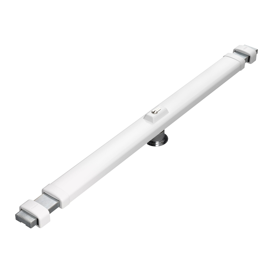
Package contents of the PR2700 in a standard design
(Fig. 1)

Field of application of the PR2700
The PR2700 is suitable for all hinged and unhinged doors that open inwards and outwards, DIN right or DIN left (Fig. 2). Doors with panelling and/or border trimmings must be individually adjusted.

The standard design is suitable for doors opening inwards (door panel width of 735 mm to 1030 mm and door panel thicknesses of 35 to 50 mm).
For doors opening outwards or thick doors, special accessories are available commercially.
The PR2700 can be fitted with a knob cylinder or a door half-cylinder (without the possibility of closing from the outside).
The PR2700 can also be equipped with different door cylinders following EN DIN 1303 / DIN 18252.
VdS recognition
The VdS recognition only applies in connection with the use of a VdS class A or a higher class of door cylinder. The reinforced door bar PR2700 with VdS recognition is registered under the number M 110318 VdS.
We recommend fitting beneath the mounting (Fig. 3).

Fig. 3
The fitting of 2 pieces PR2700 is recommended in the event of increased safety require ments. One is then fitted above and below the mounting (Fig. 4).

Fig. 4
The closing direction can be adjusted according to the door lock.
Fitting tools
- Phillips screwdriver
- Drilling machine for wood, metal and walls
- Metal drill:
(also use with wood)
Ø 3,0 mm
Ø 3,5 mm
Ø 5,0 mm
Ø 8,5 mm
Ø 10,0 mm - Masonry drill bit:
Ø 10,0 mm, length of at least 160 mm, as good as new
Ø 6,0 mm
Ø 16,0 mm, for a wall lock - Milling cutter/hole saw: Ø 51–55 mm
- Mechanic's level, metering rule
- Hexagon socket screw key SW 3, SW 4, SW 5
- Metal saw, file
- Tools for additional work are not included in this installation
Replacing the door cylinder (optional)
If the door cylinder does not need to be replaced, continue to read under Fitting tools chapter.

The VdS recognition only applies in connection with the use of a VdS class A or a higher class of door cylinder.
With door leaf strengths above 50 mm and/or if the door cylinder has to fit in a locking system, the standard door cylinder must be replaced.
The same applies if it is set to be fitted without any "option to lock from outside".
- New door cylinders correspond to DIN EN 1303/DIN 18252 and obtain spacers and longer screws if required:
- With door leaf strengths greater than 50 mm: Obtain door cylinders of a greater length (see tab 1), as well as spacer and longer screws if required
- Use the door half-cylinder 10/30 during fitting without the possibility of closing from the outside
Table 1
| Door panel thickness in mm | Cylinder dimensions | Spacer disc DS05 PR 5 mm (Item no. 24363) | Spacer disc DS10 PR 10 mm (Item no. 4623) | Screws DIN 7984-8.8. in mm |
| 35 - 50 | 30/60 | - | - | M6 x 45 (enclosed) |
| 51 - 55 | 30/65 | 1 | - | M6 x 45 (enclosed) |
| 56 - 60 | 30/70 | - | 1 | M6 x 45 (enclosed) |
| 61 - 65 | 30/75 | 1 | 1 | M6 x 45 (enclosed) |
| 66 - 70 | 30/80 | - | 2 | M6 x 45 (enclosed) |
| 71 - 75 | 30/85 | 1 | 2 | M6 x 60 (Item no 1685) |
| 76 - 80 | 30/90 | - | 3 | M6 x 60 (Item no 1685) |
| 81 - 85 | 30/95 | 1 | 3 | M6 x 60 (Item no 1685) |
| 86 - 90 | 30/100 | - | 4 | M6 x 60 (Item no 1685) |
| 91 - 95 | 30/105 | 1 | 4 | M6 x 80 (Item no 1686) |
| 96 - 100 | 30/110 | - | 5 | M6 x 80 (Item no 1686) |
| 101 - 105 | 30/115 | 1 | 5 | M6 x 80 (Item no 1686) |
| 106 - 110 | 30/120 | - | 6 | M6 x 80 (Item no 1686) |
- Lock door bars and remove the door cylinder in the specified order according to Fig. 5.

- Change the grub screw and the gear-wheels clip of the standard door cylinder to the new door cylinder, according to Fig. 5. The grub screw must protrude at the same distance on both sides.If the cylinder length does not change, continue to point 8.
- Unscrew the loosened screw 1 (Fig. 6), move the gear-wheel housing in the direction of the arrow. Unscrew the cylinder protection's screws located beneath (Fig. 6).

- Remove the cylinder protection according to Fig. 7 and place additional spacer disc/s (Tab. 1.) between the cylinder protection and the lock body. Tighten with screws (Tab. 1).

- Pull the gear-wheel housing into the old fitting position again (Fig. 6) and fix loosely with screw 1.
- Push toothed gear racks in the direction of the arrow (fig. 8) until they stop, whereby the upper ones must be pushed back by one tooth.
- Reinstall the door cylinder in the reverse order (Fig. 5). If the indentations do not correspond, loosen the stop screws 6. and 7. (Fig. 8), pull both door bars out until the gear-wheels do correspond and complete the installation of the door cylinder. Set the key pull-off position (see the instructions below).


 Notes on setting the key removal positions:
For each turn of the key the bolts move 80 mm. If the available space is less than 160 mm, the security door bar can only be locked with one turn.
For single-turn locking: Lock the bolt by turning the key twice. Unscrew the adjusting stop screw 6. (Fig. 8), hold the stop slide, re-close the bolt one turn, remove the key. Push the stop slide in the direction of the arrow as far as it will go, tighten the stop screw.


Do not overwind.
Setting the first key removal position: Bolts are locked, key has been removed. With the adjusting stop screw 6. loosened (Fig. 8), push the stop slide in the direction of the arrow as far as it will go, tighten the stop screw.
Do not overwind.
Setting the second key removal position (only required when using the door guard, optional accessory PSB2700: Lock the bolt by turning the key twice and remove the key. With the stop screw 7. loosened (Fig. 8), push the stop slide in the direction of the arrow as far as it will go, tighten the stop screw.
Do not overwind.
Fitting instructions for doors that open inwards
Before mounting, please check the setting of the door and adjust it optimally if necessary. If the door opens outwards, please use the mounting set, accessory PA1018.
Before proceeding with the following mounting steps, please check that the PR2700 will fit on the door panel for bolts that lock with two turns of the key. In narrow niche areas, have the bolt embedded directly in the masonry, possibly using accessory PWA2700.
If the PR2700 can or must be used by closing with a single turn, the key removal position must be set prior to mounting the lock body (see note above).
Preliminary remarks:
- Make sure the substrate is stable and there are good mounting options. It is particularly advisable to anchor the lock casing to the masonry and to mount it as close as possible to the edge of the door, taking the stable substrate into account.
- For narrow doors, single-turn closing may be sufficient (see Replacing the door cylinder Chap., 8).
- The bolts should project approx. 10 mm (Fig. 15) from the lock casing.

- Even out the folding thicknesses with plastic washers (Fig. 16).

- Do not allow the lock body to collide with the lock casing on the hinge side (Fig. 17; if necessary, fit a separate door stopper).


Fitting the lock body
- Set and mark the position of the lock body on the door panel (Fig. 3+4).
- Mark the cylinder hole Ø 51-55 mm in the centre of the lock body as shown in Fig. 9. To check that all the measured dimensions actually fit, place the security door bar on the cylinder hole. Make any corrections and then drill the hole from both sides using a floor in front of the markings on the door and lock it out with the key before drilling the keyhole cutter/saw.

Before fitting the lock body, remove the cover hood corresponding to Fig. 10. - Mount the lock body, attach the escutcheon at door exterior (Fig. 11).

- Position lock body corresponding to Fig. 12.


Mark the position of the fastening screws through the mounted lock body.
Then turn the lock body on the cylinder rosette to the vertical position and pre-drill the screw holes (wood Ø 3.0 mm/metal Ø 3.5 mm). Fasten the lock body in place with screws Ø 4.2 x 22 mm.
Note: With cavity doors, pre-drill Ø 6mm, use supplied bridging cartridge and tighten with Ø 4 x 35 mm screws corresponding to Fig. 13.

Do not overwind.
Changing the closing direction to DIN right opening doors (delivery state: DIN left opening door)
Close the door bar until the door bar adjusting screw is accessible in the first window and corresponds in height to the screw hole on the opposite side (Fig. 14). Unscrew the screws and retighten the opposite ones in each case.

Lock case fitting and setting the door bar length
Close the door bar and remove the key. Attach the lock case to the door bar (Fig. 15). If there is no suitable attachment point, loosen the door bar adjusting screw (1.) according to Fig. 16 and move the door bar casing until such time as a suitable mounting point is reached. Mark the lock case position.
- Close the door, hold the cover onto the lock body and first mark and make a cut of 3-15 mm on both sides according to the door frame width, z. B. with a metal saw (Fig. 18).

- Press down the door bar guides and secure with 2 screws 3.5 x 6.5 mm (Fig. 19).

![]()
Do not overwind.


- Press down the cover onto the lock body (Fig. 20).


Attaching the lock cases
Close the door bar, put the lock cases with screw-on plate and plastic underlays underneath according to the rebate height, hold onto the marked fitting position, align vertically in the centre of the door bar and mark out. Close the door bar (Fig. 15).
Fitting with screw-on plates
Pay attention to the correct location of the screw-on plate: the slope of the fixing holes in the wall must be pointed away from each door edge, when looking in the drilling direction (Fig. 21).

- Hold the screw-on plate onto the marked lock case position without the lock case, predrill the positions for 2 screws Ø 4 x 35 mm for dowel and wood (dowel Ø 6 mm, wood Ø 3 mm), Ø 4.2 x 22 mm for metal Ø 3.5 mm. Tighten the screw-on plate with 2 screws (Fig. 21).
- For further reinforcement, fit wooden screws with Ø 7 x 60 mm or dowels with Ø 10 x 120 mm: For this purpose: bore two bevelled holes with Ø 5 mm and a depth of at least 60 mm for the wooden screws or with Ø 10 mm and a depth of at least 140 mm through the screw-on plate. Screw in the wooden screw or insert screw into the dowel (fig. 22), push both into the dowel hole up to the dowel collar and tighten the screw firmly.

- Drill out both holes for the lock case mount: with Ø 7 mm in wood and metal, with Ø 6 mm in stone, and a depth of at least 50 mm (Fig. 21).
- Line the screw-on plate with defined plastic underlays and tighten the lock case with two thread rolling screws M8 x 60 mm. If the screws M8 x 60 cannot be screwed in deep enough, please shorten the screws.

If the screws cannot find a secure grip, we recommend the use of composite mortar from well-known brands in connection with a cylinder screw with hexagon socket and low profile head DIN 7984-M 8 x 120 – 8.8 or longer.
Fitting with or without plastic underlays
- Hold the lock case with the defined plastic underlay onto the marked lock case position.
For flush doors and folding thicknesses < 5 mm on the mounting position, drill holes Ø 20 mm 6 mm deep so that the lock casings can be mounted flat. Drill through the two Ø 10 mm mounting holes, min. 140 mm deep for 120 mm frame plugs.
Insert the screw in the dowel (Fig. 21), push both into the hole up to the dowel collar and tighten the screw.
For special installation conditions, e.g. thicker walls, use dowels and screws with a length of 140 mm (available as special accessories from ABUS. In this case, drill the hole at least 160 mm deep).
If the screws or the dowels cannot find a secure grip, we recommend all-through screw fittings with PV1820 (Fig. 23) or the use of composite mortar from well-known brands in connection with the enclosed screw (without dowel).

- Press down the cover onto the lock cases (Fig. 24).

- Press the cylinder escutcheon firmly onto the door exterior (Fig. 25).

- The door bar can also be incorporated into the wall instead of fitting the lock case. In this case, the cover for the hole in the wall PWA2700 (Fig. 26 - 28) can be used.


Operating instructions
- Close the door initially with the existing closing safety device. Then activate the reinforced door barPR2700 as additional protection using the key. Close the door bar until the end stop by turning the key once or twice.
- The PR2700 must be retracted the other way around until the end stop before opening the door.
- The reinforced door barPR2700 is maintenance-free and does not require any lubricant. Do not use any aggressive or abrasive cleaning products when cleaning the surfaces.
ABUS special accessories
The following special accessories are commercially available to complement this security door bar for various applications:
PWA2700: Wall strike plate, instead of the normal lock casing
![information]() Note: An embrasure breadth of at least 86 cm is required for embedding into the wall on both sides (doorway 90 cm).
Note: An embrasure breadth of at least 86 cm is required for embedding into the wall on both sides (doorway 90 cm).- When using the PWA2700, first remove the plastic plug from the door bar casing (if necessary lever through the small hole with a screwdriver / Fig. 26).
- Insert the door bar end piece with round bolts and tighten with the screw of accessory article PWA2700 (Fig. 27).
- Mount the wall strike plate onto the round bolts.
- Lock the door bar onto the wall until the end stop. Mark out the attachment points (1.) of the wall strike plate. Close back the door bar (Fig. 28).
- Pre-drill the attachment points for the wall strike plate with Ø 6 mm, insert the dowel and screw (Fig. 28).
- Drill through both of the external mounting holes (2.) with Ø 10 mm, and a depth of at least 160 mm. Insert screw into the dowel (fig. 21) and tighten the screw firmly (Fig. 28).
- Drill out the holes for the connecting bolts (3.) with Ø 14 - 16 mm, width a depth of 70 mm (Fig. 28). Press down the plastic cover.
PV1820: Frame through-bolting of the lock casings in case of unstable mounting options (e.g. thin lightweight construction walls)
Mounting (use longer M8 screws if necessary):
- Drill through holes Ø 9 mm in the corresponding position through the door frame. Drill out from the outside Ø 13 mm and 35 mm deep.
- Insert the threaded sleeve including the metal plates into the screw holes from the outside as shown in the illustration (Fig. 29) and screw it together through the lock casing from the inside (use washers if necessary). Shorten the screws if necessary.
- Press the cover on from the outside.


PA1018N: Mounting set for outward opening doors
Note: Screw connection suitable for door thicknesses of 38 to 80 mm.
Drill through holes ø 9 mm, in the corresponding position through the door panel and drill out ø 13 mm and 35 mm deep from the outside.
Insert the screw sleeves including the metal plates into the screw holes from the outside as shown in the illustration (Fig. 30) and screw together through the security door bar from the inside. Shorten the screws if necessary.
Press the cover on from the outside.

PSB2700: Door guard unit for opening the door a crack
Assembly
Note:
Until the lock casing is assembled on the lock side, the assembly instructions for the PR2700 apply. Please check in advance whether there is enough space for the complete lock casing. The bar overhang from the lock casing of the lock for two-turn closing is approx. 47 mm.
Installing the lock casing on the lock side.
Replace lock tube insert:
- When using PSB2700, first remove the plastic plug from the lock tube (if necessary, use a screwdriver to lever it through the small hole / Fig. 31).

Insert the bolt end cap for door guard function and tighten all the way with self-tapping screw 5 x 12 GB from the PSB2700 set.
Drill out the cross-head of the screw with an HSS drill bit Ø 4 mm (Fig. 32) and apply e.g. a touch-up stick or lubricant to the outline of the hole (to protect from corrosion).


Installing the lock casing:
- The lock casing is pre-mounted for DIN right opening doors. For DIN left opening doors, the door guard will need to be shifted accordingly (Fig. 33).

- Lock the bolt by turning the key once and remove the key (door guard position). Loosen bolt clamping screw 1. (Fig. 34) and slide the lock tube until a suitable mounting point for the lock casing has been reached. Make sure there is a stable surface for screwing. Even out the folding thickness with mounting plate and plastic washers, if necessary. For folding thicknesses < 16 mm, we recommend using the lock body support. Mark the lock casing position. Tighten the door bar adjusting screw 1. (Fig. 34).

- For mounting the lock casing see „Mounting the lock casing with mounting plate". Then knock the safety plugs into the hexagon socket of the screws. (Fig. 35).


Operation
- Close the bolt on the reinforced door bar lock until it is in locked position. The door can now be opened in locked position. In locked position, the door guard will latch under its own weight. The door guard must be raised in order to unlock it
- The door guard unit is maintenance free. Do not use aggressive or caustic cleaning agents to clean the surface.
ASP17:
The ASP17 mounting plate is suitable for the sturdy fixing of lock casings. It is used, in particular, when the options for anchoring the reinforced door bar lock casings directly and securely to the subsurface are inadequate (Fig. 36-38).

- Establish the position of the lock casings and thus of the mounting plate in accordance with the relevant PR fitting instructions.
![information]() Note: pay attention to position – angled position of the plugs in relation to the masonry.
Note: pay attention to position – angled position of the plugs in relation to the masonry. - For basic fitting, attach the mounting plate with screws (E) and, if necessary, plugs (G) in the holes (2) as an option.
- Also fix the mounting plate with the long-shaft fixing (C) through the angled holes (3).
- If the hold is not adequate, the mounting plate can also be anchored with a combination of M8 threaded rods through the two holes (4) and injection mortar (not supplied).
- As an option, additional longer long-shaft fixings (C, not supplied) can be used for anchoring through the central hole (3).
- Fit cover (A).
- Provide the lock casings of the reinforced door bar with appropriate supports and screw in place in the required position (fix with 2 self tapping screws (D). If the rebate height is too small, it may be necessary to use a lock body support.
Underlay for the lock body
The lock body underlay allows for a more favourable assembly position of the wall cover plates to be achieved, as these can be mounted in a more stable area of the door frame / wall as a result (Fig. 39-41).

Note: to determine the cylinder length required (table 1), the underlay thickness of 18 mm must be added to the existing thickness of the door leaf.
NRS PR-Alarm:
Equipment kit for an alarm function of the reinforced door bar (Fig. 42).
Simple retrofit by replacing the lock casing caps.

Sounds at 110 decibels → see separate instructions enclosed with the product.

ABUS August Bremicker Söhne KG | D 58292 Wetter | Germany
Tel.: +49 (0) 23 35 63 40 |
UK-Importer: ABUS (UK) Ltd.
Unit 8 Third Way Corner, Avonmouth
Bristol BS11 9HL, UK
Tel.: +44 117 204 70 00 | info@abus-uk.com
Documents / Resources
References
Download manual
Here you can download full pdf version of manual, it may contain additional safety instructions, warranty information, FCC rules, etc.
Advertisement


Need help?
Do you have a question about the PR2700 and is the answer not in the manual?
Questions and answers