Advertisement
Warnings and notes in this manual
 NOTE:
NOTE:
Notes provide important information for the correct usage of the equipment. If the notes are not observed, a malfunction of the equipment is possible.

Warnings provide very important information for the correct usage of the equipment. Not observing the warnings may lead to danger for the equipment and to danger for health and life of the user.
General Information
Features
The ECO pulse amplifiers are available with different taps and output configurations.
ECO is the amplifier generation from KEM that replaces all previous versions and variants. The possible configurations include one or two channels as well as digital and analog outputs. An integrated medium temperature measurement is included as standard.
The ECO family is compatible with all KEM flow meters.
ECO pulse amplifiers can be linearized with up to 20 points.
Safety
General Safety
- As protection against fire, the supply must be protected with a fuse whose value is not higher than the permissible cable current.
- The electrical supply must be provided with a "safe extra-low voltage" (SELV).
NOTE:
- To comply with the protection class, the plug connector must be sealed with the corresponding counterpart (adequate IP rating). The protective cover supplied does not fulfill the protection class. To maintain the protection class, the housing must not be opened.
- All statements in this manual regarding safety and technical data only apply if the appliance is operated correctly in accordance with the manual.
- Shielded cables must be used for all connections to the load and the electrical supply.
- The device may only be connected and operated by authorized and sufficiently qualified personnel.
- National and international installation regulations must be observed
Special Requirements for Ex Installations
Explosion hazard
- The technical specifications in the document "T100 Control drawing for hazardous areas" must be observed.
- When used in potentially explosive atmospheres, the ECO must be operated via suitable isolating amplifiers or ten barriers.
- To avoid a possible ignition hazard, the versions with aluminum housing must not be exposed to shocks or friction from other components.
NOTE:
- The installation of the ECO in potentially explosive atmospheres must be carried out by appropriately trained personnel.
- If the installation is not carried out in accordance with the manufacturer's specifications, the safety for the corresponding type of protection is invalidated.
- When using long connecting cables, ensure that the maximum capacities and inductances for the corresponding voltage and gas group are not exceeded.
- If the housing of the ECO is opened by unauthorized personnel, the safety for the corresponding ignition protection type is void.
- Repairs may only be carried out by the manufacturer
Order designations and accessories
Ordering Code

Additional conditions for North American CSA certification:
Only ECOs with product code T*10 and an M12 stainless steel plug, can be used as Type 3 for outdoor use. All other configurations may only be used indoors.
Getting started
Unpacking
Verify that you have received the following items:
When you ordered ECO:
- ECO
- User's manual
- Conformation declaration (EU)
- T100 Control drawing for hazardous areas (ECO-Ex)
Ordering Elements
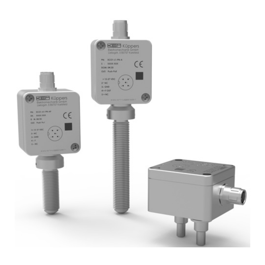
ECO

Fig. 1: ECO controls
1 = Connector plug
2 = Sensor tip
3 = Screw tap M14 thread
4 = Pickup tip
PIN Assignments
ECO

- Vcc / Loop+ (24 V)
- Digital Output 2 / NAMUR
- GND / Loop-
- Digital Output 2 / NAMUR
- Active Analog Output
Installation
Mechanical Installation
Depending on the version of the tap, the installation is performed differently.
NOTE:
Too much force will damage the sensor tip!
Plug tap
Place Position the ECO so that the tapped holes in the sensor and the insertion tips match. Screw the ECO onto the sensor hand-tight using the hexagon socket screws (width across flats 3 mm) already inserted in the housing.
NOTE:
Too much force will damage the sensor tip!
Turn the ECO back by 15°.
Fix the ECO with the lock nut on the sensor tip.
Electrical Installation
NOTE:
For connecting, shielded cables must be used. The ECO housing is connected to the cable shield.
NOTE:
Improper grounding and shielding may lead to bad EMC behavior or danger to your health!
Connect the ECO via a shielded cable to the control unit. The ECO requires a regulated DC power supply of 24 V nominal and works properly over a supply range of 12 V to 28 V.
NOTE:
Make sure that all cable and wires are connected and fixed properly before applying power to the ECO.
For the electrical connections refer to the drawings in Normal Operation chapter.
Ex Installation
The ECO... -Ex are only intrinsically safe if they are operated via isolating amplifiers or supply isolators. The technical specifications in the document "T100 Control drawing for hazardous areas" must be observedT100 must be observed
For mechanical installation, follow the installation instructions in Mechanical Installation chapter.
Connect the ECO to isolating amplifiers using a shielded cable.
Auswahl Barrieren
| Description | Manufacturer | Part Number |
| Zener Barrier 1-channel | Pepperl+Fuchs | Z728 |
| Zener Barrier 1-channel | Stahl | 9001/00-280-085-101 |
| Zener Barrier 2-channel | Pepperl+Fuchs | Z779 |
| Zener Barrier 2-channel | Stahl | 9002/11-280-186-001 |
| Cable 4x0.25 single-core screen | Lapp | Unitronic LiYCY CY 4x0,25 |
Additional conditions for North American CSA certification:
Only ECOs with product code T*10 and an M12 stainless steel plug, can be used as Type 3 for outdoor use. All other configurations may only be used indoors.
Explosion hazard
- The technical specifications in the document "T100 Control drawing for hazardous areas" must be observed.
- When used in potentially explosive atmospheres, the ECO must be operated via suitable isolating amplifiers or ten barriers.
- To avoid a possible ignition hazard, the versions with aluminum housing must not be exposed to shocks or friction from other components.
NOTE:
- The installation of the ECO in potentially explosive atmospheres must be carried out by appropriately trained personnel.
- If the installation is not carried out in accordance with the manufacturer's specifications, the safety for the corresponding type of protection is invalidated.
- When using long connecting cables, ensure that the maximum capacities and inductances for the corresponding voltage and gas group are not exceeded.
- If the housing of the ECO is opened by unauthorized personnel, the safety for the corresponding ignition protection type is void.
- Repairs may only be carried out by the manufacturer.
Operation
Normal Operation
If the ECO is ordered together with a mechanical sensor, the ECO is already set to this and no further settings are required for operation.
Pin assignment and operating values of the output stages

Possible output configurations
ECO offers a variety of possible output configurations, which are defined as follows. A distinction is only made on the basis of the hardware configurations.
Digital configurations
We refer to the frequency/pulse and NAMUR configurations as digital configurations. With dual-channel versions (ECO X2), you have the option of outputting the measured sensor signals directly, scaled (up to approx. 5 kHz) or the direction information. With single-channel versions (ECO X1), only the flow information is available.
Frequency/Pulse (PP, NPN, PNP) – ECO XX-PN-XX-X
A frequency/pulse output is offered, the driver circuit of which can be set via software. (Default: Push-Pull, PP). The frequency range maps the 1:1 frequency of the calibrated flow meter. Customer-specific parameterizations for scaled frequencies up to max. 5000 Hz or customer-specific K-factors can also be selected.

Fig 1: Push-pull frequency output with scaled frequency
NAMUR Output – ECO XX-NN-XX-X
In this configuration, the frequency/pulse information is available in "NAMUR format". This allows further information such as short circuit or cable break to be detected. This configuration is not a NAMUR sensor; it requires a 24 V DC voltage source for operation. The frequency range maps the 1:1 frequency of the calibrated flow meter. Customer-specific parameterizations for scaled frequencies up to max. 5000 Hz or customerspecific K-factors can also be selected.

Fig 2: NAMUR output with scaled frequency
Analog configurations
In addition to the frequency/pulse information, analog configurations offer the option of outputting a further analog output variable. The flow rate or the medium temperature is available as the reference variable for this analog information. The analog outputs also have the option of signaling an error.
4-20 mA Passive + Frequency/Pulse (NPN) – ECO XX-AN-XX-X
A passive 4-20 mA current loop is also available here, via which the device is also supplied with power (two-wire operation). Here too, the frequency range of the digital outputs maps the 1:1 frequency of the calibrated flow meter. Customer-specific parameterizations for scaled frequencies up to max. 5000 Hz or customer-specific Kfactors can also be selected.

Fig 3: 4-20 mA analog output and NPN output with scaled frequency
0-20 mA Active + Frequency/Pulse (PP, NPN, PNP) – ECO XX-FV-XX-X
This configuration offers an active current loop in addition to the frequency/pulse functionality.

Fig 4: 0-20 mA analog output and NPN output with scaled frequency
0-10V Active + Frequency/Pulse (PP, NPN, PNP) – ECO XX-FW-XX-X
Here, in addition to the frequency/pulse functionality, an active voltage output (0-10 V) is available.
Parameterization
A communication interface is implemented in the ECO, which uses a digital output for data transmission.
Customer-specific parameterization can be carried out at the factory according to customer specifications.
NOTE:
During parameterization the outputs cannot be used, the ECO is supplied via the communication adapter.
Note on calculating the flow rate
If the signals of the frequency outputs with 1:1 frequency (default) are used to calculate the flow rate, the specific K-factor from the calibration protocol of the flow meter must be used.
The following formula must be used to calculate the flow rate:
The flow Q is proportional to the input frequency 𝑓in as shown in the formula below.

For. 1: Flow rate calculation
The K-factor is unique for each flow meter. The value of the K-factor is determined by means of a mandatory flow calibration in the unit imp/l.
Service and Maintenance
Maintenance
The ECO does not require regular maintenance.
If for the specific application an obligatory calibration is required, refer to the corresponding national regulations for the necessary calibration intervals. For the best performance we recommend a calibration of current output in the interval of 5 years.
Service
The ECO does not contain any user serviceable parts.
In case of malfunction, please contact your nearest dealer or directly KEM.
For the addresses see the last page of this document.
Trouble Shooting
In case the ECO does not work properly, first check the following items:
No output signal?
All cables properly connected, as described in Mechanical Installation chapter?
→ Connect the missing cables..
ECO properly mounted, as described in Unpacking chapter?
→ Verify that the installation was performed properly.
Output frequency too low?
Alle No output signal?
All cables properly connected, as described in Mechanical Installation chapter?
→ Check the wiring.
The flow meter ist running?
→ Check the flow meter! Replace the counter if necessary.
Output frequency too high or unstable?
Most probably EMC problems
Shield and ground properly connected?
→ Connect shield properly.
If necessary, try additional means of grounding and shielding
Important Informationen
Warranty
For warranty refer to the general terms and conditions of KEM Küppers Elektromechanik GmbH, which can be found on the corresponding website (www.kem-kueppers.com).
Technical Data
General technical data
| Mounting | Flush-Mount (1- or 2-Channel) Screw-in M14x1.5 (1- Channel) |
| Power Supply | 12... 28 VDC, regulated |
| Current Consumption | < 25 mA |
| Frequency Range | 1... 5000 Hz; suitable for all KEM volumetric counters |
| Output Stages | Push-Pull active, PNP, NPN NAMUR 4-20 mA passive + Freq/Puls (NPN) 0- 20 mA active + Freq/Puls (PP, NPN, PNP) 0- 10 V active + Freq/Puls (PP, NPN, PNP) |
| Output Signal | 1:1 Frequency or Direction signal & doubled Frequency scaled output values |
| Temperature Measurement | ±1°C ±0.5% |
| Ambient Temperature | 40°C... +60°C [40°F... +140°F] |
| Medium Temperature | Flush-Mount (1- or 2-Channel) Screw-in M14x1.5 (1-Channel) |
| Housing Material | Aluminium die casting alloy 231 or Stailness Steel |
| Sensor Probe Material | 1.4404 [AISI 316L] all Variants |
| Protection Class | Aluminium IP65 Stailness Steel IP68 |
| Weight | approx. 200 g |
| Electrical Connection | Short circuit proof, Reverse polarity protected) M12 Connector (5-pole, male, A-coded) |
Connector
|  |
Operating values of the output stages

Dimensional Drawings

Fig 2: Dimensional Drawings ECO
Documents / Resources
References
Download manual
Here you can download full pdf version of manual, it may contain additional safety instructions, warranty information, FCC rules, etc.
Advertisement


Need help?
Do you have a question about the ECO Series and is the answer not in the manual?
Questions and answers