Table of Contents
Advertisement
Quick Links
Advertisement
Table of Contents

Related Manuals for KEM ECO Series


Summary of Contents for KEM ECO Series
- Page 1 Manual ECO Series Modular Pulse Amplifier Certified according to DIN EN ISO 9001...
- Page 2 Version Manual-Version ECO_M_ENG_220303_E002 For proper and safe use of the products described here, these instructions must be followed! Version: ECO_M_ENG_220303_E002...
-
Page 3: Table Of Contents
Index Index WARNINGS AND NOTES IN THIS MANUAL ................... 4 GENERAL INFORMATION ........................4 2.1. Features ..............................4 2.2. Safety ................................4 2.2.1. General Safety ............................4 2.2.2. Special Requirements for Ex Installations ....................5 2.3. Order designations and accessories ......................6 2.3.1. -
Page 4: Warnings And Notes In This Manual
The ECO pulse amplifiers are available with different taps and output configurations. ECO is the amplifier generation from KEM that replaces all previous versions and variants. The possible configurations include one or two channels as well as digital and analog outputs. An integrated medium temperature measurement is included as standard. -
Page 5: Special Requirements For Ex Installations
General Information 2.2.2. Special Requirements for Ex Installations WARNING! Explosion hazard The technical specifications in the document "T100 Control drawing for hazardous areas" must be observed. • When used in potentially explosive atmospheres, the ECO must be operated via suitable isolating amplifiers •... -
Page 6: Order Designations And Accessories
General Information 2.3. Order designations and accessories 2.3.1. Ordering Code Additional conditions for North American CSA certification: Only ECOs with product code T*10 and an M12 stainless steel plug, can be used as Type 3 for outdoor use. All other configurations may only be used indoors. Version: ECO_M_ENG_220303_E002... -
Page 7: Getting Started
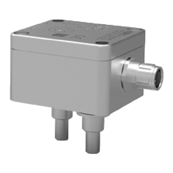
Getting started 3. Getting started 3.1. Unpacking Verify that you have received the following items: When you ordered ECO: • User’s manual • Conformation declaration (EU) • • T100 Control drawing for hazardous areas (ECO-Ex) 3.2. Ordering Elements 3.2.1. ECO Fig. -
Page 8: Installation
Installation 4. Installation 4.1. Mechanical Installation Depending on the version of the tap, the installation is performed differently. NOTE: Too much force will damage the sensor tip! 4.1.1. Plug tap Place Position the ECO so that the tapped holes in the sensor and the insertion tips match. Screw the ECO onto the sensor hand-tight using the hexagon socket screws (width across flats 3 mm) already inserted in the housing. -
Page 9: Ex Installation
Installation 4.3. Ex Installation The ECO ... -Ex are only intrinsically safe if they are operated via isolating amplifiers or supply isolators. The technical specifications in the document "T100 Control drawing for hazardous areas" must be observedT100 must be observed For mechanical installation, follow the installation instructions in chapter 4.1. -
Page 10: Operation
Operation 5. Operation 5.1. Normal Operation If the ECO is ordered together with a mechanical sensor, the ECO is already set to this and no further settings are required for operation. 5.1.1. Pin assignment and operating values of the output stages Version: ECO_M_ENG_220303_E002... -
Page 11: Possible Output Configurations
Operation 5.2. Possible output configurations ECO offers a variety of possible output configurations, which are defined as follows. A distinction is only made on the basis of the hardware configurations. 5.2.1. Digital configurations We refer to the frequency/pulse and NAMUR configurations as digital configurations. With dual-channel versions (ECO X2), you have the option of outputting the measured sensor signals directly, scaled (up to approx. -
Page 12: Analog Configurations
Operation 5.2.2. Analog configurations In addition to the frequency/pulse information, analog configurations offer the option of outputting a further analog output variable. The flow rate or the medium temperature is available as the reference variable for this analog information. The analog outputs also have the option of signaling an error. 5.2.2.1. -
Page 13: Fig 4: 0-20 Ma Analog Output And Npn Output With Scaled Frequency
Operation 5.2.2.2. 0-20 mA Active + Frequency/Pulse (PP, NPN, PNP) – ECO XX-FV-XX-X This configuration offers an active current loop in addition to the frequency/pulse functionality. Fig 4: 0-20 mA analog output and NPN output with scaled frequency 5.2.2.3. 0-10V Active + Frequency/Pulse (PP, NPN, PNP) – ECO XX-FW-XX-X Here, in addition to the frequency/pulse functionality, an active voltage output (0-10 V) is available. -
Page 14: Parameterization
Service and Maintenance 5.3. Parameterization A communication interface is implemented in the ECO, which uses a digital output for data transmission. Customer-specific parameterization can be carried out at the factory according to customer specifications. NOTE: During parameterization the outputs cannot be used, the ECO is supplied via the communication adapter. 5.3.1. -
Page 15: Service
For the addresses see the last page of this document. 7. Important Informationen 7.1. Warranty For warranty refer to the general terms and conditions of KEM Küppers Elektromechanik GmbH, which can be found on the corresponding website (www.kem-kueppers.com). Version: ECO_M_ENG_220303_E002... -
Page 16: Technical Data
Power Supply 12 ... 28 VDC, regulated Current Consumption < 25 mA Frequency Range 1 ... 5000 Hz; suitable for all KEM volumetric counters Output Stages Push-Pull active, PNP, NPN NAMUR 4-20 mA passive + Freq/Puls (NPN) 0- 20 mA active + Freq/Puls (PP, NPN, PNP) - Page 17 Important Informationen Operating values of the output stages Version: ECO_M_ENG_220303_E002...
-
Page 18: Dimensional Drawings
Important Informationen 7.3. Dimensional Drawings Fig 2: Dimensional Drawings ECO Version: ECO_M_ENG_220303_E002... -
Page 19: Weee Und Rohs
Important Informationen 7.4. WEEE und RoHS The unit described herein is not subject to the WEEE directive and the corresponding national laws. At the end of life forward the unit to a specialized recycling company and do not dispose it off as domestic waste. The unit described herein fully complies with the RoHS directive. - Page 20 Deutschland Deutschland T. +49 8131 59391-100 T. +49 9941 9423-37 F. +49 8131 92604 F. +49 9941 9423-24 sales@kem-kueppers.com service@kem-kueppers.com Weitere Distributoren & Partner finden sie unter: www.kem-kueppers.com Original KEM Dokument: ECO_M_ENG_220303_E002 Copyright KEM, Änderungen und Irrtümer vorbehalten Version: ECO_M_ENG_220303_E002...
Need help?
Do you have a question about the ECO Series and is the answer not in the manual?
Questions and answers