Sign In
Upload
Download
Table of Contents
Contents
Add to my manuals
Delete from my manuals
Share
URL of this page:
HTML Link:
Bookmark this page
Add
Manual will be automatically added to "My Manuals"
Print this page
×
Bookmark added
×
Added to my manuals
Manuals
Brands
Raymarine Manuals
Radar
R20XX
Operation manual
Raymarine R20XX Operation Manual
Raster scan radar
Hide thumbs
1
2
3
4
5
6
7
8
9
10
11
12
13
14
15
16
17
18
19
20
21
22
23
24
25
26
27
28
29
30
31
32
33
34
35
36
37
38
39
40
41
42
43
44
45
46
47
48
49
50
51
52
53
54
55
56
57
58
59
60
61
62
63
64
65
66
67
68
69
70
71
72
73
74
75
76
77
78
79
80
81
82
83
84
85
86
87
88
89
90
91
92
93
94
95
96
97
98
99
100
101
102
103
104
105
106
107
108
109
110
111
112
113
114
115
116
117
118
119
120
121
122
123
124
125
126
127
128
129
130
131
132
133
134
135
136
137
138
139
140
141
142
143
144
145
146
147
148
149
150
151
152
153
154
155
156
157
158
159
160
161
162
163
164
165
166
167
168
169
170
171
172
173
174
175
176
177
178
179
180
181
182
183
184
185
186
187
188
189
190
191
192
193
194
195
196
197
198
199
200
201
202
203
204
205
206
207
208
209
210
211
212
213
214
215
216
217
218
219
220
221
222
223
224
225
226
227
228
229
230
231
232
233
234
235
236
237
238
239
240
241
242
243
244
245
246
247
248
249
250
Table Of Contents
251
page
of
251
Go
/
251
Contents
Table of Contents
Troubleshooting
Bookmarks
Table of Contents
Warning
High Voltage
Antenna
Electromagnetic Energy
Table of Contents
Radar Glossary of Terms
Introduction
General
Equipment Features
Display Unit
Radome Antenna Unit Main Features
Open Array Antenna Unit Main Features
Specifications
Installation
Unpacking and Inspection
Equipment Supplied
Optional Accessories
Planning the Installation
Standard Spare Parts Kit
General System Diagram
Mounting the Display Unit
Typical Mounting Methids
Display Mounting Dimensions
Console Mounting Instructions
Console Mounting the Display
Radome Antenna Mounting
Outline Drawing of Radome Antenna Unit
Scanner Unit Weight
Universal Mast Mount
Typical Installation for Sailboat Shooting In-Line Connection
Connecting Procedure for Radome Antenna Unit
Wiring Diagram
J101 Connector Kit
Radar Interconnection Diagram
Assembling the Open Array Antenna
Assembly Procedure
The Completely Assembled Scanner Unit
Mounting the Open Array Antenna Unit
Typical Mounting Location
Setting the Radiation Plane
Base Mounting Dimensions
Ideal Radiation Plane
Outline Drawing
Cabling the Antenna Pedestal Unit
Antenna Pedestal Unit Cable Connection Procedure
Electrical Connections
DC Power Connection
Power Cable Size Versus Length
External System Interface
Display Rear Chassis
Connection with External Navaids
Installing the XX Heading Sensor
Minimum Mounting Distances
Interconnection
XX Heading Sensor Interconnection
INI-100 Wiring
Seatalk Interface
Seatalk Cable Options
Raychart Interface
Radar/Raychart Interconnection
Fishfinder Interface
External Video Output
Cable Connections for Master/Remote Monitor Operation
Dual Display Connections
Cable Connections for Selectable Master Operation
Interconnections, Dual Station Junction Box
Schematic Diagram, Dual Station Junction Box
Bonding
Continuous Metallic Deck or Bulkhead Procedure
Non-Metallic Decks and Bulkheads Bonding Procedure
Operation
Radar Map
Map Orientation
Effect of Ship's Movement
Navigational Echoes
Sea Return
Storm and Rain Squall Returns
Blind Sectors or Shadow Effect
Side Lobes
Radar Interference
False Echoes
Determining Radar Line of Sight Range
Radar Line of Sight Range Nomograph
Radar Controls
Marpa Readouts
Starting Operation
Initial Display Setup
Turn on Procedure
Shut down Procedure
Control Locations
Front Panel Operation
The Trackpad
Range Keys
Relation of Range, Rings and Pulse Length
VRM Key
EBL Key
Cursor Key
Off Center Key
Zoom Key
Enter Key
Tune Control
Auto Tune Mode
Rain Clutter Control
Sea Clutter Control
Gain Control
Menu Key
Radar Menu Layouts
Main Menu
Function Menu
Position
Waypoint
Route
Ir
Expansion
Timed-TX
Tune
Wakes
Radar Setup Menu
Range
Bearing
ALM Level
TX Pulse
Initial Setting Menu
Keyboard Dimmer
Display Brilliance
Language
Making a 360 Guard Zone
Setting a Sector Zone
Setting an Alarm Zone in Memory
3.5.16 RR/SHM Key
Heading Mode Key
North-Up Mode
Course-Up Mode
Heading/Reset Key
Window Key
Man Overboard Key
X-Mit/Off and ST-BY/OFF Keys
Using External Devices
External Navigator
Heading Sensor
Seatalk
Using Raychart
Marpa Operation
Glossary
True Vector
Relative
Starting Marpa
Marpa Definitions
Acquisition of Targets
Cancelling the Target
Marpa Readout Panel
Marpa Default Settings
Meaning of Symbols
Marpa Alarms
Dangerous Target Alarm
Lost Alarm
Technical Description
Radome Antenna Unit
Radome
Radiator Pattern
Functional Block Diagram of Radome Antenna Unit
Radiator Rotating Mechanism
Motor-Encoder
Bearing Reset Switch
Radiator
Bearing Reset Circuit
Transmitter Unit
Range, Pulse Length, and PRF Relationships
Receiver Unit
Receiver PCB
IF Amplifier Circuit
Video Detector Circuit
Time Table of the Transmitter
Receiver Unit Block Diagram
Video Output Circuit
Tuning Indication Circuit
Gain STC Circuit
Main Bang Suppressoin Circuit
Display Unit Functional Circuit Diagram
Simplified Block Diagram
Main Control PCB
Video Input Circuitry
A/D Converter
Buffer Memory
Video Memory
Control Pcbs
Graphic Control Memory
Video Output
Display Monitor
Optional Inputs
Power Supply
Marpa Pcb
Marpa Logic
Maintenance
Preventive Maintenance
High Voltage Arc Prevention
Inspection
Cleaning
Lubrication
Connector Maintenance
Radome Lubrication
Gasket Maintenance
Gasket Locations
Pedestal Motor Brush Replacement
Lubrication Location in Pedestal
Antenna Pedestal Brush Locations
Memory Battery Replacement
CRT Surface Cleaning
Fuse
Fuses Used
Recommended Test Equipment
Operation Checkout
Operation Checklist
Post Installation Setup Adjustments
Troubleshooting Guide
Master Reset
Alignments and Service
Antenna Pedestal Receiver Alignments
Receiver Gain Adjustment
Receiver Component Locations
Receiver STC Adjustment
STC Curve
Receiver Main Bang Suppression Adjustment
Tune Indicator Adjustment
Factory Adjustments
Display Alignments
Display AVR Voltage Adjustment
High Voltage Warning
Display Power Supply Test Points and Adjustment Locations
Contrast Adjustment
Focus Adjustment
Horizontal Hold Adjustment
Horizontal Size/Vertical Size Adjustment
Comparator Adjustment
Relative Bearing Adjustment
Display Timing Adjustment
Tune Preset Adjustment
STC Preset Adjustment
NM Alignment
Buzzer Volume Adjustment
Interlace Adjustment
Fishfinder Window Video Adjustment
Fault Finding Procedures
Typical Voltages
Radome Radar
Open Array Radar
Scanner Unit
Magnetic Sensor Compensation
XX Heading Sensor Compensation Adjustment
Compensation Procedure
INI-100 Compensation Adjustment
Parts List and Drawings
Generation Breakdown
Internal Connection Diagram, Radome Scanner Unit
Assembly Drawing
Parts Location List
Replaceable Parts List
Schematic Diagram, Terminal PCB
Component Location Drawing
Advertisement
Quick Links
1
Display Unit
2
Installation
Download this manual
Distributed by
Any reference to Raytheon or
RTN in this manual should be
interpreted as Raymarine.
The names Raytheon and RTN
are owned by the
Raytheon Company.
Table of
Contents
Previous
Page
Next
Page
1
2
3
4
5
Advertisement
Table of Contents
Related Manuals for Raymarine R20XX
Radar Raymarine R20 Operation Manual
Raster scan radar (250 pages)
Radar Raymarine Raytheon R20X Instruction Manual
Raster scan radar systems (97 pages)
Radar Raymarine hsb2 PLUS Quick Reference Card
Color lcd radar displays (2 pages)
Radar Raymarine R11XX Operation Manual
Raster scan radar (158 pages)
Radar Raymarine Raytheon Pathfinder Series Quick Start Manual
(9 pages)
Radar Raymarine Quantum 2 Installation Instructions Manual
Doppler radar scanner with raynet and wi–fi connections. supplied with a 10 m power cable. (100 pages)
Radar Raymarine SL72 Owner's Handbook Manual
Pathfinder radar and radar/chartplotter (243 pages)
Radar Raymarine SL70RC PLUS Series User Manual
Radar/chartplotter display (243 pages)
Radar Raymarine Quantum Radome Installation Instructions Manual
Chirp radar (54 pages)
Summary of Contents for Raymarine R20XX
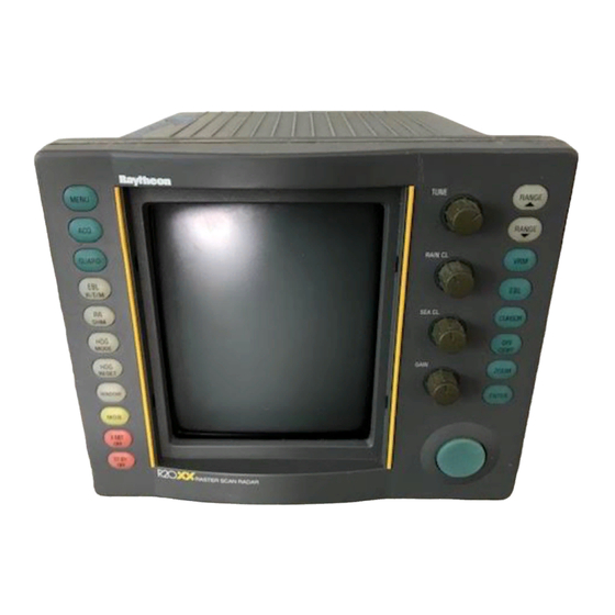
Page 1
Distributed by Any reference to Raytheon or RTN in this manual should be interpreted as Raymarine. The names Raytheon and RTN are owned by the Raytheon Company.
This manual is also suitable for:
R21xx
Table of Contents
Print
Rename the bookmark
Delete bookmark?
Delete from my manuals?
Login
Sign In
OR
Sign in with Facebook
Sign in with Google
Upload manual
Upload from disk
Upload from URL