Table of Contents
Advertisement
Quick Links
IP AI Cameras and Accessories
IP-FFC-AI-01(8027)
IP-DFC-AI-XX-XX(XXX)(8029, 8088, 8089)
MDR-HWU-01(7417)
Installation and Operation Guide
Please refer to
www.brigade-electronics.com
for the latest version of this manual
Brigade AI Cameras and Accessories (Various) Installation & Operation Guide V1.0 ENG
Advertisement
Table of Contents

Related Manuals for Brigade IP-DFC-AI Series


Summary of Contents for Brigade IP-DFC-AI Series
- Page 1 IP AI Cameras and Accessories IP-FFC-AI-01(8027) IP-DFC-AI-XX-XX(XXX)(8029, 8088, 8089) MDR-HWU-01(7417) Installation and Operation Guide Please refer to www.brigade-electronics.com for the latest version of this manual Brigade AI Cameras and Accessories (Various) Installation & Operation Guide V1.0 ENG...
-
Page 2: Table Of Contents
Table of Contents Introduction to IP AI Cameras and Accessories IP-FFC-AI-01 - Forward Facing Camera Product Appearance Product Features 2.2.1 Basic Features 2.2.2 AI Features Kit Content Optional Accessories Connection Diagram Installation 2.6.1 Product Hardware 2.6.2 Installation and Set Up IP-DFC-AI-XX-XX(XXX) –... -
Page 3: Introduction To Ip Ai Cameras And Accessories
MDR 600 Series Installation & Operational Guide. It is imperative that Brigade IP AI cameras are fitted and commissioned by competent and trained technicians. The installers are responsible for the correct setup of the overall system and must adhere to relevant regulations and legislation. -
Page 4: Product Features
This alert is currently disabled by default as it has not been fully tested to Brigade’s standards. It is recommended not to enable this function until a communication is made by Brigade to confirm it is having been released for use. -
Page 5: Kit Content
Kit Content Camera Link Card Cleaning wipes Cable Grub IP-FFC-AI-01-C IP-FFC-AI-01-QR Link Card Cleaning Pad IP-FFC-AI-01-GRUB Note: the cable grub only used in bottom cable exit Optional Accessories 3M Pad Cable Grub IP-FFC-AI-01-3M-PAD IP-FFC-AI-01-GRUB Note: the cable grub only used in bottom cable exit. Connection Diagram IP AI Camera Generic Figure 5... -
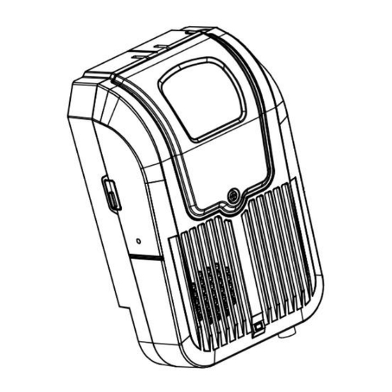
Page 6: Installation
The MDR is the host in the system which supplies power and processes the AI data transmitted from the IP AI cameras. Since IP-FFC-AI-01 equipped with Brigade’s standard 6-pin connector, it can connect directly to the IP camera connections on the MDR-644 or 641. -
Page 7: Ip-Dfc-Ai-Xx-Xx(Xxx) - Driver Facing Cameras
To adjust the camera lens angle, please use the M2.5 Philips screwdriver to loosen the cover screw and take off the upper cover to reveal the inside of the housing. Use the Philips screwdriver again to loosen the locking screw. The lens angle can be adjusted to fit windshields with rakes between 20°... -
Page 8: Ip-Dfc-Ai-Ws-01 - Ip Ai Camera Driver Facing Windscreen Mount
IP-DFC-AI-WS-01 – IP AI Camera Driver Facing Windscreen Mount 3.1.1 Figure 11: DFC camera with Windscreen Mounting bracket IP-DFC-AI-DB-01 – IP AI Camera Driver Facing Dashboard Mount 3.1.2 Figure 12: DFC camera with Dashboard mounting bracket IP-DFC -AI-AP-01 – IP AI Camera Driver Facing A-Pillar Mount 3.1.3 Figure 13: DFC camera with A-Pillar Mounting bracket Product Features... - Page 9 The audible mp3 voice alerts can be heard when the Driver facing camera connects to a recorder with speaker be it the built-in speaker of the AI Connected Dashcam or from a monitor connected to the MDR. The pictures below show when the relevant alerts are triggered; the video playback is obtained from the algorithm play mode in the Brigade Video Telematics Platform.
-
Page 10: Compatibility
The trigger conditions (which include speed, duration (time) and effective time) are configurable. However, the default settings recommended by Brigade are already pre-set and are based on comprehensive testing. Installer/Fleet manager can change the trigger conditions to suit the needs of the fleet or industry if needed. -
Page 11: Kit Content
Kit Content 3.4.1 IP AI Camera Driver Facing Windscreen Mount (IP-DFC-AI-WS-01) IP AI camera Driver Facing Hex key and Link Card Windscreen Mount Alcohol wipe IP-DFC-AI-01 IP-DFC-AI-01-C and DFC-BRKT-WS-01-FIX QR LINK CARD DFC-BRKT-WS-01 3.4.2 IP AI Camera Driver Facing Dashboard Mount (IP-DFC-AI-DB-01) IP AI Camera Driver Facing Hex key and Link Card... -
Page 12: Optional Accessories And Spares
Optional Accessories and Spares 3.5.1 Mounting Brackets 3.5.1.1 Windscreen Mounting Bracket Kit (including the 3M pad) Windscreen Mounting Bracket – Windscreen Mounting Bracket DFC-BRKT-WS-01 Fixing Kit DFC-BRKT-WS-01-FIX 3.5.1.2 Dashboard Mounting Bracket Kit Dashboard Mounting Bracket Dashboard Mounting Bracket – Fixing Kit DFC-BRKT-DB-01 DFC-BRKT-DB-01-FIX 3.5.1.3... -
Page 13: Fitting Brackets To The Driver Facing Camera
Fitting Brackets to the Driver Facing Camera 3.6.1 Windscreen Mounting Bracket The following are needed for the assembly: Driver facing camera (see section 3.4.1 for details) Windscreen Mounting bracket bits (see section 3.4.1 for details) Windscreen Mounting bracket fixing kit (see section 3.4.1 for details) 2.0mm hex key (red hex key depicted below) Phillips PH1 or PZ1 Screwdriver (depicted below) Figure 20 Tools need to fit Windscreen Mounting Bracket to DFC camera that are not kit content... - Page 14 Figure 24: Items required to connect the camera to the ball joint Figure 25: Assembled camera to ball joint Step 3: Place the ball joint (with camera attached) inside the cup of the bracket base and secure with clamping piece. Figure 26: Connection to the larger piece with flat base of the mounting bracket Figure 27: Fitting the second piece of the mounting bracket to cover the ball joint Step 4: Secure the clamping bracket in place using the 4x M 2.5 x 7mm hex screws.
- Page 15 Figure 28: kit for fixing the bracket pieces to the ball joint. Step 5: Fit the 3x 2.5mm silver grub screws, as shown in Figure 28, to temporarily secure the camera position for installation. Figure 29: Fixing the orientation of the camera with the silver grub screws. To disassemble the components please follow the instructions above in the reverse order.
-
Page 16: Dashboard Mounting Bracket
3.6.2 Dashboard Mounting Bracket The items that are needed for this are: Driver facing camera (see section 3.4.2 for details) Dashboard Mounting bracket bits (see section 3.4.2 for details) Dashboard Mounting bracket fixing kit (see section 3.4.2 for details) 3.0mm hex key (a silver-coloured hex key comes with the bracket fixing kit, however a red 3.0mm hex key depicted below will be used for illustration of the assembly instructions) The steps for fitting the dashboard mounting bracket to the driver facing camera are as below: Step 1: Check that all part listed are present and recommended tools are available. -
Page 17: A-Pillar Mounting Bracket
Figure 33: Fitting the camera to the mounting bracket To disassemble the components please follow the instructions above in the reverse order. 3.6.3 A-Pillar Mounting Bracket The items that are needed for this are: Driver facing camera (see section 3.4.3 for details) A-Pillar Mounting bracket bits (see section 3.4.3 for details) A-Pillar Mounting bracket fixing kit (see section 3.4.3 for details) 3.0mm hex key (a silver-coloured hex key comes with the bracket fixing kit, however a red 3.0mm hex key... - Page 18 Figure 36: A-Pillar mounting bracket using the hex head screw and hex key to fix the two pieces together. Step 4: Connect piece number 1 to the number 2 piece ensuring that the grooves on the pieces align. Figure 37: A-Pillar mounting bracket connecting the top to the middle piece of the bracket Step 5: Fix the top piece to the middle piece using the second M4 x 11mm hex screw and the 3.0mm hex key provided.
-
Page 19: Installation
Step 7: Fit the camera to the bracket, ensuring that the marking on the plastic disc and the top piece of the bracket align. Figure 40: Fitting the camera to the mounting bracket Step 8: Use the third hex M4 x 11mm head screw to fix the bracket assembly to the camera Figure 41: fixing the camera to the mounting bracket with the third hex head screw Installation During vehicle installation it is recommended that the driver facing camera be installed on the driver side of the vehicle between 50cm to... - Page 20 Step 1: Power the device. Ensure that the device is powered on and connected to the SmartController app. Go to the preview section to view the real time footage of the powered camera. Step 2: Determine the camera installation position whilst reviewing the real time image to ensure a fairly accurate position. Ensure that the camera is as close to the A-pillar as possible to reduce the obstruction to the driver’s view.
-
Page 21: Dashboard Mounted Driver Facing Camera
degrees, the middle grub screw will get lost in the hole at the base of the ball for connecting the bracket to the camera. Figure 45: Pictures showing base of the ball joint at 90-degree angle, the hole at the base of the ball is about 16mm deep while the middle grub screw is only 5mm long. - Page 22 It is also recommended that the camera is installed such that the driver’s face is in the centre of the image and that the distance between the line of sight of driver and the camera is between 50cm to 100cm. Figure 47:Depicting the positioning of the driver during and after the camera is installed.
-
Page 23: A-Pillar Mounted Driver Facing Camera
3.7.3 A-Pillar Mounted Driver Facing Camera This is the most versatile and preferred mounting option if using self-tapping screws is acceptable. It allows the camera to be mounted away from the windshield and the dashboard reduces the impact of the driver facing camera causing obstruction to the driver’s view by the virtue of its location. - Page 24 360° Figure 51: A-Pillar Driver facing camera showing the degree of movement of the camera head/top bracket piece joint when it hex head screw is loosened. 180° 360° Figure 52: A-Pillar Driver Facing camera showing the degree of movement of the top piece and middle piece joint (red) and the Middle piece/base piece joint (green) Note: The middle piece/Base joint rotation (green) should only be adjusted before installing the camera because the adjusting hex head screw is at the bottom of the base piece which will be difficult to access...
- Page 25 Figure 54: A-Pillar Driver facing camera showing self -tapping screw fixed on the lower section of the base of the bracket and the lens positioning hex head screws tightened. Peel off the protective plastic on the glass face of the camera to complete the installation.
-
Page 26: Calibration
1) Open SmartController App on mobile devices and connect to the MDR which takes AI cameras. For details on how to use the SmartController App, please refer to MDR SmartController (6628) - Installation Guide V1.0 ENG WEB in Brigade Product Support site. -
Page 27: Mdr-Hwu-01 - Hazard Warning Unit
MDR-HWU-01 – Hazard Warning Unit Hazard Warning Unit (HWU) is a display accessory which must be use with a host device, such as MDR 600 series and AI Dashcam series. HWU itself does not contain any AI process capabilities; it is controlled by the host. When host received AI alarms, it will pass information to the HWU which will correspondingly display the correct alert symbol or beep sound to notify the end user. - Page 28 Drive Fatigue Level 1 / Level 2 Continuous beeping Phone Call Level 1 / Level 2 Beep once Smoking Level 1 / Level 2 Beep once Driver Distraction Level 1 / Level 2 Beep once No Driver Level 1 / Level 2 Beep once After 2 seconds Seatbelt...
-
Page 29: Kit Content
5.2.2.2 Status Display Status Display System initialisation icon The system is initialising. System Activated Icon The system has been activated. System Offline Icon The system is in an inactive state, or in the process of being upgraded. Multi-information display TTI (time to impact), Pedestrian collision warning (upper centre), Driving behaviour detection Alarm (upper right corner). -
Page 30: Connection Diagram
Connection Diagram 5.5.1 MDR 641 Series Connection Diagram For connection to the MDR 641, adapter cable MDR-AC-HWU-01 which is 12-pin female connector 6-pin female mating face. MDR-AC-HWU-01 Figure 59 MDR-HWU-U connection diagram to MDR 641 with transfer cable 5.5.2 MDR 644 Series Connection Diagram For connection to the MDR 644, the HWU can be directly plugged into the MDR 644 without additional adaptors. -
Page 31: Installation
This information is addressed to the operator of the vehicle where a Brigade MDR 600 Series System is installed: 1) The Brigade MDR 600 Series is intended to be used as a mobile digital recorder. Drivers and operators should not interact with the MDR setup menu. -
Page 32: Maintenance And Testing
HDD recordings to start after a file-system check. 6) This test can only be performed when the MDR video output is displayed on a Brigade monitor. Ensure that both the SD card and HDD are recording. Recording is shown with an SD card symbol and HDD symbol. -
Page 33: Approvals
Approvals UNECE Regulation No. 10 Revision 6 (“E-marking”) EU Declaration of Conformity: The full text of the EU and UKCA declaration of conformity for each product are available at the following internet address: www.brigade- electronics.com... -
Page 34: Glossary
Glossary 3G – Third Generation ID – Identification 4G – Fourth Generation IO – Input/output AC – Adaptor Cable iOS – iPhone Operating System (Apple Inc.) ADPCM – Adaptive Differential Pulse-code Modulation IP – Internet Protocol G711U – Narrowband audio codec IR –... -
Page 35: 10 Disclaimer
Mobile digital recorder systems are an invaluable driver aid but do not exempt the driver from taking every normal precaution when conducting a manoeuvre. No liability arising out of the use or failure of the product can in any way be attached to Brigade or to the distributor. Dénégation Verwerping Les enregistreurs numériques portables sont une aide précieuse... - Page 36 18/11/2024 15:58:59 Brigade AI Cameras and Accessories Installation & Operation Guide - V1.0 ENG WEB...
Need help?
Do you have a question about the IP-DFC-AI Series and is the answer not in the manual?
Questions and answers
my connector is broken I need to know the connection of the connector i camera be 800c especially the colors white, blue, green and yellow from my camera... thank you very much in advance