Mackie PPM1012 - Powered Mixer Manual
- Owner's manual (36 pages) ,
- User manual (36 pages) ,
- Specification (7 pages)
Advertisement
Read This Information!
We realize that you must be really keen to try out your new powered mixer. Please read the safety instructions and this page, and the rest can wait until you're ready. But please read it — you'll be glad you did.
Setup
Make sure there is at least 6 inches of airspace behind the powered mixer for ventilation. There are two fans inside to cool the power amplifier section. Use the powered mixer in a nice clean environment, free from dryer lint and dust bunnies.
Zero the controls
- Fully turn down all the faders and controls, except for the channel EQ, graphic EQ faders, and pan controls, which should be centered.
- Make sure all buttons are in the out position.
Connections
- Make sure the AC power switch is off before making any connections.
- Push the linecord securely into the IEC connector on the rear panel, and plug it into a 3-prong AC outlet that is properly configured for the voltage of your powered mixer.
- Plug a balanced microphone into one of the mic XLR (3-pin) connectors. Or connect any linelevel signal (keyboard, or guitar preamp) to a line input jack using a TS or a TRS 1/4" plug.
- If your microphone requires phantom power, press in the 48V phantom power button.
- You can connect a guitar directly to line inputs 7 or 8 without need for a DI box. Press the hi-z switch on these channels if you do.
- The insert jacks can be used to connect an external effects or dynamics processor into the signal chain. See Connection Section for more details.
- Plug the speakers (4 ohms or greater) into the speaker output jacks on the rear panel. If you plug two speakers into a side, each speaker must be 8 ohms or greater to maintain a 4-ohm minimum load on the amplifier. Use at least 18 gauge speaker cable with 1/4" TS plugs. For now, set the power amp mode switch to stereo mains.
 Don't use guitar cords for speaker cables! They're not designed to handle speaker-level signals and could overheat.
Set the levels
It's not even necessary to hear what you're doing to set optimal levels. But if you'd like to: Plug headphones into the phones output jack, then turn up the phones knob just a little.
- Turn on the PPM1012 by pressing the top edge of the power switch.
- For one channel, press the solo switch in, and the rude solo light will turn on.
- Play something into that input at real-world levels.
- Adjust that channel's gain control until the left main meter stays around the 0 dB LED (marked "level set").
- Disengage the channel's solo switch.
- Repeat steps 2 to 5 for the remaining channels.
- In normal playing, the channel's OL LED should only light occasionally. If it stays on for a large portion of your performance, check that the gain control is set correctly.
- Turn up the channel faders to the "U" mark.
- Slowly turn up the main level fader until you hear the signals in your speakers.
- If needed, apply some EQ wisely.
- Adjust the channel faders to get the best mix. Keep the gain controls and faders fully down on unused channels.
Other Notes
- Only connect the powered mixer's speaker-level outputs to passive loudspeakers.
- For optimum sonic performance, the channel faders and main mix fader should be set near the U (unity gain) markings.
- When shutting down, turn off any external amplifiers first. When powering up, turn on any external amplifiers last. This will reduce the chance of turn-on or turn-off thumps in your speakers.
- Save the shipping box!
Introduction
This powerful mixer is designed to meet the needs of almost any small to medium-sized club/meeting room/sanctuary/outdoor gathering.
At Mackie, we know what it takes to be roadworthy. After all, our mixers have traveled all over the world under the worst of conditions and the best of conditions, and we've applied what we've learned to the mechanical design of our powered mixers.
Reliability is paramount to sound reinforcement. That's why our engineers have subjected our powered mixers to the most rigorous and fiendish tests imaginable to fine-tune the design and extend its limits beyond those of ordinary mixers or amplifiers.
Features
- Two internal power amplifiers, each rated at 800 watts peak into 4 ohms
- 3 selectable amplifier modes (stereo main, mono-main/monitor 1, mon1/mon2)
- 12 channels (8 mono, 2 stereo)
- Mic inputs on 8 channels
- Line-level inputs (8 mono, 2 stereo)
- Tape out for recording the main mix
- Tape in for playing intermission music
- Break switch mutes all channels except tape in
- Insert jacks on mono channels
- Low cut switch on mono channels
- Instrument switches on channels 7 and 8 allow direct connection of guitars without a DI box
- 3-band EQ with sweepable mid-range frequency on mono channels
- 4-band EQ on stereo channels
- Monitor 1 and Monitor 2 send
- FX 1 and FX 2 send
- Main mix stereo line-level outputs
- Main mix mono line-level output with level control, and switchable low-pass filter with variable frequency for subwoofer work
- Stereo main insert allows the connection of inline devices in the main mix
- +48v Phantom power can be applied to all mics
- Built-in compressors on the first 6 mono inputs (dedicated in-line compression)
- Two independent internal FX processors, each with 24 Running Man 32-bit effects with input gain, tap delay, and mute/unmute
- Footswitch connection for FX mute/unmute
- 9-band, constant-Q, graphic EQ on main mix, assignable to monitor 2
- 9-band, constant-Q, graphic EQ on monitor 1
- 12-segment stereo output meters on main mix
- LED meter on each channel
- Solo switch on each channel, FX 1 and FX 2 return, mon 1 and mon 2
- Mute switch on each channel and FX 1 and FX 2 return
- Speakon and 1/4" power amp outputs
- Precision passive switch for enhanced clarity and low-frequency response with Mackie passive speakers
- Headphones play main mix, or soloed channels
How To Use This Manual
The first pages after the table of contents are the hookup diagrams. These show typical setups for fun times with your powered mixer.
Next is a detailed tour of the entire mixer. The descriptions are divided into sections, just as your mixer is organized into distinct zones:
- Rear Panel
- Connection Section
- Channel Controls
- Master Controls
- Stereo Effects Processors
Throughout these sections you'll find illustrations with each feature numbered and described in nearby paragraphs.
This icon marks information that is critically important or unique to the mixer. For your own good, read them and remember them.
 This icon will lead you to some explanations of features and practical tips. Go ahead and skip these if you need to leave the room in a hurry.
- Service information.
- Connectors.
- Technical information.
- Table of Presets
The thickness of the manual makes it ideal for covering your head, especially when a 15-mile wide meteorite bursts through the earth's atmosphere, heading straight for your camp site at Lucky-Duck Lake, WA.
Hookup Diagrams
Club System

This diagram shows microphones attached to channels 1 and 2, electric guitars connected directly to channels 7 and 8 (with hi-z switch pressed in), and a keyboard attached to channels 9/10. A portable recorder is attached to the stereo tape outputs to record the performance.
Mackie SRM450v2 powered monitors are connected to the monitor 1 send, and play as stage monitors. The mon 1 knobs of each channel allow you to set up a stage monitor mix that is independent of the main mix.
Passive speakers are connected to the speaker-level power output of the powered mixer, and they play the main stereo mix to your audience. SWA1801z powered subwoofers are connected to the main mix mono out, to reinforce the low end in your system. For powered subwoofers like these with their own internal crossover, leave the mixer's LPF (low-pass-filter) switch out.
House of Worship

This diagram shows microphones attached to the mic inputs of channels 1 to 4, an electric guitar connected directly to channel 7 (with hi-z switch pressed in), an acoustic guitar microphone connected to channel 8 mic in, a keyboard attached to channels 9/10, and a drum machine to channels 11/12.
A Mackie SRM150 powered monitor is connected to the monitor 2 send, and acts as a personal stage monitor to your talented, yet still surprisingly-humble keyboard player. The mon 2 knobs of each channel allow you to set up a monitor mix that is independent of the main mix.
The power amp mode switch is set to play the mono main mix on ch. A, and monitor 1 mix on ch. B.
Passive speakers are connected to channel A speaker-level power output, and they play the main mono mix to your audience. C300z passive stage monitors are connected to channel B speaker-level power output, and they play the stage monitor mix 1 to your performers.
Passive subwoofers are powered by an amplifier connected to the main mix mono out, to reinforce the low end in your main mix. Press the LPF (low-pass-filter) switch in, and adjust the LPF frequency control to suit your subwoofers. The external amplifier will then only receive the low frequency range.
DJ System

This diagram shows microphones connected to the mic inputs of channels 1 and 2, a wireless microphone receiver connected to the mic input of channel 4, and a graphic EQ connected to channel 4's insert jack (to help control any feedback in the wireless mic). An iPod docking station is attached to channels 11/12, using RCA to 1/4" TS adaptors.
Two turntables are connected to a Mackie d.2 Pro DJ mixer, and its output connect to channel 9/10 stereo line inputs. Use the d.2 Pro's advanced DJ controls to get the best performance from your records. Use the powered mixer to play the d.2 Pro output, and control the mics and iPod.
The power amp mode switch is set to play the stereo main mix in the passive speakers, connected to the speaker-level power outputs.
Mackie HD1521 powered speakers and powered subwoofers are connected to the line-level main mix outputs, and also play the stereo main mix to your audience.
Band System

This diagram shows microphones attached to the mic inputs of channels 1 to 4, electric guitars connected directly to ch. 7 and 8 (with hi-z switch pressed in), a line-level effect connected to ch.7 insert, a keyboard attached to channels 9/10, and an electronic drum kit attached to channels 11/12. Add vocal compression as required, by tweaking the compression knobs on channels 1 to 4.
The rear-panel power amp mode switch is set to play the monitor 1 mix on channel A, and monitor 2 mix on channel B.
Mackie HD1531 powered speakers and powered subwoofers are connected to the line-level main mix outputs, and play the stereo main mix to your audience. The subs play the low frequencies, and the HD1531s play the mid and top range.
C200 passive stage monitors are connected to the channel B speaker-level power output of the powered mixer. These play the stage monitor 2 mix to your performers. C300z passive stage monitors are connected to the channel A speaker-level power output, and play the stage monitor 1 mix.
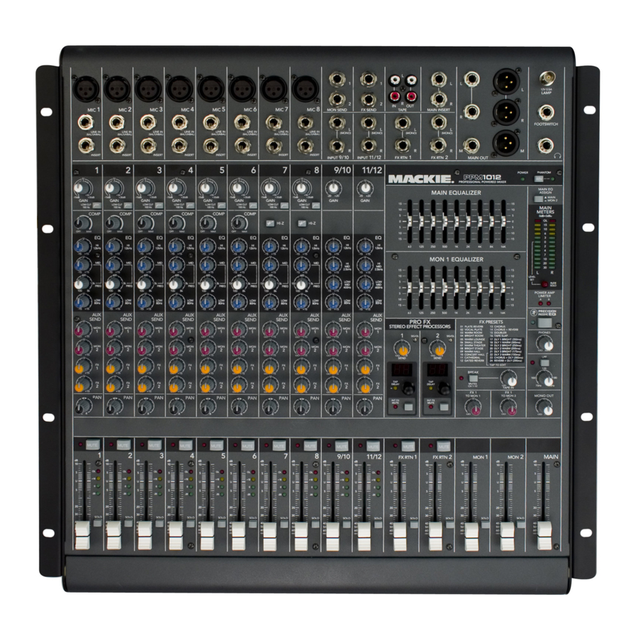
PPM1012 Features
Rear Panel

 POWER CONNECTION
This jack accepts the supplied 3-prong IEC AC power cord.
Before you plug the AC power cord into the powered mixer, make sure that the voltage of your unit is the same voltage as your local AC mains supply. Use only the power cord supplied. Also, disconnecting the plug's ground pin is dangerous. Please don't do it. And no running with scissors either. Let's be safe out there!
 POWER SWITCH
Press the top of this rocker switch inwards to turn on the mixer. The front panel power LED [42] will glow with happiness, or at least it will if you have the mixer plugged into a suitable live AC mains supply.
Press the bottom of this switch to turn off the mixer, whenever you feel that this would be a safe thing to do. Half-way through a heavy metal guitar solo might not be such a good time.
As a general guide, you should turn on your powered mixer first, before any external power amplifiers or powered speakers, and turn it off last. This will reduce the possibilities of any turn-on, or turn-off thumps in your speakers.
 SPEAKER-LEVEL OUTPUTS
These output connections provide speaker-level output power from the internal power amplifiers to your passive speakers. The outputs can be selected with the amp mode switch [53] to be either the stereo main mix, mono main mix/monitor 1, or monitor 1/monitor 2.
The power output of the PPM1012 is 500 watts rms per channel into 4 ohms, and 800 watts peak.
Two common types of connector are provided for your convenience: Speakons and 1/4" TS.

- Speakon outputs are wired Pin 1+ positive (hot) and Pin 1– negative (cold).
Mono Speakon Connection

- 1/4" TS outputs are wired Tip positive, and Sleeve negative.
1/4" TS Connection
These two types of outputs are wired in parallel, and it is possible to use both types at once.
The minimum impedance that the powered mixer can handle is 4 ohms per channel, and we recommend that you do not go below this.
If you are using both outputs per channel, make sure each loudspeaker is 8 ohms impedance or greater.
 VENTILATION
These holes in the rear panel allow the internal fans to flow breezy and minty-fresh cooling air over the internal power amplifiers. Do not obstruct these holes, or the amplifiers may overheat and shut down. Do not remove the feet, as these help keep the powered mixer off the ground for ventilation.
Connection Section

This is where you plug in things such as: microphones, line-level instruments, guitars, and effects, a recorder, PA system, powered monitors, powered subwoofer etc. (The speaker-level outputs from the internal power amplifiers are on the rear panel.) Check out the hookup diagrams for some connection ideas. See "Connections" for further details and some rather lovely drawings of the connectors you can use with your mixer.
 MIC INPUTS
We use phantom-powered, balanced microphone inputs just like the big studio mega-consoles, for exactly the same reason: This kind of circuit is excellent at rejecting hum and noise. You can plug in almost any kind of mic that has a standard XLR-type male mic connector.
Professional ribbon, dynamic, and condenser mics all sound excellent through these inputs. The mic inputs will handle any kind of mic level you can toss at them, without overloading.
Microphone-level signals are passed through the mixer's splendid microphone preamplifiers to become line-level signals.
Channels 1 to 6 have the extra benefit of dedicated in-line compressors [25]. These can be adjusted to add just the right amount of compression to your vocals and help prevent distortion and overloading.
PHANTOM POWER
Most modern professional condenser mics require 48V phantom power, which lets the mixer send low-current DC voltage to the mic's electronics through the same wires that carry audio. (Semi-pro condenser mics often have batteries to accomplish the same thing.) "Phantom" owes its name to an ability to be "unseen" by dynamic mics (Shure SM57/SM58, for instance), which don't need external power and aren't affected by it anyway.
The mixer's phantom power is globally controlled by the phantom [43] switch. (The phantom power for all channels is turned on and off together.)
Never plug single-ended (unbalanced) microphones, or ribbon mics into the mic input jacks if phantom power is on. Do not plug instrument outputs into the mic XLR input jacks with phantom power on, unless you know for certain it is safe to do so.
 MONO LINE INPUTS (Ch. 1 to 6)
These 1/4" jacks share circuitry (but not phantom power) with the mic preamps, and can be driven by balanced or unbalanced sources.
To connect balanced lines to these inputs, use a 1⁄4" Tip-Ring-Sleeve (TRS) plug.
To connect unbalanced lines to these inputs, use a 1⁄4" mono (TS) phone plug or instrument cable.
 LINE/INSTRUMENT INPUTS (Ch. 7 and 8)
The line-level inputs for channels 7 and 8 can also accept instrument-level signals if the hi-z switches [26] are pressed in. This allows you to connect guitars directly to channels 7 and 8, without the need for a DI box. The input impedance is optimized for direct connection, and high-frequency fidelity is assured.
 STEREO LINE INPUTS (Ch. 9/10 and 11/12)
These channels have stereo line inputs. If you just have a mono source, plug it into the left input channel 9 or 11 (labeled left/mono), and the signal will appear (as if by magic) equally on the left and right of the main mix.

 INSERT (Ch. 1 to 8)
These unbalanced 1/4" jacks on channels 1 to 6, are for connecting serial effects processors such as compressors, equalizers, de-essers, or filters. The insert point is after the gain control [23] and compressor [25] circuits (on channels 1 – 6), but before the channel's EQ [27-32] and fader [40]. The channel signal can go out of the insert jack to an external device, be processed (or whatever) and come back in on the same insert jack. To do this requires a special insert cable that must be wired thusly:
")
Tip = send (output to effects device)
Ring = return (input from effects device)
Sleeve = common ground
Insert jacks can be used as channel direct outputs; post-gain, and pre-EQ. See the connector section (figure G) showing three ways to use insert cables.
 MON SEND 1 and MON SEND 2
These 1/4" TRS connectors allow you to send the monitor line-level output to stage monitors. These could either be passive stage monitors powered by an external amplifier, or powered stage monitors with their own amplifier built in.
Mon send 1 and mon send 2 are independent of each other, so you can set up two separate monitor mixes. If you only need to set up one monitor mix, use monitor 1, as it has its own graphic EQ [45].
The monitor 1 signal is the sum (mix) of all the channels whose mon 1 control [33] is set to more than minimum. The monitor 2 signal is the sum (mix) of all the channels whose mon 2 control [34] is set to more than minimum. The overall monitor 1 output level can be adjusted with the mon 1 master level fader [58] and its EQ tweaked with the monitor 1 graphic EQ [45].
The monitor outputs are not affected by the main fader [59], or the channel faders [40]. This allows you to set up the monitor mixes and levels just right, and not have them change every time a channel level or the main mix level is adjusted. This is the main aim of a monitor mix: independence from the main mix.
 FX SEND 1 and FX SEND 2
These 1/4" TRS connectors allow you to send the FX line-level outputs to external effects processors, while disconnecting the internal effects processors.
FX send 1 and FX send 2 are independent of each other, so you can set up two separate effects processors.
The FX 1 output signal is the mix of all the channels whose FX 1 control [35] is set to more than minimum. The FX 2 signal is the mix of all the channels whose FX 2 control [36] is set to more than minimum.
The FX outputs here do not include processed audio from the internal effects processors. When something is plugged into one of these outputs, the signals that normally feed the internal effects processor are disconnected, and come out of these outputs instead. This prevents you from doubling-up on effects.
Both FX outputs are affected by the channel level faders [40]. This allows you to set up the FX level just right, and have it follow any change made to the channel levels.
In normal use, the unprocessed (dry) mono FX sends would go to an external effects processor. The stereo processed (wet) output from the external effects processor would connect to the stereo FX returns [12]. The FX return faders [57] allow you to adjust how much of the wet signals appear in the main mix.
 . FX RTN 1 and FX RTN 2
These 1/4" TRS input connectors allow you to add the stereo processed output from external effects processors to the main mix. Adjustment of the incoming signals is made with the FX return faders [57]. The signals can also be muted and soloed (and so cued up in headphones) like any other input.
You can also use these inputs to add any stereo linelevel signals to your main mix, so it could be another source, not just an effects processor. The inputs are similar to the channel line-level inputs, only without the gain control, channel EQ or pan. A sample of the FX 1 return can be added to monitor 1 and 2 using the FX 1 to mon 1 [56] and FX 1 to mon 2 controls.
 TAPE INPUTS
These stereo unbalanced RCA inputs allow you to play a tape, CD or other line-level source whenever the band is taking a break. The input is only enabled when the break switch [51] is engaged, at which time, the main mix is bypassed, and only the tape input will play in the main loudspeakers.
 TAPE OUTPUTS
These stereo unbalanced RCA outputs allow you to record the main stereo mix onto a tape deck, hard disk recorder, automatic CD burner, or a computer, for example. This lets you make a recording for posterity/archive/legal purposes whenever the band gets back together again.
The tape output is the stereo main mix, but it is not affected by the main fader [59], or the main graphic EQ [44].
 MAIN INSERTS
These unbalanced 1/4" TRS jacks can be used for connecting serial effects processors such as compressors, equalizers, de-essers, or filters. The insert point is before the main mix master graphic EQ [44] and the main mix fader [59]. The main mix signals can go out of the insert jack to an external device, be processed (or whatever) and come back in on the same insert jack. To do this requires a special insert cable that must be wired thusly (just like a channel insert):

Tip = send (output to effects device)
Ring = return (input from effects device)
Sleeve = common ground
 MAIN OUTPUTS
These balanced 1/4" TRS and XLR outputs supply the stereo main mix at line-level. You can connect these outputs to the line-level inputs of external power amplifiers running passive loudspeakers, or to the inputs of powered loudspeakers. This is useful if you need more power, or if you already have this equipment. Then you can use the internal amplifiers to power other loudspeakers, such as passive monitors, after setting the amp mode switch [53] appropriately.
These line-level outputs play the same signal as the speaker-level outputs [3] (when set to stereo mains).
 MAIN MONO OUTPUT
These 1/4" TRS and XLR connectors supply a copy of the main mix summed together in glorious living mono. This is ideal for running a mono PA system, by connecting to the inputs of an external power amplifier running a passive loudspeaker, or directly to a powered loudspeaker. Whatever adjustments you make to the main mix, will affect this output. The output here can be adjusted with the mono out control [55], and turned up or down relative to the main left and right outputs.
When the low pass filter (LPF) switch [54] is engaged, the mono output passes only the frequency range below the frequency set by the low-pass control [54]. This allows you to use the mono output to run to the inputs of powered subwoofers, or to the inputs of amplifiers running passive subwoofers. (The main left and right outputs still play the full frequency range.) Tweaking the mono out control will allow you to balance the subwoofer output with the left and right mains.
 HEADPHONE OUTPUT
This 1/4" TRS connector supplies the output to your stereo headphones.
In normal operation, you will hear the main left and right mix, and the headphones volume level can be adjusted with the phones level control [19]. The main mix fader [59] will also affect the headphones level.
Whenever a solo switch [41] is engaged, you will only hear the soloed channel(s) in the headphones. This gives you the opportunity to audition the channels before they are added to the main mix. (Solo signals reaching the headphones are not affected by the channel faders or main fader, therefore turn down the phones level first, as soloed channels may be loud.)
The phones output follows standard conventions:
Tip = Left channel
Ring = Right channel
Sleeve = Common ground

The headphone amp is loud, and can cause permanent ear damage. Even intermediate levels may be painfully loud with some earphones. BE CAREFUL! Always turn the phones level control [19] all the way down before connecting headphones or pressing a solo switch, or doing anything new that may affect the headphone volume. Then turn it up slowly as you listen carefully.

 LEVEL
LEVEL
This knob controls the level of the signal going to your stereo headphones.
Make sure this is fully down whenever you are making connections in your system, or putting on the headphones, or before you press any solo switch [41]. Bring up the level slowly and carefully to protect your hearing.
 FX FOOTSWITCH CONNECTOR
This is where you connect a footswitch. (Any two-button on/off footswitch will do). This allows you to easily mute or un-mute the two internal effect processors independently, while stamping your foot and looking like you were mad about something.
The output is wired so the tip affects FX1, and the ring affects FX2.
If the internal effects have already been muted with the FX mute switches [64] then the footswitch has no effect. It cannot un-mute or mute it.
The footswitch only affects the internal FX. It has no effect on the output-to and input-from external effects processors.
 BNC LAMP CONNECTION
Located in the top right corner of the mixer, this 12V socket will drive any standard BNC-type lamp, for example, a Littlite® #12G or #12G-HI (high-intensity).
It will cast a light in the dark, so you can work your audio magic like an ancient wizard. It will also attract all the mosquitoes, moths, and other hungry flying critters within a one mile radius. Have fun with that.
22 LUNCH-TIME DECOUPLER
Not available on Earth models, this control actually slows down time, especially lunchtimes. Use this wisely, and only engage it after receiving your food and beverages, or you may be in for a long wait.
Do not engage during drum solos or scats.
Channel Controls
The 10 vertical channel strips look very similar, and have a only few differences between them. Each channel works independently, and just controls the signals plugged into the inputs directly above it.

Mono Channels 1 to 8
- Channels 1 to 8 are mono channels, and their controls affect either the mono mic input or the mono line-level input.
- Channels 1 to 6 each have an internal signal inline compressor circuit with adjustable threshold.
- Channels 7 and 8 each have a hi-z switch, so you can connect guitars directly, without the need for a DI box.
- The 3-band EQ has shelving high, shelving low, and peaking mid EQ with adjustable mid frequency.
Stereo Channels 9/10 and 11/12
- Channels 9/10 and 11/12 are stereo channels, and their controls affect signals coming into the stereo line-level inputs
- The stereo channel EQ is a 4-band design with shelving high, shelving low, and peaking lo-mid and peaking hi-mid.
"U" like Unity gain
Mackie mixers have a "U" symbol on almost every level control. It stands for "unity gain," meaning no change in signal level. The labels on the controls are measured in decibels (dB), so you'll know what you're doing levelwise if you choose to change a control's settings.
Signal Flow
The Block diagram shows the signal flow, but here is a short description of the flow through the channel strip section:
The input signals from the mic, or line inputs go through a preamplifier whose gain is set by the gain control.
The signal then passes through the low-cut filter (mono channels only) the compressor circuit (ch. 1 to 6 only), the insert jack (mono channels only), the channel EQ, channel fader, pan control, and then onto the main mix.
The mon 1 [33] and mon 2 controls [34] tap the signal off just before (pre) the channel fader.
The FX 1 [35] and FX 2 controls [36] tap the signal off after (post) the channel fader.

 GAIN CONTROL
If you haven't already, please read the level-setting procedure.
The gain knobs adjust the input sensitivity of the mic and line inputs. This allows signals from the outside world to be adjusted to optimal internal operating levels.

If the signal originates through the XLR jack of a mono channel (1 to 8), there will be 0 dB of gain with the knob fully down, ramping to 50 dB of gain fully up.
Through the 1⁄4" input, there is 20 dB of attenuation fully down and 30 dB of gain fully up (20 dB on stereo channels), with unity gain at 12:00. This 20 dB of attenuation can be very handy when you are inserting a very hot signal, or when you want to add a lot of EQ gain, or both. Without this "virtual pad," this scenario might lead to channel clipping and distortion.
Clipping occurs when the peaks of the audio signal passing through the preamplifier are too high, and can no longer be amplified in a linear way. The audio signals reach a point just below the preamp's supply voltages, and flatten out. This is rather like a tall pointed volcano suddenly blowing its top, leaving behind a lower flatter top (clipped) while thousands of tons of molten rock and ashes are blasted into the earth's atmosphere to cause a kind of global winter for thousands of years, leading to the disappearance of the dinosaurs and the appearance of jazz drummers. Only not. Adjust the gain to prevent this.
 LOW CUT (Channels 1–8 only)
The mono channels each have a low-cut switch, often referred to as a high-pass filter (all depends on how you look at it). When engaged, this cuts the bass frequencies below 100 Hz at a rate of 18 dB per octave. The mic and line inputs of channels 1–8 are affected.
We recommend that you use low-cut on every microphone application except kick drum, bass guitar, or bassy synth patches. These aside, there isn't much down there that you want to hear, and filtering it out makes the low stuff you do want much more crisp and tasty. Not only that, but low-cut can help reduce the possibility of feedback in live situations, and it helps to conserve amplifier power.
Another way to consider low-cut's function is that it actually adds flexibility during live performances. With the addition of low-cut, you can safely use low equalization on vocals. Many times, bass shelving EQ can really benefit voices. Trouble is, adding low EQ also boosts stage rumble, mic handling clunks and breath pops from way-down low. Applying low-cut removes all those problems, so you can add low EQ without losing a woofer out the window.
 COMPRESSOR (Channels 1–6 only)
Channels 1 to 6 have an in-line compressor circuit with a variable threshold. This is very useful for compression of vocals, and snare drums for example, so you might consider connecting your microphones and drum mics to channels 1 to 6, rather than other channels.
When the incoming signals exceed the threshold level set by this knob, the signal level is automatically compressed. This reduces the dynamic range, and reduces the chance of distortion due to overloading the input signals.
Dynamic range is the difference in level between the quietest part of your song and the loudest part. Using a compressor, you are able to squeeze the dynamic range, resulting in an overall steadier, more constant volume level for the signal. It helps sources such as vocals "sit" properly in the mix, and it is very useful for live sound as well.
The compression ratio is fixed at around 6:1, with a soft knee response. The threshold can be adjusted clockwise from off (no compression) to 0 dBu (max).
As an example, suppose the threshold is set to maximum. An incoming signal reaches the threshold of 0 dBu. As it increases beyond the threshold, it becomes compressed at a ratio of 6:1. This means that even if the input further increases by 6 dB, the actual output only increases by 1 dB. This compresses the output signal, so there is more protection to your system from distortion and overload due to poor microphone technique (say it ain't so) and general pops, bangs and heavy metal screaming. The soft knee means that the compression slowly ramps up to 6:1 from the threshold. It does not jump abruptly to 6:1, as this would be hard knee compression, and harder on the ears too.
The graph on this below shows the input signal level going into the compressor, versus the output level coming out of it. It is the typical graph to see when compressors are discussed, and is just the kind of thing our engineers like to talk about during the company Christmas party*.
If the compressor is off, then the input = output. For example an input signal level of +5 dBu results in an output level of +5 dBu. The diagonal line from lower left to upper right represents x = y, that is, input = output.
")
At the maximum compression, the threshold is set at 0 dBu, and the input to output relationship is represented by the lower curve. If the input is -5 dBu (that is, below the threshold), the output is -5. As the input reaches 0 dBu, the output is a bit less than 0 dBu. If the input is +5 dBu, the output is about +2 dBu. If the input reaches +10 dBu, then the output is +3 dBu. Notice the shapely curve of the soft knee between the diagonal slope of x = y and the compressor slope of 6:1 (the compression ratio).
The other blue curves represent in-between positions of the compressor knob, with higher thresholds before compression begins.
Outboard compressors often have controls such as compression ratio, threshold, soft knee/hard knee, attack time, and release time. These last two affect how quickly the compressor kicks in when the input exceeds the threshold, and how quickly it is released after it drops below the threshold. In this powered mixer compressor, these parameters are specially chosen to give you the best overall performance.
Adjust the threshold carefully, so your dynamic range is still lovely, without distortion or overload during the performance. Run through a few practice screams and high-notes, and adjust the compression as required.
* Mr. Little, my math teacher thought that graphs might come in handy for me one day. Finally!

 HI-Z SWITCH (Ch. 7 and 8 only)
Engage this switch if you want to connect a guitar directly to the 1/4" inputs of channels 7 or 8.
Without this switch, you need to use a DI box first, before connecting guitars directly. If these switches are not pressed in, guitars will not sound good, particularly the high frequency response.
CHANNEL EQUALIZATION (EQ)
The PPM1012 mono channels have 3-band equalization: low shelving, mid peaking with adjustable frequency, and high shelving. The stereo channels have 4-band EQ: low shelving, low-mid and high-mid peaking, and high shelving.
Shelving EQ means that the circuitry boosts or cuts all frequencies past the specified frequency. For example, the low EQ boosts bass frequencies below 80 Hz and continuing down to the lowest note you never heard. Peaking EQ means that certain frequencies form a "hill" around the center frequency.
With too much EQ, you can really upset things. We've designed a lot of boost and cut into each equalizer circuit, because we know that everyone will occasionally need that. But if you max the EQ on every channel, you'll get mix mush. Equalize subtly and use the left sides of the knobs (cut), more than the right (boost). If you find yourself repeatedly using full boost or cut, consider altering the sound source, such as placing a mic differently, trying a different kind of mic, changing the strings, or gargling.
 HIGH EQ
The high EQ provides up to 15 dB of boost or cut above 12 kHz, and it is also flat at the detent. Use it to add sizzle to cymbals, an overall sense of transparency, or an edge to keyboards, vocals, guitar and bacon frying. Turn it down a little to reduce sibilance or to mask tape hiss.

 MID EQ LEVEL (Ch. 1 to 8)
The mid EQ, or "midrange," +15 +10 has a fixed bandwidth. The mid knob sets the amount of boost or cut, up to 15 dB, and is effectively bypassed at the center –10 –15 detent. The frequency at which the cut or boost occurs is set by the mid EQ frequency control [29].

 MID EQ FREQUENCY (Ch. 1 to 8)
This knob sets the center frequency of the mid EQ level control [28]. This is sweepable from 100 Hz to 8 kHz.

Once this is set, the mid EQ level can be adjusted with the mid EQ level control.
Most of the root and lower harmonics that define a sound are located in the 100 Hz–8 kHz frequency range, and you can create drastic changes with these two knobs. Many engineers use mid EQ to cut midrange frequencies, not boost them. One popular trick is to set the mid fully up, turn the frequency knob until you find a point where it sounds just terrible, then back the mid down into the cut range, causing those terrible frequencies to disappear. Sounds silly, but it works. Sometimes.
 HIGH MID EQ LEVEL (Ch. 9/10 and 11/12)
The high mid EQ provides up to 15 dB of boost or cut at 2.5 kHz, and it is also flat at the detent. This control is only available on the stereo channels.
 LOW MID EQ LEVEL (Ch. 9/10 and 11/12)
The low mid EQ provides up to 15 dB of boost or cut at 400 Hz, and it is also flat at the detent. This control is only available on the stereo channels.
 LOW EQ
The low EQ provides up to 15 dB of boost or cut below 80 Hz. The circuit is flat (no boost or cut) at the center detent position. This frequency represents the punch in bass drums, bass guitar, fat synth patches, and some really serious male singers who eat raw beef for breakfast.

 MON 1 AUX SEND and
 MON 2 AUX SEND
These controls allow you set up two independent mixes for running stage monitors.
Adjust these controls on each channel until your band is happy with the stage monitor mix. The controls are off when turned fully down, deliver unity gain at the center, and can provide up to 15 dB of gain turned fully up. Chances are you'll never need this extra gain, but it's nice to know it's there if you do. Adjustments to the channel faders [40] or main mix fader [59] will not affect the monitor output, but channel EQ [27–32] and gain [23] will.
One or both of the powered mixer's internal amplifiers can be used to power passive stage monitors if you set the power amp mode switch [53].
Mon 1 and mon 2 send [10] are line-level outputs, and are used if you want to connect powered stage monitors, or external power amps with passive stage monitors.
 FX1 AUX SEND and
 FX2 AUX SEND
These controls allow you set up two independent mixes for the internal effects processors, or external effects processors.
Adjust these controls on each channel until you have just the right level going to the internal processors. The controls are off when turned fully down, deliver unity gain at the center detent, and can provide up to 15 dB of gain turned fully up. Adjustments to the channel fader [40], gain [23] and channel EQ [27–32] will affect the feed going to the internal effects processors.
The FX1 and FX2 send [11] outputs are line-level, and are used if you want to connect external effects processors. If you plug something into these outputs, the feed to the internal processors is disconnected, and the FX1 and FX2 mixes feed the external processor(s) only.
 PAN
PAN
For the mono channels (1 to 8) this control allows you to adjust how much of the channel signal goes to the left main mix, and how much goes to the right main mix. It has no effect on the aux, as these are mono. In the center position, the mono channel is split equally to the left and right.
For the stereo channels (9/10 and 11/12), pan acts in a similar way to a home stereo balance control.
If you have a stereo source and the mixer's stereo inputs are already taken, connect the source's left output into one mono channel, and the right into another. Pan the first one fully left, and the second channel fully right, then the source will appear in the main mix in full stereo.
 MUTE switch and LED
The mute switch cuts the signal from the channel from reaching the main mix bus and the aux busses. The LED acts as a reminder of its on-ness.
The mute switches near the FX RTN 1 and FX RTN 2 faders will stop the signals from the internal effects (or any external effects) from reaching the main mix, or monitor 1 or monitor 2.
 . –20, 0, +10, OL CHANNEL METER LEDs
The OL (overload) LED will come on when the channel's input signal is too high. This should be avoided, as distortion will occur.
If the OL LED is coming on regularly, check that the gain control [23] is set correctly for your input device, and that the channel EQ [27–32] is not set with too much boost.
The –20, 0, and +10 LEDs show the channel signal strength.
 CHANNEL FADER
The channel faders adjust the level of each channel onto the main mix. The "U" mark indicates unity gain, meaning no increase or decrease of signal level. All the way up provides an additional 10 dB, should you need to boost a section of a song. If you find that the overall level is too quiet or too loud with the level near unity, check that the gain control [23] is set correctly.
 SOLO
SOLO
Whenever a solo switch is engaged, you will only hear the soloed channel(s) in the headphones. This gives you the opportunity to audition the channels before they are added to the main mix.
You can also use solo to set the gain of each channel correctly. When a channel is soled, you can adjust the channel gain [23] until your input source reaches the level of the 0 dB LED of the main meters [48].
Solo signals reaching the headphones are not affected by the channel faders or main fader, therefore turn down the phones level [19] first, as soloed channels may be loud.
The rude solo light [49] will turn on as a reminder that what you are listening to in the headphones is just the soloed channel(s).
For stereo channels, the mono sum of the left and right are heard in the headphones and the level seen on the left meter.
The output from the FX processors can also be soled and auditioned, as can the output to monitor 1 and monitor 2.
Master Controls

 POWER LED
This LED comes on when the powered mixer is plugged into the correct-voltage AC mains supply, and the power switch [2] is on.
If the LED is not on, then make sure the AC power is live, and that both ends of the power cord are correctly inserted. If Zombies have taken over the power station again, and all the lights in town are off, this LED may not come on. (This would be the least of your worries.)
 48V PHANTOM SWITCH
Press in this switch to add +48 VDC phantom power to all the XLR microphone inputs of the mixer. The LED next to the switch will turn on as a reminder.
Most modern professional condenser mics require phantom power, which lets the mixer send low-current DC voltage to the mic's electronics through the same wires that carry audio. (Semi-pro condenser mics often have batteries to accomplish the same thing.) "Phantom" owes its name to an ability to be "unseen" by dynamic mics (Shure SM57/SM58, for instance), which don't need external power and aren't affected by it anyway.
Never plug single-ended (unbalanced) microphones, or ribbon mics into the mic input jacks if phantom power is on. Do not plug instrument outputs into the mic input jacks with phantom power on, unless you know for certain it is safe to do so.
 MAIN EQUALIZER
The 9-band stereo graphic equalizer allows you to tailor the sound of your main mix to suit your extraordinarily-delicate sense of audio right and wrong.
Each slider allows up to 15 dB of boost and cut, with 0 dB (no change in level) at the center. The frequency bands are: 63, 125, 250, 500, 1 k, 2 k, 4 k, 8 k, and 16 kHz
The EQ affects the main mix line-level outputs [16] and mono output [17], as well as the speakerlevel outputs [3] if the internal amplifiers are playing the main mix.
The EQ section comes before the main fader [59], and the main meters [48]. As you adjust the EQ, keep an eye on the meters in case you overdo it and take the levels into overload.
The main EQ assign switch (46) allows you to use this EQ to adjust the monitor 2 output instead of the main mix.
As with the channel EQ, just take it easy. There is a large amount of adjustment, and if you are not careful, you can upset the delicate balance of nature. Remember that even the happiest audience of old ladies can turn on you like a pack of wild dogs. Although it may not seem cool to turn down controls, with EQ it is often your best option. Turn down any offending frequency range, rather than boost the wanted range. Having many sliders will allow you to reduce the level of some frequency bands where feedback occurs.

With this constant-Q graphic EQ, the bandwidth (and Q) of a frequency band doesn't vary with the amount of boost or cut, and the adjustment of one slider has minimal effect on adjacent bands for all settings of the slider levels. (There's always some effect on adjacent bands to avoid too much variation or ripple between bands, but the constant-Q design keeps this fairly constant for all settings.) The position of the sliders gives a good indication of the frequency response across the audio band. With non-constant types of EQ (on other mixers), for example, if you're boosting 500 Hz and 2 kHz slightly, the 1 kHz band will also be boosted, even though the 1 kHz slider is in the flat position.
 MON 1 EQUALIZER
This 9-band, constant-Q, mono graphic equalizer allows you to adjust the monitor 1 mix line-level outputs [10] and the speaker-level output [3] if the internal amplifier is playing the monitor 1 mix.
Each control allows up to 15 dB of boost and cut, with 0 dB (no change in level) at the center. The frequency bands are: 63, 125, 250, 500, 1 k, 2 k, 4 k, 8 k, and 16 kHz
The EQ comes before the monitor 1 fader [58]. Adjust the EQ carefully, in case you over-do it and take the stage monitor 1 levels into overload. As with the channel EQ, just take it easy. There are no prizes for who can EQ the most (or is there?). If lots of EQ seems to be needed, then chances are your system can be improved by careful re-positioning of the microphones and other equipment.
You will find this EQ useful for reducing feedback in the stage monitors. Stage monitors point towards the performers and their microphones, so feedback can often occur. You can reduce the level of the problem frequency band, by adjusting the graphic EQ sliders.
 MAIN EQ ASSIGN
This delightful little switch allows you to assign the main equalizer [44] to either the main mix when pressed out, or to monitor 2 when pressed in.
This is useful in cases where your monitor 2 mix is having feedback troubles or needs your special touch.
If you are not using the monitor 2 system, keep this switch out. The EQ will then operate on your main left and right mix.
 POWER AMP LIMITER LEDs
These independent LEDs turn on when power amplifier channel A or B is being overloaded internally and its internal automatic limiter is actively working. The LED will pulse in time with how much the limiter is being used.
If the limiter LEDs come on and stay on for more than a second or two, it means the power supply has overheated and the limiter is holding the amp signal down to 1/4 power until the power supply cools down enough to release the limiter. If this happens, check there is good ventilation around the mixer, and that you are not cranking it too much. Also make sure that your speakers are OK, and are not less than 4 ohms impedance.
 MAIN MIX METERS
Developed from professional hamster drag-racing association (PHDRA) starting lights, these stereo meters show the level of the left and right main mix, after the main fader [59] and graphic EQ [44] sections.
The top LEDs are marked OL (overload), and you should adjust the levels to avoid these coming on too often, if at all. Check the levels after changing the graphic EQ, the main fader, or any channel settings.
When a channel is soloed, the left meter indicates the soloed channel level, and the 0 dB mark shows the optimum level for adjustment of the channel gain control.
Please remember: Audio meter displays are just tools to help assure you that your levels are "in the ballpark." You don't have to stare at them (unless you want to).
 RUDE SOLO LIGHT
This rather impertinent LED will light whenever a solo button [41] is pressed. This acts as a reminder that one or more channels is soloed, so the headphones play one or more soloed channels, and the left meter [48] indicates the soloed level, not the main mix level.
 PRECISION PASSIVE EQ
If you are using Mackie passive speakers such as the C200, C300z, S215, and S225, then press this switch in for enhanced clarity and low-frequency response. If you are not using Mackie speakers, then press it and listen for any improvement. The passive EQ circuit is added just before the internal power amplifiers, so only loudspeakers connected to the rear panel speaker-level outputs [3] will be affected.
 BREAK SWITCH and LED
This important "take-a-break" switch quickly disconnects the main mix from playing in the main loudspeakers [3] and line-level outputs [16, 17], and allows the tape input [13] to play instead. For example, you could play a soothing CD to restore order while the band is hiding, and before the police arrive. As the audience is trashing the stage, there will be no upsetting microphone yells, noise, thumps or rumbles heard in the main speakers.
The monitor 1 and monitor 2 outputs are not affected by the break switch, so you could turn down the monitor faders [58] if needed.
The break LED will come on as a reminder that the break switch is engaged. Check this LED first, if you are not hearing any sound in your system.
Use the nearby tape in control [52] to turn up the level of the tape input to play in your system during the break(age).
 TAPE IN
When the break switch [51] is pressed in, this knob allows you to turn up the level of the tape input. This will then play in your main system instead of the main mix. Fully down is off, U is unity gain, and fully up gives 20 dB of gain.
Keep this control fully down, until a break is required, then press the break switch and carefully bring up the level, while you play the tape or CD.
Any line-level source can be connected to the tape inputs [13], including iPod docks, CD/DVD players and so forth.
 POWER AMP MODE SWITCH
This three-position switch lets you choose which signal paths from the mixer section are sent to the internal power amplifiers. This allows considerable flexibility in the use of the powered mixer. For example, if you already have powered main loudspeakers, you could use the PPM1012 power amplifiers to run passive stage monitors.
Stereo Mains
The output from channel A is the left side of the main mix, and the output from channel B is the right side of the main mix. Choose this position to play a straight stereo show.
Mains/Monitor 1
Channel A is the mono main mix, and channel B is the monitor 1 mix. In this setup, you could run a mono PA system on one channel, and a passive stage monitor on the other.
Monitor 1/Monitor 2
Channel A is the monitor 1 mix, and channel B is the monitor 2 mix. In this setup, the internal power amplifiers could power two passive stage monitors (or sets of monitors).
Note: This switch does not affect any line level output, it just affects what is sent to the internal power amplifiers.

 LPF (Low-Pass-Filter)
Press this switch in to add a low-pass filter to the line-level mono outputs [17]. It turns them into linelevel subwoofer outputs that play the low frequency range below the frequency setting of the LPF control knob.
Most active subwoofers have their own crossover, and you should keep the LPF switch off in these cases. They usually accept the full frequency range, and their crossover filters out the unused mids and highs.
If you want to run an external power amplifier with a passive subwoofer, connect the mono output to the amplifier's line-level input. Press the LPF switch in, and adjust the frequency knob to suit your subwoofer. For example, if your sub is still good out to 150 Hz, then set the frequency knob a little higher. The amplifier will then just receive the lows, and will not have to waste energy and reserves powering the mids and highs.
When LPF is engaged, the adjacent LED will light as a reminder. The LPF frequency is adjustable from 75 Hz to 200 Hz, with 100 Hz straight up.
Whatever you use the mono outputs for, remember that the mono out knob [55] allows you to balance the level compared to the main left and right outputs [16] and speaker-level outputs [3].
The low pass filter only affects the mono line-level outputs. The main outputs and the internal amplifiers still receive the full frequency range.
 MONO OUT
This knob allows you to adjust the level of the mono line-level outputs [17]. Adjust it to make your powered subwoofer, or mono loudspeaker match the level of the other loudspeakers in your system.
The mono output can be the full frequency range to run a mono PA for example, or just the low frequencies to run a subwoofer if the LPF [54] is engaged. Either way, this mono out control will let you adjust the level.
 FX 1 TO MON 1 and FX 1 TO MON 2
These knobs let you adjust the level of the internal effects processor 1 output (summed mono) being added to the monitor 1 mix and the monitor 2 mix.
Adjust the level carefully, compared to the other channels playing in the monitor 1 and 2 stage monitors.
At the fully-down position, no FX 1 effects are added, the center U mark is unity gain, and there is 15 dB of effects gain fully up.
 FX RTN 1 FADER and FX RTN 2 FADER
These stereo faders let you adjust how much of the internal effects from processor 1 and processor 2 is added to the main mix. (The output from the internal effects processors is in stereo, and is added to the main left and right mix.) The faders also allow you to adjust the level of signals coming into the FX 1 and FX 2 return inputs [12] from external processors (for example), being added to the main mix.
Adjust each fader and listen to the effects compared to the other channels playing in the main mix.
At the fully-down position, no effects are added, the U mark is unity gain, and there is 10 dB of effects gain fully up.
The solo buttons [41] next to these faders allow you to listen to the output of the effects processor in your headphones. These faders have no effect on the solo level, so protect your hearing by making sure the phones knob [19] is turned down before you press solo.
The mute buttons [38] above these faders allow you to quickly turn off the effects being added to the main mix and monitors. (You can still solo them.)
 MONITOR 1 FADER and MONITOR 2 FADER
These faders control the level of the monitor 1 mix and monitor 2 signals sent to the mon 1 and mon 2 line-level outputs [10], and the monitor speaker-level outputs [3] if the internal power amplifiers are playing monitor 1 or 2.
These give you ultimate control over your stage monitors. Adjust them carefully to prevent overloading, and check to see that your band are happy with the levels. The controls do not affect the main mix level.
The monitor signals are off with the levels fully down, the "U" marking is unity gain, and fully up provides 10 dB of additional gain.
The solo buttons [41] next to these faders allow you to listen to the monitor output in your headphones. These faders have no effect on the solo level, so to protect your hearing, make sure the phones knob [19] is turned down before you press solo.
 MAIN FADER
This stereo fader controls the levels of the main mix signals sent to the main line-level outputs [16, 17], and the main speaker-level outputs [3] if the internal power amplifiers are playing the main mix. The fader comes after the EQ [44] and before the meters [48].
This gives you the ultimate feeling of power and control over the sound levels sent to your audience. Adjust it carefully, with your good eye on the meters to check against overloading, and your good ear to the levels to make sure your audience is happy.
The fader does not affect the monitor 1 or monitor 2 outputs [10], or the internal power amp if it is playing a monitor.
The main mix signals are off with the fader fully down, the "U" marking is unity gain, and fully up provides 10 dB of additional gain. This additional gain will typically never be needed, but once again, it's nice to know it's there. The fader is stereo, as it affects both the left and right of the main mix equally. This is the ideal control to slowly bring down at the end of a song (or quickly in the middle of a song if the need ever arises).
Stereo Effects Processors

There are two identical Mackie Running-Man 32-bit internal effects processors. They are mono-in, stereo-out effects processors, with 24 presets each. Signals to these effects processors come from adjusting the FX1 aux send [35] and the FX2 aux send [36] on each channel.
The stereo output from each processor can be added to the main mix using the FX return faders [57]. The output from FX1 can also be added to the monitor 1 mix or monitor 2 mix by adjusting the FX1 to mon1 and FX1 to mon 2 [56] controls.
Very careful thought and lots of audio love has gone into the design of the 24 presets. The engineers spent a lot of time lounging about in warm lounges, visiting theaters, bright rooms and stages, going to concerts, and visiting cathedrals on Sundays, just to get these sounds right for you. Initially, they wanted to investigate "warm beach in Hawaii," but had to make do with "cold beach in Washington" instead.
 FX1 SEND MASTER and FX2 SEND MASTER
These knobs control the level of the signals going into each internal effects processor. Adjust them carefully, with your inner magical eye on the adjacent SIG/OL LED [61] to prevent overloading the effects processor.
These knobs also affect the levels going out of the FX send line-level outputs [11], so you can use them to adjust the level going to external effects processors.
 SIG/OL LED
These dual-LEDs illuminate in green when the signal level going into each effects processor is in a good operating range (SIG). They illuminate in red if the effects processor is being overloaded with too strong a signal (OL). Turn down the send master levels [60] if these come on regularly.
The signals going into the processors are affected by the channel FX 1 and 2 aux sends [35, 36], and the channel gain [23], EQ [27–32], and channel faders [40]. If the OL LEDs come on after you adjust any of these controls, turn down the send master levels [60].
If you have an external processor connected (and so the internal FX processors are not used) you can still use these LEDs to judge the level going out.
 PRESET DISPLAY
These displays show the number of the currently selected effects preset, as shown in the list of presets silkscreened to the right. Rotate the preset selector knob to choose a preset.
The new preset will be loaded approximately 1/4 of a second after you stop turning the knob, and will be stored into the FX memory after about one second. When the powered mixer is turned on, the FX section will load up the last-used preset.
 PRESET SELECTOR, TAP DELAY and LED
Rotate these endless controls to select one of the 24 preset effects. When you stop the rotation, that preset will be loaded and become operational. The current preset number is shown in the display [62]. The different presets are shown in this table and marked on the panel silkscreen. Further details of each preset are shown in the "Table of Effects Presets".

- Use the knob to select a preset from 17 to 24.
- Press the knob in at least two times. The DSP processor will calculate the time delay between the last two pushes, and it will assign this time interval to the echoes of the current digital delay. The minimum tap delay is 50 ms and the maximum is 500 ms.
- If your taps are faster than 50 ms, they will be set to 50 ms.
- If taps are between 500 ms and 1 second, they will be set to 500 ms.
- If taps are greater than 1 second apart, they will be ignored. Try again a bit faster.
- The LED will flash in time with the new tap delay time.
 INTERNAL FX MUTE
When engaged, the internal effects processor is muted, and its output will not appear on the main mix or monitor 1 mix (or anywhere). The adjacent mute LED will come on as a reminder that the effects are muted. The footswitch connection [20] becomes disabled, and you will not be able to use the footswitch to mute or unmute the effects.
If this switch is not engaged, then the internal effects are set free and can be added as required to the main mix and monitor 1 mix, and can be muted or unmuted with the footswitch.
Congratulations! You've just read about all the features of your powered mixer. Time for a cold one.
Service Information
If you think your powered mixer has a problem, please check out the following troubleshooting tips and do your best to confirm the problem. Visit the Support section of our website (www.mackie.com) where you will find lots of useful information such as FAQs, and documentation. You may find the answer to the problem without having to send your mixer away.
Troubleshooting
Bad Channel
- Is the channel EQ set up nicely?
- Is the channel gain set correctly?
- Is the channel fader up enough?
- Is the channel OL led on?
- Is the channel pan set in the middle?
- Is there too much compression on channels 1-6?
- Are the hi-z instrument switches set OK for guitars connected to channels 7 and 8?
- Try unplugging any insert devices from the insert jacks on channels 1 to 8.
- Try the same source signal in another channel, set up exactly like the suspect channel.
- Is phantom power required for your microphones?
Bad Output
- Is the main fader turned up?
- Check the power amp mode switch is set correctly.
- Are the graphic EQs set to reasonable levels?
- Is the FX level going to the main mix, too high?
- If it's one of the main speaker-level outputs, try unplugging its companion. For example, if it's the 1/4" left main output, unplug the left Speakon output. If the problem goes away, it's not the powered mixer.
- If a left speaker is presumed dead, connect it to the right output instead. If the problem stays with the same speaker, check the speaker wiring, or any speaker fuses.
- Unplug anything from the main line-level outputs, main inserts, or other line-level outputs, such as mono out, mon 1 send, mon 2 send, FX1 and FX2 send, just in case one of your external pieces has a problem.
- If the power amp limiter lights come on often, you may be overdriving the amplifiers. Check the loudspeaker average load impedance is not less than 4 ohms. Check the speaker wiring.
Noise
- Turn the channel gains down, one by one. If the sound disappears, it's either that channel or whatever is plugged into it, so unplug whatever that is. If the noise disappears, it's from your whatever.
Power
- The power LED should come on if the powered mixer is connected to a suitable live AC mains outlet, and the power switch is on. Check the power cord is securely plugged in.
Levitation
- The heavy combined weight of all the loudspeaker electrons is balanced by the fans and warm air that make things lighter. During louder moments when all the electrons are sent rushing out to your loudspeakers, you may find that the powered mixer will rise in the air and hover up and down in sync with the music. This is perfectly normal.
Repair
Non-warranty service for Mackie products is available at a factory-authorized service center. To locate your nearest service center, visit www.mackie.com, click "Support" and select "Locate a Service Center." Service for Mackie products living outside the United States can be obtained through local dealers or distributors.
If you do not have access to our website, you can call our Tech Support department at 1-800-898-3211, Monday-Friday, normal business hours, PST, to explain the problem. Tech Support will tell you where the nearest factory-authorized service center is located in your area.
Connections
"XLR" Connectors
Mackie mixers use 3-pin female "XLR" connectors on all microphone inputs, with pin 1 wired to the grounded (earthed) shield, pin 2 wired to the "high" ("hot" or positive polarity) side of the audio signal and pin 3 wired to the "low" ("cold" or negative polarity) side of the signal. See Figure A.

Figure A: XLR Connectors
Use a male "XLR"-type connector, usually found on the nether end of what is called a "mic cable," to connect to a female XLR jack.
1⁄4" TRS Phone Plugs and Jacks
"TRS" stands for Tip-Ring-Sleeve, the three connections available on a "stereo" 1⁄4" or "balanced" phone jack or plug. See Figure B.

Figure B: 1⁄4" TRS Plugs
TRS jacks and plugs are used in several different applications:
- Balanced mono circuits. When wired as a balanced connector, a 1⁄4" TRS jack or plug is connected tip to signal high (hot), ring to signal low (cold), and sleeve to ground (earth).
- Stereo Headphones, and rarely, stereo microphones and stereo line connections. When wired for stereo, a 1⁄4" TRS jack or plug is connected tip to left, ring to right and sleeve to ground (earth). Mackie mixers do not directly accept 1-plug-type stereo microphones. They must be separated into a left cord and a right cord, which are plugged into the two mic preamps.
You can cook up your own adapter for a stereo microphone adapter. "Y" two cables out of a female 1⁄4" TRS jack to two male XLR plugs, one for the Right signal and one for the Left. - Unbalanced Send/Return circuits. When wired as send/return "Y" connector, a 1⁄4" TRS jack or plug is connected tip to signal send (output from mixer), ring to signal return (input back into mixer), and sleeve to ground (earth).
1⁄4" TS Phone Plugs and Jacks
"TS" stands for Tip-Sleeve, the two connections available on a "mono" 1⁄4" phone jack or plug. See Figure C.

Figure C: TS Plug
TS jacks and plugs are used in many different applications, always unbalanced. The tip is connected to the audio signal and the sleeve to ground (earth). Some examples:
- Unbalanced microphones
- Electric guitars and electronic instruments
- Unbalanced line-level connections
- Speaker connections
Don't use guitar cords for speaker cables! They're not designed to handle speaker-level signals and could overheat.
RCA Plugs and Jacks
RCA-type plugs (also known as phono plugs) and jacks are often used in home stereo and video equipment and in many other applications (Figure D). They are unbalanced and electrically identical to a 1⁄4" TS phone plug or jack. See Figure C. Connect the signal to the center post and the ground (earth) or shield to the surrounding "basket."

Figure D: RCA Plug
Speakons
When using the Speakon outputs to connect your loudspeakers, wire the Speakon connectors as shown below:

Figure E
TRS Send/Receive Insert Jacks
Mackie's single-jack inserts are the three-conductor, TRS-type 1⁄4" phone. They are unbalanced, but have both the mixer output (send) and the mixer input (return) signals in one connector. See Figure F.

Figure F
The sleeve is the common ground (earth) for both signals. The send from the mixer to the external unit is carried on the tip, and the return from the unit to the mixer is on the ring.
Using the Send-only on an Insert Jack
If you insert a TS (mono) 1⁄4" plug only partially (to the first click) into a Mackie insert jack, the plug will not activate the jack switch and will not open the insert loop in the circuit (thereby allowing the channel signal to continue on its merry way through the mixer).
This allows you to tap out the channel signal without interrupting normal operation.
If you push the 1⁄4" TS plug in to the second click, you will open the jack switch and create a direct out, which does interrupt the signal in that channel. See Figure G.

Figure G
NOTE: Do not overload or short-circuit the signal you are tapping from the mixer. That will affect the internal signal.
Loudspeaker Cable
Use loudspeaker cables with a minimum conductor size for the length you need as listed in these tables.
Tab.1
| Minimum AWG | 4 ohm | 8 ohm |
| 18 | 10 ft | 25 ft |
| 16 | 25 | 50 |
| 14 | 25 | 75 |
| 12 | 50 | 125 |
| 10 | 100 | 200 |
Tab.2
| Min Metric WG | 4 ohm | 8 ohm |
| 12 | 3 m | 8 m |
| 14 | 8 | 15 |
| 16 | 8 | 25 |
| 20 | 15 | 40 |
| 25 | 30 | 60 |
This will minimize power losses to less than 0.5 dB. The cable lengths listed are "up to" lengths. For in between lengths, use the next larger conductor gauge. Using larger than the recommended conductor size is always permissible. Using smaller than recommended conductor size will result in higher power losses.
The recommended conductor gauges are listed for AWG (American Wire Gauge) and Metric WG (Metric Wire Gauge). Note that smaller AWG numbers = larger conductors and smaller Metric WG numbers = smaller conductors. The Metric WG is equal to ten times the nominal conductor diameter in millimeters.
Longer Lengths
For cable lengths over 200 feet / 60 m at 8 ohms, and over 100 feet / 30 m at 4 ohms, the conductor sizes needed for less than 0.5 dB power losses are rarely practical for physical and cost reasons. As a practical compromise for these situations the recommended conductor gauge is 10 AWG or 25 metric.
Technical Information
Specifications
Distortion (THD + N)
(1 kHz, 30 kHz bandwidth)
| Mic mono: | <0.003% |
| <0.003% | |
| Line mono: | <0.005% |
| Line stereo | <0.003% at main out |
Main mix output noise
(1 kHz, 30 kHz bandwidth)
Main mix level down, all channel levels down: –95 dBu
Main mix level 0 dB, all channel levels down: –89 dBu
Main mix level 0 dB, all channel levels 0 dB: –84 dBu
Frequency Response
(+0 dB/–3 dB)
| Mic mono input: | < 10 Hz–100 kHz |
| Line mono inputs: | < 10 Hz–32 kHz |
| Line stereo inputs: | < 10 Hz–80 kHz |
Equivalent Input Noise (EIN)
Mic input (20 Hz – 20 kHz)
150 ohm termination: –128 dBu
Gain
| Mic mono input: | 0 dB to +50 dB |
| Line mono inputs: | –20 dB to +30 dB |
| Line stereo inputs: | –20 dB to +20 dB |
Maximum Levels
| Mic mono input: | +21 dBu minimum gain |
| Line mono inputs: | +21 dBu |
| Line stereo inputs: | +21 dBu |
| Preamp main and monitor outputs: | +21 dBu |
Impedances
| Mic mono input: | 3.6 kilohms balanced |
| Line mono input: | 20 kilohms balanced |
| Line mono input, Ch 7, 8 Hi-Z: | 500 kilohms unbalanced |
| Line stereo inputs: | 20 kilohms balanced |
| Main and monitor outputs: | 240 ohms balanced 120 ohms unbalanced |
Channel EQ
| High Shelving (all channels) | ±15 dB @ 12 kHz |
| Mid Mono Channels: | |
| Mid Peaking, sweepable Mid sweep range: | ±15 dB 100 Hz to 8 kHz |
| Mid Stereo Channels: | |
| Hi Mid Peaking: Lo Mid Peaking | ±15 dB @ 2.5 kHz ±15 dB @ 400 kHz |
| Low Shelving (all channels) | ±15 dB @ 80 Hz |
Phantom Power
+48 VDC, globally switchable to all Mic inputs
9-Band Graphic EQ
Main and Monitor 1:
±15 dB @
63, 125, 250, 500, 1k,
2k, 4k, 8k and 16 kHz
Connections
| Mic input: | XLR balanced |
| Line mono input: | 1/4" TRS balanced |
| Line stereo input: | 1/4" TRS balanced |
| Main outputs: | 1/4" TRS balanced |
| Monitor outputs: | 1/4" TRS balanced |
| Inserts: | 1/4" TRS unbalanced |
| Loudspeaker outputs: | 1/4" TS and Neutrik Speakon |
Loudspeaker outputs
(Both channels loaded and driven at 1 kHz.)
| Peak output power @ 4 ohms: | 2 x 800 watts peak |
| Average output power @ 4 ohms: | 2 x 400 Wrms, 1% THD 2 x 500 Wrms, 3% THD |
| Average output power @ 8 ohms: | 2 x 250 Wrms, 1% THD 2 x 300 Wrms, 3% THD |
| Recommended load impedance: | 4 – 8 ohms per side |
Running Man Effects
| Type: | Two 32-bit internal processors, mono in, stereo out |
| Effects presets: | 24 Mackie-designed presets |
Power Consumption
| 100–120 VAC, 50/60 Hz: | 250 watts |
| 220–240 VAC, 50/60 Hz: | 250 watts |
Dimensions (H x W x D):
19.2" x 17.4" x 5.2"
(487 mm x 442 x 133)
Weight: 29 lb (13.2 kg)
LOUD Technologies Inc. is always striving to improve our products by incorporating new and improved materials, components, and manufacturing methods. Therefore, we reserve the right to change these specifications at any time without notice.
Dimensions

Block Diagram

Table of Effects Presets

For presets 17 to 24, the delay can be entered by tapping the preset selector knobs [63] more than once.
Need help with your new mixer?
- Visit www.mackie.com and click Support to find: FAQs, manuals, addendums, and other documents.
- Email us at: techmail@mackie.com.
- Telephone 1-800-898-11 to speak with one of our splendid technical support chaps (Monday through
Friday, normal business hours, PST).
Important Safety Instructions
- Read these instructions.
- Keep these instructions.
- Heed all warnings.
- Follow all instructions.
- Do not use this apparatus near water.
- Clean only with a dry cloth.
- Do not block any ventilation openings. Install in accordance with the manufacturer's instructions.
- Do not install near any heat sources such as radiators, heat registers, stoves, or other apparatus (including amplifiers) that produce heat.
- Do not defeat the safety purpose of the polarized or grounding-type plug. A polarized plug has two blades with one wider than the other. A grounding-type plug has two blades and a third grounding prong. The wide blade or the third prong are provided for your safety. If the provided plug does not fit into your outlet, consult an electrician for replacement of the obsolete outlet.
- Protect the power cord from being walked on or pinched particularly at plugs, convenience receptacles, and the point where they exit from the apparatus.
- Only use attachments/accessories specified by the manufacturer.
![]()
Use only with a cart, stand, tripod, bracket, or table specified by the manufacturer, or sold with the apparatus. When a cart is used, use caution when moving the cart/apparatus combination to avoid injury from tip-over.- Unplug this apparatus during lightning storms or when unused for long periods of time.
- Refer all servicing to qualified service personnel. Servicing is required when the apparatus has been damaged in any way, such as power supply cord or plug is damaged, liquid has been spilled or objects have fallen into the apparatus, the apparatus has been exposed to rain or moisture, does not operate normally, or has been dropped.
- Do not overload wall outlets and extension cords as this can result in a risk of fire or electric shock.
- This apparatus shall not be exposed to dripping or splashing, and no object filled with liquids, such as vases or beer glasses, shall be placed on the apparatus.
- This apparatus has been designed with Class-I construction and must be connected to a mains socket outlet with a protective earthing connection (the third grounding prong).
- This apparatus has been equipped with an all-pole, rocker-style AC mains power switch. This switch is located on the rear panel and should remain readily accessible to the user.
- This apparatus does not exceed the Class A/Class B (whichever is applicable) limits for radio noise emissions from digital apparatus as set out in the radio interference regulations of the Canadian Department of Communications.
- Exposure to extremely high noise levels may cause permanent hearing loss. Individuals vary considerably in susceptibility to noise-induced hearing loss, but nearly everyone will lose some hearing if exposed to sufficiently intense noise for a period of time. The U.S. Government's Occupational Safety and Health Administration (OSHA) has specified the permissible noise level exposures shown in the following chart.
According to OSHA, any exposure in excess of these permissible limits could result in some hearing loss. To ensure against potentially dangerous exposure to high sound pressure levels, it is recommended that all persons exposed to equipment capable of producing high sound pressure levels use hearing protectors while the equipment is in operation. Ear plugs or protectors in the ear canals or over the ears must be worn when operating the equipment in order to prevent permanent hearing loss if exposure is in excess of the limits set forth here:

| Duration, per day in hours | Sound Level dBA, Slow Response | Typical Example |
| 8 | 90 | Duo in small club |
| 6 | 92 | |
| 4 | 95 | Subway Train |
| 3 | 97 | |
| 2 | 100 | Very loud classical music |
| 1.5 | 102 | |
| 1 | 105 | Greg and Ben screaming at Troy about deadlines |
| 0.5 | 110 | |
| 0.25 or less | 115 | Loudest parts at a rock concert |

RISK OF ELECTRIC SHOCK. DO NOT OPEN
TO REDUCE THE RISK OF ELECTRIC SHOCK DO NOT REMOVE COVER (OR BACK)
NO USER-SERVICEABLE PARTS INSIDE. REFER SERVICING TO QUALIFIED PERSONNEL
 The lightning flash with arrowhead symbol within an equilateral triangle is intended to alert the user to the presence of uninsulated "dangerous voltage" within the product's enclosure, that may be of sufficient magnitude to constitute a risk of electric shock to persons.
The exclamation point within an equilateral triangle is intended to alert the user of the presence of important operating and maintenance (servicing) instructions in the literature accompanying the appliance.

To reduce the risk of fire or electric shock, do not expose this apparatus to rain or moisture.
Fax: 425.487.4337
E-mail: sales@mackie.com
www.mackie.com
Documents / Resources
References
Download manual
Here you can download full pdf version of manual, it may contain additional safety instructions, warranty information, FCC rules, etc.
Advertisement


Need help?
Do you have a question about the PPM1012 and is the answer not in the manual?
Questions and answers