Advertisement
General Information
On-Board Diagnostics (OBD) II
The first generation of On-Board Diagnostics (cal ed OBD l) was developed by the California Air Resources Board (CARB) and implemented in 1988 to monitor some of the emission control components on vehicles. As technology evolved and the desire to improve the On-Board Diagnostic system increased, a new generation of On-Board Diagnostic system was developed. This second generation of On-Board Diagnostic regulations is called "OBDII".
The OBDII system is designed to monitor emission control systems and key engine components by performing either continuous or periodic tests of specific components and vehicle conditions. When a problem is detected, the OBDII system turns on a warning lamp (MIL) on the vehicle instrument panel to alert the drivertypically by the phrase "Check Engine" or "Service Engine Soon". The system will also store important information about the detected malfunction so that a technician can accurately find and fix the problem. Here below follow three pieces of such valuable information:
- Whether the Malfunction Indicator Light (MIL) is commanded 'on' or 'Off';
- Which, if any, Diagnostic Trouble Codes (DTCs) are stored;
- Readiness Monitor status.
Diagnostic Trouble Codes (DTCs)
OBD Diagnostic Trouble Codes are codes that are stored by on-board computer diagnostic system in response to a prob em found in the vehicle. These codes identify a particular problem area and are intended to provide you with a guide as to where a fault might be occurring within a vehicle. OBDII Diagnostic Trouble Codes consist of a five-digit alphanumeric code. The first character, a letter, identifies which control system sets the code. The other four characters, all numbers, provide additional information on where the DTC originated and the operating conditions that caused it to be set. Below is an example to illustrate the structure of the digits:

Location of the Data Link Connector (DLC)
The DLC (Data Link Connector or Diagnostic Link Connector) is the standardized 16-pin connector where diagnostic scan tools interface with the vehicle's on-board computer. The DLC is usually located 12 inches from the center of the instrument panel (dash), under or around the driver's side for most vehicles. If the Data Link Connector is not located under the dashboard, a label should be there revealing its location. For some Asian and European vehicles, the DLC is located behind the ashtray and the ashtray must be removed to access the connector. If the DLC cannot be found, refer to the vehicle's service manual for the location.

OBDII Readiness Monitors
Readiness Monitors are indicators used to find out if all of the emissions components have been evaluated by the OBDII system. They are running periodic tests on specific systems and components to ensure that they are performing within allowable limits.
Currently, there are eleven OBDII Readiness Monitors (or I/M Monitors) defined by the U.S. Environmental Protection Agency (EPA). Not all monitors are supported by all vehicles and the exact number of monitors in any vehicle depends on the motor vehicle manufacturer's emissions control strategy.
Continuous Monitors - Some of the vehicle components or systems are continuously tested by the vehicle's OBDII system, while others are tested only under specific vehicle operating conditions. The continuously monitored components listed below are always ready:
- Misfire
- Fuel System
- Comprehensive Components (CCM)
Once the vehicle is running, the OBDII system is continuously checking the above components, monitoring key engine sensors, watching for engine misfire, and monitoring fuel demands.
Non-Continuous Monitors - Unlike the continuous monitors, many emissions and engine system components require the vehicle to be operated under specific conditions before the monitor is ready. These monitors are termed non-continuous monitors and are listed below:
- EGR System - exhaust Gas Recirculation for reducing greenhouse gases.
- O2 Sensors - monitor and adjust air/fuel mixture.
- Catalyst - reduces exhaust emissions.
- Evaporative System - monitors the integrity of the fuel tank system.
- O2 Sensor Heater - brings O2 sensor to correct operating temperature.
- Secondary air - reduces exhaust emissions.
- Heated Catalyst - brings catalyst to correct operating temperature
- A/C - system monitors system for freon leaks.
OBDII Monitor Readiness Status
OBDII systems must indicate whether or not the vehicle's PCM's monitoring has completed testing on each emission component. Components that have been OBDII tested will be reported as "OK". The purpose of recording readiness status is to allow inspectors to determine if the vehicle's OBDII system has tested all the emissions systems. This is handy to know before bringing vehicle to a state emissions testing facility.
The powertrain control module (PCM) sets a monitor to "OK" after an appropriate drive cycle has been performed. The drive cycle that enables
a Monitor and sets readiness codes to "OK" varies for each individual monitor. Oncce a monitor is set as "OK", it will remain in this state. A number of factors, including erasing of diagnostic trouble codes (DTCs) with a code reader or a disconnected battery, can result in Readiness Monitors being set to "INC" (incomplete). Since the three continuous monitors are constantly evaluating, they will be reported as "OK" all of the ime. As long as there are no DTCs stored in memory, the vehicle is running in accordance with the OBDII guidelines. If testing of a particular supportes non-continuous monitor has not been completed or not tested, the monitor status will be reported as "INC" (incomplete).
In order for the OBD monitor system to become ready, the vehicle should be driven under a variety of normal operating conditions. These operating conditions may include a mix of highway driving and stop and go, city type driving, and at least one overnight-off period. For specific information on getting your vehicle's OBD monitor system ready, please consult your vehicle owner's manual.
OBDII Definitions
Powertrain Control Module (PCM) - the OBDII terminology for the on-board computer that controls the engine and the drive train.
Malfunction Indicator Light (MIL) - Malfunction Indicator Light (Service Engine Soon, Check Engine) is a term used for the light on the instrument panel. It is to alert the driver and/or the repair technician that there is a problem with one or more of vehicle's systems and may cause emissions to exceed federal standards. If the MIL illuminates with a steady light, it indicates that a problem has been detected and the vehicle should be serviced as soon as possible. Under certain conditions, the dashboard light will blink or flash. This indicates a severe problem and flashing is intended to discourage vehicle operation. The vehicle onboard diagnostic system can not turn the MIL off until necessary
repairs are completed or the condition no longer exists.
DTC - Diagnostic Trouble Codes (DTC) these identify which section of the emission control system has malfunctioned.
Enabling Criteria - Also termed Enabling Conditions. They are the vehicle-specific events of conditions that must occur within the engine before the various monitors will set, or run. Some monitors require the vehicle to follow a prescribed "drive cycle" routine as part of the enabling criteria. Drive cycles vary among vehicles and for each monitor in any particular vehicle.
OBDII Drive Cycle - A specific mode of vehicle operation that provides conditions required to set all the readiness monitors applicable to the vehicle to the "ready" condition. The purpose of completing an OBDII drive cycle is to force the vehicle to run its onboard diagnostics. Some form of a drive cycle needs to be performed after DTCs have been erased from the PCM's memory or after the battery has been disconnected. Running through a vehicle's complete drive cycle will "set" the readiness monitors so that future faults can be detected. Drive cycles vary depending on the vehicle and the monitor that needs to be reset. For vehicle specific drive cycle, consult the vehicle's Owner's
Manual.
Freeze Frame Data - When an emissions related fault occurs, the OBDII system not only sets a code, but also records a snapshot of the vehicle operating parameters to help in identifying the problem. This set of values operating parameters to help in identifying the problem. This set of values is referred to as Freeze Frame Date and may include important engine is referred to as Freeze Frame Date and may include important engine parameters such as engine RPM, vehicle speed, air flow, engine load, fuel pressure, fuel trim value, engine coolant temperature, ignition timing advance, or closed loop status.
Using the Scan Tool
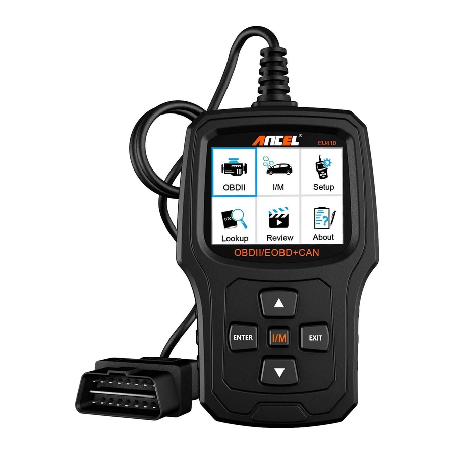
Tool Description - ANCEL EU410

- LCD DISPLAY - Indicates test results. 2.4" TFT 262K true color, 320*240 QVGALCD display.
- ENTER BUTTON - Confirm a selection (or action) from a menu.
- EXIT BUTTON - Cancel a selection (or action) from a menu or returns to the menu.
- UP SCROLL BUTTON - Up roll item by item in a menu.
- DOWN SCROLL BUTTON - Down roll item by item in a menu.
- "I/M" BUTTON - Quick State Emissions readiness check and drive cycle verification.
![]()
Remarks:
MIL Yellow - Dashboard MIL ON
MIL Gray - Dashboard MIL OFF
![]() - not support
- not support
![]() - complete
- complete
![]() - not complete
- not complete - OBDII CONNECTOR - Connects the scan tool to the vehicle 's Data Link Connector (DLC).

 - not support
 - complete
 - not complete
Specifications
- Display: 2.4" TFT 262K true color
- Operating Temperature: 0 to 50°C (32 to 140 F°)
- Storage Temperature: -20 to 70°C (-4 to 158 F°)
- External Power: 8.0 to 18.0 V power provided via vehicle battery
- Dimensions: 124x77.4x23.5mm
- Weight: 0.35kg
Accessories Included
- User's Manual - Instructions on too operations.
- USB cable - Used to upgrade the scan tool.
DTC Lookup
The DTC Lookup function is used to search for definitions of Code stored in the built-in Code library.
- From the Main Menu, use the UP/DOWN scroll button to select the Code Lookup and press the ENTER button.
![]()
Query the fault code, press enter + up, the cursor to the left; press enter + down, the cursor to the right.- For manufacturer specific codes, you'll need to select a vehicle make on an additional screen to look for DTC definitions.
- If definition could not be found (SAE or Manufacturer Specific), the scan tool displays "DTC definition not found! Please refer to vehicle service "manual!"
- Press the EXIT button and return to the main menu.

Review
This function is used to review the recorded DTC. Select [Review] menu and press ENTER button. The screen displays as follow:

Tool Setup
The scan tool allows you to make the following adjustments and settings:

- Select Language: Select the desired language.
- Unit of Measure: Set measure to English or Metric.
- Beep Set: Turns ON/OFF beep.
- Record: ON/OFF the Record.
- Feedback.
Review&Print diagnostic reports
- Download upgrade file from ANCEL website.
- The device is connected with computer through USB cable.
- Open the "update" application.
![]()
- Click "Review&Print" and automatically generate diagnostic reports.
![]()
![]()


About
Choose [About] and it displays as follow:

I/M
Choose [I/M]and it displays as follow:

OBDII Diagnostics

Don't connect or disconnect any test equipment with ignition on or engine running.
- Turn the ignition off.
- Locate the vehicle's 16-pin Data Link Connector (DLC).
- Plug the scan tool cable connector into the vehicle's DLC.
- Turn the ignition on. Engine can be off or running.
- Press ENTER to enter Main Menu. UP /DOWN button to select Diagnostics from the menu.
![]()
- Press ENTER to confirm.

If "LINKING ERROR!" message shows on the display.
- Verify that the ignition is ON;
- Check if the scan tool's OBDII connector is securely connected to the vehicle's DLC;
- Turn the ignition 'off' and wait for about 10 seconds. Turn the ignition back to 'on' and repeat the procedure from step 5.
- Vehicles that comply with the OBD2 protocols support these features:
[Read codes], [Erase codes], [Data stream], [Vehicle information].
![]()
- Whether the menu function can read the relevant data, the situation of different brand vehicles is different, subject to actual test. [IM Readiness, Freeze frame, O2 Sensor test, On-Board monitoring, Evap system test]
For example 1: Freeze frame refers to the moment when the fault occurs, some of the most important parameter values of the engine. When the vehicle has a fault code, the device displays the following menu prompts:
![]()
When the vehicle has no fault code, the device displays the fol owing menu prompts:
![]()
For example 2: [Evap System Test]Function: The Evaporative Emission Control System (EVAP) is used to prevent gasoline vapors from escaping into the atmosphere from the fuel tank and fuel system. OBDIl monitors the vehicle's EVAP system, the device sends a signal, different vehicles will respond differently.- When the vehicle supports the EVAP test, the device displays the following menu prompts:
![]()
- When the vehicle does not support the EVAP test, the device displays the following menu prompts:
![]()
- When the vehicle supports the EVAP test, the device displays the following menu prompts:


Read codes
- stored emission-related codes is hard codes which illuminate malfunction indicator lamp(MIL).
- pending codes is current codes or historical codes which will not illuminate malfunction indicator(MIL).
- Select OBDII in Main Menu and press ENTER, shown as follow:
![]()
- Press ENTER to the Diagnostic Menu, screen will display as follow:
![]()


Read Codes
- Select Read Codes and press ENTER in Diagnostic Menu. If there are some codes, the screen will display the codes as shown below:
![]()
- According to the above figure to select different item by pressing UP or DOWN and press ENTER to confirm.
![]()
- After viewing al the codes, you can press EXIT to return to the previous menu.


Erase Codes
- Select Erase Codes, the screen will display the interface as shown below. Press ENTER to erase DTC's, and the screen will display the interface as shown below:
![]()
- According to the above figure to press ENTER and the screen will display the interface as shown on the next page:
![]()


Notes:
- Before performing this function, make sure to retrieve and record the trouble codes.
- After clearing, you should retrieve trouble codes once more or turn ignition on and retrieve codes again. If there are still some trouble codes in the system, please troubleshoot the codes using a factory diagnosis guide, then clear the codes and recheck.
I/M Readiness
Select I/M Readiness and press ENTER, the screen will display the interface as shown below:

I/M readiness is to test Misfire / Fuel system / Comprehensive component, You can use UP or DOWN button to select and press ENTER, shown as follow:

N/A means not available on this vehicle, INC means incomplete or not ready, OK means Completed or Monitor Ok.
Data Stream
Press UP or DOWN button to select Data Stream in Main Menu interface and then press ENTER button to confirm, the screen will display the interface as shown below:

Select [View All Items] and press ENTER button, the screen will display the interface as shown below:

Scroll page, press up to last page, or press down to next page.
Select one, press [ENTER] to display the details.
Choose [select items] and press enter button. After that, press enter button again, shown as follow:

Scroll page, press enter + up, to previous page, press enter + down, the next page.
After selected items and press exit, the screen will display as follow:

Scroll page, press up to last page, or press down to next page.
If you want to know means of the abbreviation data, you can press the ENTER Button, the screen will display the interface as shown below.

Select [View Graphic terms] in Data stream menu and press ENTER, the screen will display the interface as shown below:

Scroll page, press enter + up, to previous page, press enter + down, the next page. Press enter button again to choose.
Press EXIT to return to display:

Max lines is 3.
Press EXIT to return to previous menu.
You can view all data stream items or select a certain item of live data with a graph.
View Freeze Frame
When an emission-related fault occurs, a snapshot of current vehicle parameter are recorded by the ECU.
Note: if DTCs were erased, Freeze Data may not be stored in vehicle.
Select Freeze Frame in main menu interface, the screen will display the interface as shown below:

You can use UP/ DOWN button to view the data. Press EXIT to return to Diagnostic Menu.
O2 sensor test
OBDII regulations set by the SAE require that relevant vehicles monitor and test the oxygen (O2) sensors to identify problems related to fuel
efficiency and vehicle emissions. These tests are not on-demand tests and they are done automatically when engine operating conditions are
within specified limits. These test results are saved in the on-board computer's memory.
The O2 Sensor Test function allows retrieval and viewing of O2 sensor monitor test results for the most recently performed tests from the vehicle's on-board computer.
The O2 Sensor Test function is not supported by vehicles which communicate using a controller area network (CAN). For O2 Sensor Test
results of CAN-equipped vehicles, see chapter "On-Board Mon. Test".
Select O2 Sensor Test in Diagnostic menu and press ENTER and the Screen will display as shown below (Data will be different every time):

On-board monitor test
This function can be utilized to read the results of on-board diagnostic monitoring. Tests for specific components/systems.
Select On-board Monitoring in Diagnostic Menu and press ENTER and the screen will display as shown below (Data will be different every time):

You can use up or DOWN button to select an item and press ENTER, the screen will display as shown below (Data Will be different every time):

Press EXIT to return to Diagnostic Menu.
EVAP System Test
The EVAP test function lets you initiate a leak test for the vehicle's EVAP system. The scanner does not perform the leak test, but signals to vehicle's on-board Computer to initiate the test. Before using the system test function, refer to the vehicle's service repair manual to determine the procedures necessary to stop the test.
Select EVAP System Test and press ENTER, the screen will display the relative information about EVAP system. Some vehicle manufacturers do not allow External devices to control vehicle system. If the car supports this function, it will display as below:

Vehicle Info
Select [Vehicle Info] and press ENTER, the screen will display the information, such as VIN (Vehicle identification Number), CID (Calibration ID) and CVN (Calibration verification number), as shown below (different cars will shown different data):

Press EXIT to return to Diagnostic Menu.
Update
The device is connected with computer through USB cable.

- When upgrade the device software, it only supports window 7/8/10 system.
- It can be updated directly on Windows 8 and Windows 10 system.
- When the computer is Windows 7 system, the device's software driver is installed on the computer.
The 64-bit operating system select "X64_64bit_win7" files
The 32-bit operating system select "X86 32bit win7" files
![]()
Note: the detail operation method, please view the [Help.avi] file.

Feedback
- When the [OBDII] function shows connected error with vehicle, please using the feedback function.
Choose [Feedback] and it displays as follow:
![]()
Choose (Start recording) to open record function and it displays as follow:
![]()
Next: Press EXIT Button and return to the main menu.
Choose [OBDII] menu to detecting again and it will record the data. - Transfer data to your computer and generate feedback file.
Download upgrade file on the computer from ANCEL website.
The device is connected with computer through USB cable.
![]()
Choose "Update" file and it displays as follow:
![]()
Click "Feedback" and it displays as follow:
![]()
Please send the feedback.bin file to support@anceltech.com.


Safety Precautions and Warnings
To prevent personal injury or damage to vehicles and/or the scan tool, read this instruction manual first and observe the following safety precautions whenever working on a vehicle:
- Tum the ignition off first, connect 16-pin to plug, then turn the ignition.
- Always perform automotive testing in a safe environment.
- DO not attempt to operate or observe the tool while driving a vehicle. Operating or observing the tool will cause driver distraction and could cause a fatal accident.
- Wear safety eye protection that meets ANSI standards.
- Keep clothing, hair, hands, tools, test equipment, etc away from al moving or hot engine parts. Operate the vehicle in a well ventilated place: Exhaust gases are Poisonous.
- Put blocks in front of the drive wheels and never leave the vehicle unattended while running tests.
- Use extreme caution when working around the ignition coil, distributor cap, ignition wires and spark plugs. These components create hazardous voltages when the engine is running.
- Put the transmission in PARK (for automatic transmission) or NEUTRAL (for manual transmission) and make sure the parking brake is engaged.
- Keep a fire extinguisher suitable for gasoline/chemical/electrica fires nearby.
- Don't connect or disconnect any test equipment while the ignition is on or the engine is running.
- Keep the scan tool dry, clean, free from oil/water or grease. Use a mild detergent on a clean cloth to clean the outside of the scan tool, when needed.
Service Procedures
If you have any questions, please contact your local store distributor.
If it becomes necessary to return the scan tool for repair, contact your local distributor for more information.
Documents / ResourcesDownload manual
Here you can download full pdf version of manual, it may contain additional safety instructions, warranty information, FCC rules, etc.
Advertisement


Need help?
Do you have a question about the EU410 and is the answer not in the manual?
Questions and answers