Table of Contents
Advertisement
Quick Links
LINC-MATIC CB
SAFETY INSTRUCTIONS FOR OPERATING AND MAINTENANCE
SAFETY INSTRUCTIONS FOR OPERATING AND MAINTENANCE
LINC-MATIC CB-LM: AS-PM-95240600 - AS-PM-95240601 - AS-PM-95240602 - AS-PM-95240603
LINC-MATIC CB-LM: AS-PM-95240600 - AS-PM-95240601 - AS-PM-95240602 - AS-PM-95240603
LINC-MATIC CB-LF: AS-PM-95240610 - AS-PM-95240611 - AS-PM-95240612 - AS-PM-95240613
LINC-MATIC CB-LF: AS-PM-95240610 - AS-PM-95240611 - AS-PM-95240612 - AS-PM-95240613
ISSUE
: EN
REVISION
: B
DATE
: 05 - 2021
BOOM
LM-LF
B-series
Instruction manual
REF : 8695 6060
Original instructions
Advertisement
Table of Contents

Related Manuals for Lincoln Electric LINC-MATIC CB LM B Series


Summary of Contents for Lincoln Electric LINC-MATIC CB LM B Series
- Page 1 BOOM LINC-MATIC CB LM-LF B-series SAFETY INSTRUCTIONS FOR OPERATING AND MAINTENANCE SAFETY INSTRUCTIONS FOR OPERATING AND MAINTENANCE LINC-MATIC CB-LM: AS-PM-95240600 - AS-PM-95240601 - AS-PM-95240602 - AS-PM-95240603 LINC-MATIC CB-LM: AS-PM-95240600 - AS-PM-95240601 - AS-PM-95240602 - AS-PM-95240603 LINC-MATIC CB-LF: AS-PM-95240610 - AS-PM-95240611 - AS-PM-95240612 - AS-PM-95240613 LINC-MATIC CB-LF: AS-PM-95240610 - AS-PM-95240611 - AS-PM-95240612 - AS-PM-95240613 ISSUE : EN...
- Page 2 Thank you very much for the trust you have shown by choosing this piece of equipment. It will give you trouble-free service if it is used and maintained as recommended. Its design, component specifications and manufacturing are in accordance with applicable European directives.
-
Page 3: Table Of Contents
Table of contents A - IDENTIFICATION ........................1 B - SAFETY INSTRUCTIONS ......................2 1 - Particular safety instructions --------------------------------------------------------------------------- 2 C - DESCRIPTION ......................... 5 1 - Description ---------------------------------------------------------------------------------------------------- 5 2 - Type of boom ------------------------------------------------------------------------------------------------- 5 3 - Column (ref.: F) ---------------------------------------------------------------------------------------------- 6 4 - Lifting (ref.: R) ------------------------------------------------------------------------------------------------ 6 5 - Sliding block (ref: C) --------------------------------------------------------------------------------------- 6 6 - Powered carriage (ref: M) -------------------------------------------------------------------------------- 6... - Page 4 9 - Column rotation maintenance -------------------------------------------------------------------------33 10 - Carriage maintenance ----------------------------------------------------------------------------------34 11 - Troubleshooting ------------------------------------------------------------------------------------------36 12 - Spare parts -------------------------------------------------------------------------------------------------37 PERSONAL NOTES ........................46 INFORMATION DISPLAYS AND PRESSURE GAUGES Measurement instruments or displays of voltage, intensity, speed, accuracy etc. are to be considered as indicators, whether they are analogue or digital.
-
Page 5: A - Identification
A - IDENTIFICATION The information below should be provided in all correspondence. User’s guide... -
Page 6: B - Safety Instructions
Before use, the operator must make sure that there is no risk of collision with personnel. Clean the working area from time to time. This machine may only be moved by its designer, namely Lincoln Electric. Never modify the machine. - Page 7 Store cable bundles behind the electrical cabinet of the boom. The use of Personal Protective Equipment (PPE) is mandatory. Machine maintenance must be carried out with all the energy supplies switched off. The disconnection and padlocking of all energy sources is mandatory. Sliding block maintenance may only be carried out with all the energy supplies switched off, when the covers are removed.
- Page 8 Make sure that no part of the machine can come within less than 500 mm of an obstacle according to the safety standards NF EN 349. Important: the operator passage way must absolutely be clear over a minimum width of 800 mm according to safety standards NF EN 547-1-3.
-
Page 9: C - Description
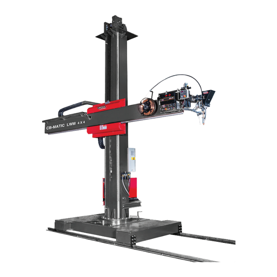
C - DESCRIPTION 1 - Description This welding boom dedicated to Submerged Arc (SA) welding makes it possible to position and move an automatic welding head. It is particularly designed for fabricating cylindrical bodies and also metal structures. 2 - Type of boom The boom is available in: “LINC-MATIC CB-LF”... -
Page 10: Column (Ref.: F)
3 - Column (ref.: F) It is made up of bent mechanically welded metal. Two rolling tracks over the entire height ensure stable and smooth vertical movement of the arm support sliding block. The column has a vertical rack over its entire height, which acts as safety gear if the lifting system fails. It is fixed to the carriage or the base by means of a slewing ring with a large diameter. -
Page 11: Electrical Cabinet (Ref: A)
9 - Electrical cabinet (ref: A) The electrical cabinet powers all the boom functions. Power to the welding equipment (welding power source) and the outside shafts (rotator, positioner etc.) is not supplied from this cabinet, but by a power supply outside the boom. -
Page 12: Dimensions And Travel Ranges Of Linc-Matic Cb-Lm Boom
11 - Dimensions and travel ranges of LINC-MATIC CB-LM boom 1525 360° 1480 2600 2010 3080 1800 12 - Dimensions and travel ranges of LINC-MATIC CB-LF boom 1525 360° 1480 1800 1800 LINC-MATIC CB ‘B-series’... -
Page 13: Technical Specifications
Vertical Horizontal Height Part number Type travel travel Weight (kg) (mm) “H” (mm) “Y” (mm) “X” AS-PM-95240600 LINC-MATIC CB-LM 3032B 3000 3200 5500 4900 AS-PM-95240601 LINC-MATIC CB-LM 4042B 4000 4200 6500 5200 AS-PM-95240602 LINC-MATIC CB-LM 5052B 5000 5200 7550 5500 AS-PM-95240603 LINC-MATIC CB-LM 6062B 6000 6200... -
Page 14: D - Assembly And Installation
D - ASSEMBLY AND INSTALLATION 1 - Installation conditions The machine must be located in accordance with safety standard NF EN 547 -1 -3 to keep personnel safe. The following conditions must be fulfilled before the equipment is installed. ELECTRICITY SUPPLY see electrical diagram supplied VERY IMPORTANT The power cable (customer supply) must have a section suitable for the power rating of the installation. -
Page 15: Floor Preparation
2 - Floor preparation The floor does not need any particular preparation for installing the machine; however, we recommend a concrete floor for the machine to be satisfactorily stable. Thickness of concrete slab: 200mm • Flatness over the entire area: ± 5mm •... - Page 16 Column The column is to be lifted with two pieces of lifting equipment to avoid the pendulum effect. LINC-MATIC CB LM-LF 3032B : 2500 daN LINC-MATIC CB LM-LF 4042B : 2750 daN LINC-MATIC CB LM-LF 5052B : 3050 daN LINC-MATIC CB LM-LF 6062B : 3300 daN LINC-MATIC CB LM-LF 3032B : 580 daN LINC-MATIC CB LM-LF 4042B : 690 daN LINC-MATIC CB LM-LF 5052B : 810 daN...
- Page 17 Carriage Base 1200 daN 1500 daN Platform Guide rails LW rail (10 metres): : 260daN • 150 daN LE rail (6 metres): 150 daN • Burback rail (6 metres): 260 daN • Electrical cabinet 50 daN Operator protection: Helmet - Gloves - Safety shoes User’s guide...
-
Page 18: Installation On The Ground Of A Linc-Matic Cb Lm And
4 - Installation on the ground of a LINC-MATIC CB LM and LF 1 - Installation on rails (LINC-MATIC CB LM) Mark and drill the anchor locations. LW rail 1800 1338 1800 1000 1000 10000 LE rail 1800 1370 1800 1450 1450 6000... - Page 19 Burbach rail 1800 1330 1800 1000 1000 6000 2 - Installation of the base (LINC-MATIC CB LF) Mark and drill the anchor location as shown in the layout drawing. M16 x 175 M16 x 175 User’s guide...
-
Page 20: Dimensions Of The Linc-Matic Cb Boom
5 - Dimensions of the LINC-MATIC CB boom Before use, the operator must make sure that there is no risk of collision with personnel. While reassembling a LINC-MATIC CB LM boom, first position and anchor the tracks on the floor, place the carriage on the rails, making sure the flanged wheels are between the rails. - Page 21 Install the 2 column locking systems with the 2 M16 x 65 hex head screws each. Lock the rotation of the column Fill the lifting reducer with oil up to the level, i.e. approximately 4.5 litres. We recommend using oil For safety reasons, the reducer is supplied with no oil.
- Page 22 Make sure that the arm is level using a level placed on the arm rail. If the parallel alignment and levelling is not correct, the eccentric rollers must be adjusted; please contact the After-Sales Service department of Lincoln Electric LINC-MATIC CB ‘B-series’...
-
Page 23: Reassembling The Platform And The Electrical Cabinet
6 - Reassembling the platform and the electrical cabinet Install the platform with 4 M 12 X 35 hex head screws. Check that the platform is horizontal and fully supported by the column reinforcements. Install the electrical cabinet with 4 M8 X 50 hex head screws. The cabinet is fixed onto the two support bars mounted on the column. -
Page 24: Installing The Cable Drag Chain Of The Column
8 - Installing the cable drag chain of the column Assemble the vertical cable drag chain C2 on the duct G1 and the vertical duct G3 (the vertical duct on the column is already assembled); to do so, prepare the bundles, air hoses and welding cables on the floor in the open cable drag chain. -
Page 25: E - Operating Manual
E - OPERATING MANUAL 1 - Control buttons on cabinet Power on indicator Carriage speed display option (only on LINC-MATIC CB LM) Carriage speed setting potentiometer (only on LINC-MATIC CB LM) Powering up Main machine disconnector User’s guide... -
Page 26: Control Buttons On Operator Console
2 - Control buttons on operator console Welding head control console Remote control (15 metre bundle outside the cable drag chain) (3 metre bundle) Arm speed setting potentiometer Head slide up/down movement Head slide left/ right movement Emergency stop Arm speed display Boom arm left right movement Boom up/down movement Powering up... -
Page 27: 3- Starting Up And Shutting Down
3- Starting up and shutting down REMINDER: The operator station is located before the control console. The machine is designed to work with only one operator. POWERING UP: Set the disconnector E5 to the position I; the indicator E1 will go on. •... -
Page 28: Starting A Welding Cycle
4 - Starting a welding cycle To execute movements and/or cycles, refer to the instructions of the associated welding equipment. 5 - Welding cycle diagram There are two modes for starting a welding cycle with the arm movement: Contact striking ... - Page 29 User’s guide...
-
Page 30: F - Maintenance
Lincoln Electric personnel. The removal and/or replacement of mechanical components of the LINC-MATIC CB boom are FORBIDDEN. Contact the After-Sales Service department of Lincoln Electric. LINC-MATIC CB ‘B-series’... -
Page 31: Maintenance Schedule
Body and Guide Visual Cleaning worm *: Contact the After-Sales Service department of Lincoln Electric **: Immediate inspection in the event of an impact We recommend putting in place a traced system for tracking all your maintenance operations. User’s guide... -
Page 32: Lifting System Maintenance
3 - Lifting system maintenance Step Operation Brake Periodic inspection by the Maintenance department of the working of the brake Step Operation Reduction gear The geared motors must be maintained to offer maximum efficiency by carrying out the scheduled maintenance operations recommended by their manufacturers. - Page 33 Step Operation Chain Visual inspection No corrosion → if corroded, the chain must be changed. • Flexibility: no stiffness or seizing of articulations → if not flexible, the chain must • be changed Cleanliness: no fouling or build-up of grease and dust → if the chain is fouled, •...
-
Page 34: Maintenance Of Safety Gear
If it is not blocked, the safety gear is not working. Contact the After-Sales • Service department of Lincoln Electric To release the block, lift the arm again with the webbing • Raise the arm using the control buttons till the webbing is no longer taut and •... -
Page 35: Sliding Block Maintenance
Step Operation Rotation brake Inspect operation. 6 - Sliding block maintenance Step Operation Roller After removing the covers of the sliding block, check the condition of the rollers (=> clean, with no damage). User’s guide... -
Page 36: Arm Maintenance
7 - Arm maintenance Step Operation Rack Brush the toothed side without adding grease. To avoid oxidation, you may apply sliding varnish of the type: Adermos 800 (Molydal) Step Operation Rail Check the condition of the rails (=> clean, with no foreign body). To avoid oxidation, you may apply sliding varnish of the type: ... -
Page 37: Column Rotation Maintenance
Step Operation Reduction gear After taking off the covers of the sliding block, carry out the following checks: visually for leaks. • visually check the overall condition of the reduction gear • 9 - Column rotation maintenance Step Operation Reduction gear ... -
Page 38: Carriage Maintenance
10 - Carriage maintenance Step Operation Bearing housing After taking off the guard covers, lubricate the bearings. ESSO BEACON EP2 Step Operation Reduction gear After taking off the guard cover, verify: visually for leaks. • visually check the overall condition of the reduction gear •... - Page 39 Step Operation Clamp The clamps must not rub against the rails. The clamps must be positioned correctly 5 mm from the rail in all directions. Step Operation Clamp Check the fastening of the clamps and the presence of pins. Tightening torque 50 Step Operation Body and worm...
-
Page 40: Troubleshooting
11 - Troubleshooting Problem Cause Solution Incorrect operation of arm, lifting Limit switch triggered Adjust the position or rotation Motor overload Verify the reduction gear Variable drive malfunction Verify the variable drive Motor malfunction Verify the motor Contactor or relay malfunction Replace the contactor or relay Transformer malfunction Verify the transformer... -
Page 41: Spare Parts
12 - Spare parts Ordering procedure: Almost all the parts of a machine or installation are referenced in the photographs and sketches. The descriptive tables contain three types of item: items normally held in stock: • items not held in stock: •... -
Page 42: Electrical Cabinet
Electrical cabinet 1-11 2&4 1-10 SBES1 HLES LINC-MATIC CB ‘B-series’... - Page 43 normally held in stock. not in stock upon request. Ref. Part no Stock Order Description 3P- 6A motor circuit breaker AS-PS-T0300000 Transformer, 380VAC/24VAC - 200VA AS-PS-T0300001 Transformer, 400VAC/5VDC - 1A KM1-4 LC1D09B7 contactor LC1D32B7 contactor Additive contact, LADN40 Safety module, XPSAC5121 KA1-10 Relay, 24VAC - 3A - 250V 25A disconnector...
- Page 44 Sliding block normally held in stock. not in stock upon request. Ref. Part no Stock Order Description Motor Reduction gear Pinion Complete limit switch (arm) Sliding block roller assembly (arm and column) Lateral guide roller Support roller • While ordering parts, please indicate the quantity and note the number of your machine in the box above. TYPE: Number: LINC-MATIC CB ‘B-series’...
- Page 45 Lifting normally held in stock. not in stock upon request. Ref. Part no Stock Order Description Motor AS-PS-T0300008 Reducer (for boom LINC-MATC CB LM-LF 3032 and 4042) AS-PS-T0300012 Reducer (for boom LINC-MATC CB LM-LF 5052 and 6062) Bearing housing Bearing Motor shaft pinion Idle pinion...
- Page 46 Rotation normally held in stock. not in stock upon request. Ref. Part no Stock Order Description Notched ring Pinion Motor Reduction gear Rotation indexing • While ordering parts, please indicate the quantity and note the number of your machine in the box above. TYPE: Number: LINC-MATIC CB ‘B-series’...
- Page 47 Carriage normally held in stock. not in stock upon request. Ref. Part no Stock Order Description Motor Reduction gear Drive pinion Carriage shaft ring Bearing housing Flanged wheel Drive shaft Idle shaft • While ordering parts, please indicate the quantity and note the number of your machine in the box above. TYPE: Number: User’s guide...
- Page 48 Slide and laser spotlight normally held in stock. not in stock upon request. Ref. Part no Stock Order Description AS-PS-T0300009 Complete slide AS-PS-T0300010 Motor + slide reducer AS-PS-T0300011 Limit switch (x2) AS-WP-95092920 Laser spotlight + 30 m bundle • While ordering parts, please indicate the quantity and note the number of your machine in the box above.
- Page 49 User’s guide...
-
Page 50: Personal Notes
PERSONAL NOTES Lincoln Electric France S.A.S. Avenue Franklin Roosevelt 76120 Le Grand Quevilly 76121 Le Grand Quevilly cedex www.lincolnelectriceurope.com LINC-MATIC CB ‘B-series’...
Need help?
Do you have a question about the LINC-MATIC CB LM B Series and is the answer not in the manual?
Questions and answers