Advertisement
Quick Links
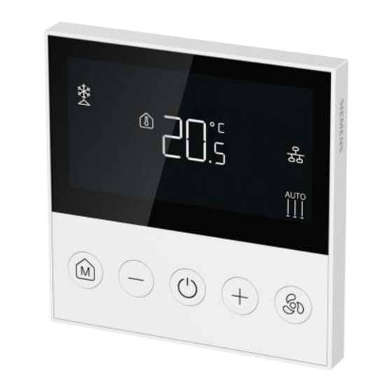
Fan coil room thermostat (Modbus RTU server)
RDQ411MB
A6V15081400_en--_a
2024-09-18
For 2-pipe and 4-pipe fan coil units
●
Support of communication protocol 'Modbus RTU server'
●
One multi-functional input (X1) for keycard contact or external sensor
●
LCD backlit display and keylock function
●
Operating mode button: Comfort, Protection, and Economy (3-second long-press
in Comfort)
●
'M' button:
– For 2-pipe applications: Heating, cooling, ventilation
– For 4-pipe applications (auto): Automatic heating/cooling changeover,
ventilation
– For 4-pipe applications (manual): Heating, cooling, ventilation
●
3-speed fan control (automatic or manual) via fan button
●
Display of either room temperature, setpoint or bus temperature
●
Support of Chinese standard conduit boxes (max. 78 × 78) ≥ 45 mm (±2) deep
and British metal standard conduit boxes (max. 75 × 75) ≥ 47 mm (±2) deep
●
Adjustable commissioning and control parameters
智能基础设施集团
Advertisement

Related Manuals for Siemens RDQ411MB


Summary of Contents for Siemens RDQ411MB
- Page 1 Fan coil room thermostat (Modbus RTU server) RDQ411MB For 2-pipe and 4-pipe fan coil units ● Support of communication protocol ‘Modbus RTU server’ ● One multi-functional input (X1) for keycard contact or external sensor ● LCD backlit display and keylock function ●...
- Page 2 Mounting bracket to fit onto a square conduit box with Chinese standard conduit boxes (max. 78 × 78) ≥ 45 mm (±2) deep and British metal standard conduit boxes (max. 75 × 75) ≥ 47 mm (±2) deep. Siemens A6V15081400_en--_a Smart Infrastructure...
- Page 3 "timer with delay Off" mode. Fan button for: Enter parameter setting ● Fan speed selection ● Screen unlock (press and hold down the button for 3 seconds) Operating mode The following operating modes are available: Siemens A6V15081400_en--_a Smart Infrastructure 2024-09-18...
- Page 4 Type summary Product no. Stock Operating Control outputs Multi- Description voltage type functional input On/Off On/Off (3- Sensor wire) speed card √ √ √ √ √ RDQ411MB S55770 AC 230 V Room -T518 thermostat Modbus Siemens A6V15081400_en--_a Smart Infrastructure 2024-09-18...
- Page 5 Ordering When ordering, specify both product number / stock number and name: e.g., RDQ411MB / S55770-T518 Room thermostat Modbus. Order valve actuators and external sensors separately. Equipment combinations On/Off actuators Type of units Product number Data sheet* Electromotive On/Off valve and MVI.../MXI...
- Page 6 (Document ID: A6V15113831 ) enclosed with the thermostat. WARNING Device damage Carefully read all wiring diagrams prior to installation to avoid damage to the device caused by incorrect wiring of high or low voltages. Siemens A6V15081400_en--_a Smart Infrastructure 2024-09-18...
- Page 7 When the internal sensor is not working properly, is displayed. The thermostat enters Protection mode. When P30 is set to 1 but the external sensor is broken or not connected, is displayed, and the thermostat continues to work on the internal sensor. Siemens A6V15081400_en--_a Smart Infrastructure 2024-09-18...
- Page 8 1 = Setpoint 2 = Bus temperature Minimum setpoint in Comfort 5 °C 5 °C...P10 (not included) Maximum setpoint in Comfort 35 °C P09 (not included) ...40 °C Heating setpoint in Economy 15 °C Off, 5 °C...WcoolEco Siemens A6V15081400_en--_a Smart Infrastructure 2024-09-18...
- Page 9 “---” is displayed for 3 seconds while reloading Device address 1...247 Baud rate 0 = 4800 bps 1 = 9600 bps 2 = 19200 bps 3 = 38400 bps Parity 0 = Odd 1 = Even Siemens A6V15081400_en--_a Smart Infrastructure 2024-09-18...
- Page 10 Delete all personal data and dispose of the item(s) at separate collection and recycling facilities in accordance with local and national legislation. For additional details, refer to Siemens information on disposal. Open source software (OSS) Software license overview...
- Page 11 => 'Siemens Security Advisories' Warranty Technical data on specific applications are valid only together with Siemens products listed under "Equipment combinations". Siemens rejects any and all warranties in the event that third-party products are used. Siemens...
- Page 12 4800, 9600, 19200 (default), 38400 Device address 1...247, 1 (default) Cable length Max. 1200 meters Identity Server Start bit Data bits Parity 0 = Odd 1 = Even (default) 2 = No parity Stop bit Siemens A6V15081400_en--_a Smart Infrastructure 2024-09-18...
- Page 13 Storage as per EN 60721-3-1 Temperature: -5...+50 °C ● Ambient humidity: 5...95 % r.h. (non- condensing) ● Transport (packaged for transport) as per Temperature: -25...+70 °C EN 60721-3-2 ● Ambient humidity: 5...95 % r.h. (non- Siemens A6V15081400_en--_a Smart Infrastructure 2024-09-18...
- Page 14 (A5W01944065A*) contains data on environmentally compatible product design and assessments (RoHS compliance, materials composition, packaging, environmental benefit, disposal). *) All documentation can be downloaded from www.siemens.com/bt/download. General Weight (Without box and user document) 168 g Color of housing White RAL9016...
- Page 15 Multi-functional input for temperature sensor (e.g. QAH11.1) or potential-free switch (keycard) Measuring neutral for sensor and switch RS485 Modbus connection RS485 Modbus connection RS485 signal/common ground (differential common) Connection diagrams 2-pipe application, X1 connects external sensor 2-wire valve 3-wire valve Siemens A6V15081400_en--_a Smart Infrastructure 2024-09-18...
- Page 16 2-pipe application, X1 connects external switch 2-wire valve 3-wire valve 4-pipe application, X1 connects external sensor or keycard contact Siemens A6V15081400_en--_a Smart Infrastructure 2024-09-18...
- Page 17 2-pipe fan coil unit On/Off (heating or cooling) Heating/cooling valve actuator 3-speed fan Thermostat 4-pipe fan coil units 4-pipe fan coil unit On/Off (heating and cooling) Heating or heating/cooling valve actuator Cooling valve actuator 3-speed fan Thermostat Siemens A6V15081400_en--_a Smart Infrastructure 2024-09-18...
- Page 18 X1 (DI) 0012 0x04 0 = Off 1 = On Fault information 0013 0x04 0: No alarm Any bit set to 1 stands for an alarm or error defined as follows Bit0: (BUS) communication error Siemens A6V15081400_en--_a Smart Infrastructure 2024-09-18...
- Page 19 P15 / Fan control 0009 0x03 0x06 0 = Fan off deadzone in Comfort 1 = Fan speed 1 P16 / Fan operations 0010 0x03 0x06 0 = Disable 1 = Enable Siemens A6V15081400_en--_a Smart Infrastructure 2024-09-18...
- Page 20 × 50 -20...70 °C Heating/cooling/ventilatio 0106 0x03 0x06 0 = Heating n changeover 1 = Cooling 2 = Ventilation System time 0201 0x03 0x10 0000 hhmm 0202 h 0...23 = Hours m 0...59 = Minutes Siemens A6V15081400_en--_a Smart Infrastructure 2024-09-18...
- Page 21 0x03---Read holding (RO) registers proce 0x04---Read input Read/ registers Write 0x06---Write single (R/W) register 0x10---Write multiple registers Restart device 0203 0x03 0x06 0 = Off 1 = Restart Reserve1 0204 0x03 0x06 Reserve2 0205 0x03 0x06 Siemens A6V15081400_en--_a Smart Infrastructure 2024-09-18...
- Page 22 Dimensions (mm) Siemens A6V15081400_en--_a Smart Infrastructure 2024-09-18...
- Page 24 Issued by © Siemens 2024 Siemens Switzerland Ltd Technical specifications and availability subject to change without notice. Smart Infrastructure Global Headquarters Theilerstrasse 1a CH-6300 Zug +41 58 724 2424 www.siemens.com/buildingtechnologies Document ID A6V15081400_en--_a Edition 2024-09-18...
Need help?
Do you have a question about the RDQ411MB and is the answer not in the manual?
Questions and answers