Table of Contents
Advertisement
Quick Links
Advertisement
Table of Contents
Troubleshooting

Related Manuals for Stiga e-Ride C300


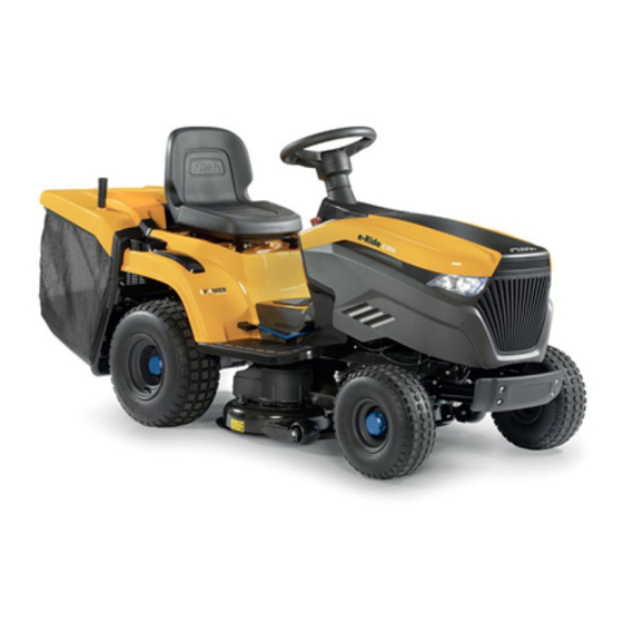
Summary of Contents for Stiga e-Ride C300
- Page 1 WORKSHOP MANUAL e-Ride C300 - C500...
-
Page 2: Introductory Notes
All mentioned brands, trade names, logos and trademarks belong to their respective owners. © by STIGA - Any use of the illustrations and any copying, reproduction or translation, even partial, of the texts in this document is prohibited without express authorisation. -
Page 3: Structure Of The Manual
WORKSHOP MANUAL CHAPTER PAGE e-Ride C300 - C500 INTRODUCTION 1. INTRODUCTION CONTENTS 1.1. GUIDE TO MANUAL CONSULTATION ......................3 1.1.1. LIMITATION OF LIABILITY .......................... 3 1.1.2. STRUCTURE OF THE MANUAL ......................... 3 1.1.3. SYMBOLS AND TERMS USED ........................4 1.2. WORK SAFETY REQUIREMENTS ........................5 1.2.1. - Page 4 WORKSHOP MANUAL CHAPTER PAGE e-Ride C300 - C500 INTRODUCTION 1.1.3. SYMBOLS AND TERMS USED a) Symbols Their function is to draw the operator’s attention, so that s/he can carry out the operations with the necessary care and caution. It indicates operations to be carried out with particular care so as not to compromise the operation and safety of the machine.
-
Page 5: Work Preparation
WORKSHOP MANUAL CHAPTER PAGE e-Ride C300 - C500 INTRODUCTION 1.2. WORK SAFETY REQUIREMENTS 1.2.1. OPERATORS’ QUALIFICATION All maintenance, disassembly and repair operations must be carried out by experienced mechanics who are familiar with all the safety and accident prevention rules, after reading the procedures in this manual. -
Page 6: Fault Signalling
WORKSHOP MANUAL CHAPTER PAGE e-Ride C300 - C500 INTRODUCTION 1.3. SERVICE CENTRE PROCEDURES 1.3.1. VALIDITY AND WORK UNDER WARRANTY The Manufacturer warranty will cover work carried out during the warranty period in the manner and within the limits of the existing contractual relations. -
Page 7: Table Of Contents
WORKSHOP MANUAL CHAPTER PAGE e-Ride C300 - C500 INFORMATION FOR SERVICE 2. INFORMATION FOR SERVICE CONTENTS 2.1. GENERAL INFORMATION ..........................8 2.1.1. IDENTIFICATION OF THE MACHINE AND MAIN COMPONENTS ............8 2.1.2. SAFETY PRINCIPLES TO IMPLEMENT ..................... 9 2.1.3. BASIC EQUIPMENT ........................... 10 2.1.4. -
Page 8: Information For Service
WORKSHOP MANUAL CHAPTER PAGE e-Ride C300 - C500 INFORMATION FOR SERVICE 2.1. GENERAL INFORMATION 2.1.1. IDENTIFICATION OF THE MACHINE AND MAIN COMPONENTS 1) Machine Each machine is supplied with a label (1) placed behind the seat indicating technical data, model and serial number. -
Page 9: Safety Principles To Implement
WORKSHOP MANUAL CHAPTER PAGE e-Ride C300 - C500 INFORMATION FOR SERVICE 2.1.2. SAFETY PRINCIPLES TO IMPLEMENT All machines are manufactured in accordance with the strict European safety regulations in force. In order to maintain the initial level of safety over time, it is advisable for the Service Centre to act accordingly, carrying out the necessary checks whenever the opportunity arises. -
Page 10: Basic Equipment
WORKSHOP MANUAL CHAPTER PAGE e-Ride C300 - C500 INFORMATION FOR SERVICE 2.1.3. BASIC EQUIPMENT All operations can be carried out with the tools normally available in a good Mechanical Workshop in the automotive sector. As far as the electrical and electronic parts are concerned, it is necessary to have suitable testers, as indicated specifically in chapter 7 of this manual. -
Page 11: Handling And Lifting Of The Machine
WORKSHOP MANUAL CHAPTER PAGE e-Ride C300 - C500 INFORMATION FOR SERVICE 2.1.4. HANDLING AND LIFTING OF THE MACHINE General information This chapter deals with the general aspects concerning the work to be carried out and the main rules to ensure successful operation and machine safety. - Page 12 WORKSHOP MANUAL CHAPTER PAGE e-Ride C300 - C500 INFORMATION FOR SERVICE Vertical positioning ATTENTION! This operation requires the intervention of two people; during lifting and overturning operations, hold the machine only from parts that offer the necessary solidity (steering wheel, frame, rear plate, etc.) and NEVER from the plastic parts of the body.
-
Page 13: Maintenance Work
WORKSHOP MANUAL CHAPTER PAGE e-Ride C300 - C500 INFORMATION FOR SERVICE 2.2. MAINTENANCE WORK 2.2.1. MAINTENANCE SCHEDULE The Instruction Manual foresees a series of interventions by the Customer to ensure basic maintenance and other operations that often require the intervention of more qualified staff. -
Page 14: Snap Ring Fitting
WORKSHOP MANUAL CHAPTER PAGE e-Ride C300 - C500 INFORMATION FOR SERVICE 2.2.3. SNAP RING FITTING The “Benzing” type snap rings (1) are characterised by one side with blunt edges and the other with sharp edges. In order to ensure maximum hold, it is necessary that the blunt side faces the element to be held (2), leaving the sharp edge side on the outside. -
Page 15: Crown-Shaped Fasteners
WORKSHOP MANUAL CHAPTER PAGE e-Ride C300 - C500 INFORMATION FOR SERVICE 2.2.5. CROWN-SHAPED FASTENERS Some trunnions (6) are fastened at the end by means of crown-shaped fasteners (7); these fasteners are damaged during disassembly losing all retaining capacity, therefore, they must never be reused. -
Page 16: Spare Parts
WORKSHOP MANUAL CHAPTER PAGE e-Ride C300 - C500 INFORMATION FOR SERVICE 2.3. SPARE PARTS 2.3.1. UNAUTHORISED SPARE PARTS Use only original spare parts. The use of a spare part not authorised by the Manufacturer may adversely affect the performance, life or safety of this machine and will void the Warranty. -
Page 17: Safety Device Control
WORKSHOP MANUAL CHAPTER PAGE e-Ride C300 - C500 INFORMATION FOR SERVICE 2.4. SAFETY DEVICE CONTROL 2.4.1. SAFETY SYSTEM TRIGGERING LOGIC Safety systems will be triggered in the following two cases: to prevent ignition if ALL safety conditions are not met;... -
Page 18: Technical Data And Dimensions
WORKSHOP MANUAL CHAPTER PAGE e-Ride C300 - C500 INFORMATION FOR SERVICE 2.5. TECHNICAL DATA AND DIMENSIONS 2.5.1. TECHNICAL DATA C300 C500 Electric system 48V – 30 Ah Li-Ion 48V – 40 Ah Li-Ion Battery pack 1.5 kWh 2 kWh 6.5 ÷ 7 h (220V) 8.5 ÷... -
Page 19: Removal Of External Parts And Main Units
WORKSHOP MANUAL CHAPTER PAGE e-Ride C300 - C500 BODYWORK FRAME AND COVERS 3. BODYWORK FRAME AND COVERS CONTENTS 3.1. REMOVAL OF EXTERNAL PARTS AND MAIN UNITS ..................19 3.1.1. FRONT BONNET REMOVAL ........................19 3.1.2. WHEEL COVER REMOVAL ........................20 3.1.3. -
Page 20: Wheel Cover Removal
WORKSHOP MANUAL CHAPTER PAGE e-Ride C300 - C500 BODYWORK FRAME AND COVERS 3.1.2. WHEEL COVER REMOVAL General information The wheel cover must be completely removed to replace the wheel and to access the seat microswitch, located under the crossbar supporting the two springs. - Page 21 WORKSHOP MANUAL CHAPTER PAGE e-Ride C300 - C500 BODYWORK FRAME AND COVERS The cover (13) is secured by means of: 2 screws (14) placed under the seat, 2 lower screws (15) (1 on each side) under the outer edge of the footrests, 2 lower screws (16) (1 on each side) with relevant washers (17) under the outer edge of the footrests.
- Page 22 WORKSHOP MANUAL CHAPTER PAGE e-Ride C300 - C500 BODYWORK FRAME AND COVERS Upon assembly, follow the procedures described above in reverse order. Pay attention to correctly reposition the hook (20) and correctly insert the two side tabs (21) of the cover into the seats in the footrests.
-
Page 23: Dashboard Removal
WORKSHOP MANUAL CHAPTER PAGE e-Ride C300 - C500 BODYWORK FRAME AND COVERS 3.1.3. DASHBOARD REMOVAL General information The dashboard needs to be removed only for its replacement. Tightening torques Reference: 11-12-13-14 Dashboard fixing screws 12 ÷ 15 Nm Procedure Using a screwdriver, release the central hooks (1) that secure the steering wheel cover (2). -
Page 24: Workshop Manual
WORKSHOP MANUAL CHAPTER PAGE e-Ride C300 - C500 BODYWORK FRAME AND COVERS Disconnect all electrical connectors from their respective components: connector to the push-button panel (7), emergency stop switch (8), connector to the enabling key (9), The dashboard (10) is secured by means of:... - Page 25 WORKSHOP MANUAL CHAPTER PAGE e-Ride C300 - C500 BODYWORK FRAME AND COVERS 2 lower side screws (13) (1 on each side) on the inside of the bonnet, moving the main wiring sheath out of the − screw seat, 2 lower screws (14) (1 on each side) that can be reached after removing the central cover.
-
Page 26: Adjustment And Set-Up
WORKSHOP MANUAL CHAPTER PAGE e-Ride C300 - C500 STEERING 4. STEERING CONTENTS 4.1. ADJUSTMENT AND SET-UP ..........................26 4.1.1. STEERING PLAY ADJUSTMENT ......................26 4.1.2. STEERING GEOMETRY ADJUSTMENT ....................27 4.2. REMOVAL OF EXTERNAL PARTS AND MAIN UNITS ..................28 4.2.1. -
Page 27: Steering Geometry Adjustment
WORKSHOP MANUAL CHAPTER PAGE e-Ride C300 - C500 STEERING 4.1.2. STEERING GEOMETRY ADJUSTMENT General information The correct steering geometry is given by the distance between the joints of the tie rod and wheel connection rod. Any anomalies due to impacts or accidental causes lead to a reduction in steering precision and increased tyre wear,... -
Page 28: Removal Of External Parts And Main Units
WORKSHOP MANUAL CHAPTER PAGE e-Ride C300 - C500 STEERING B) Steering wheel adjustment Make sure that the toe-in is correct (point «A») and align the front wheels. If the steering wheel is not straight, remove the joint (5) and screw or unscrew it on the tie rod (6) just as much as necessary. - Page 29 WORKSHOP MANUAL CHAPTER PAGE e-Ride C300 - C500 STEERING A) Removing the steering pinion and sprocket Unhook the clip (2) and lift the steering column (3) just as much to remove the pinion (4), taking care not to cause the pin (5) to come out.
-
Page 30: Troubleshooting
WORKSHOP MANUAL CHAPTER PAGE e-Ride C300 - C500 STEERING B) Replacing the lower bushing Unhook the clip (21) and lift the steering column (22) just as much to remove the pinion (23), taking care not to cause the pin (24) to come out. -
Page 31: Adjustment And Set-Up
WORKSHOP MANUAL CHAPTER PAGE e-Ride C300 - C500 WHEELS AND DRIVE UNIT 5. WHEELS AND DRIVE UNIT CONTENTS 5.1. ADJUSTMENT AND SET-UP ..........................31 5.1.1. TRACTION PEDAL ADJUSTMENT ......................31 5.2. REMOVAL OF EXTERNAL PARTS AND MAIN UNITS ..................33 5.2.1. - Page 32 WORKSHOP MANUAL CHAPTER PAGE e-Ride C300 - C500 WHEELS AND DRIVE UNIT Adjusting the pedal to the “neutral” position The operation consists in adjusting the position of the pedal (3) in relation to the lever (2) on the electrical unit to the maximum forward speed position by means of a spring.
-
Page 33: Removal Of External Parts And Main Units
WORKSHOP MANUAL CHAPTER PAGE e-Ride C300 - C500 WHEELS AND DRIVE UNIT 5.2. REMOVAL OF EXTERNAL PARTS AND MAIN UNITS 5.2.1. REAR AXLE REMOVAL General information The rear axle consists of a monoblock unit, which includes the traction motor, the drive and the differential. - Page 34 WORKSHOP MANUAL CHAPTER PAGE e-Ride C300 - C500 WHEELS AND DRIVE UNIT Remove the ties (2) and slide out the wires from the cable guide. Disconnect the signal cable (3). Disconnect the two power cables (4 - 5). Pull the cables out of the retainer (6), paying attention to the route.
- Page 35 WORKSHOP MANUAL CHAPTER PAGE e-Ride C300 - C500 WHEELS AND DRIVE UNIT The unit is supported on the rear right-hand side by a bracket (8). Loosen the upper nut (9) to allow the bracket (8) to swing a little, undo the nut (10) and remove the relevant screw.
-
Page 36: Repair Work
WORKSHOP MANUAL CHAPTER PAGE e-Ride C300 - C500 WHEELS AND DRIVE UNIT 5.3. REPAIR WORK 5.3.1. TYRE AND WHEEL REPLACEMENT General information The tyres used are of the tubeless type, which means that any repair following a puncture must be carried out by a specialised tyre dealer in accordance with the procedures required for this type of tyre. -
Page 37: Front Wheel Bearing Replacement
WORKSHOP MANUAL CHAPTER PAGE e-Ride C300 - C500 WHEELS AND DRIVE UNIT 5.3.2. FRONT WHEEL BEARING REPLACEMENT Related topics See paragraph 2.1.3 Basic equipment. See paragraph 2.1.4 Lifting the machine. See paragraph 5.1.3 Replacing tyres and wheels. Procedure Remove the front wheel. -
Page 38: Adjustment And Set-Up
WORKSHOP MANUAL CHAPTER PAGE e-Ride C300 - C500 CUTTING DECK AND BLADE MOTORS 6. CUTTING DECK AND BLADE MOTORS CONTENTS 6.1. ADJUSTMENT AND SET-UP ..........................38 6.1.1. CUTTING DECK ALIGNMENT ........................38 6.1.2. BLADE ALIGNMENT CHECK ........................41 6.1.3. BLADE DISASSEMBLY, SHARPENING AND BALANCING ..............42 6.2. - Page 39 WORKSHOP MANUAL CHAPTER PAGE e-Ride C300 - C500 CUTTING DECK AND BLADE MOTORS Procedure A) Combined adjustment of parallelism and minimum front and rear height Place the lawnmower on a flat, sturdy and even surface (e.g. on a workbench) and position shims under the cutting...
- Page 40 WORKSHOP MANUAL CHAPTER PAGE e-Ride C300 - C500 CUTTING DECK AND BLADE MOTORS B) Adjustment of transverse parallelism only The ground clearance of the right and left edge of the cutting deck can be offset by adjusting the two nuts (4 - 8) and lock nuts (5 - 9) on the rear connecting rods only.
-
Page 41: Blade Alignment Check
WORKSHOP MANUAL CHAPTER PAGE e-Ride C300 - C500 CUTTING DECK AND BLADE MOTORS 6.1.2. BLADE ALIGNMENT CHECK General information Excessive vibration during cutting and uneven cutting can be caused by misalignment of the blades due to deformation of the flanges or drive shafts as a result of accidental impacts. -
Page 42: Blade Disassembly, Sharpening And Balancing
WORKSHOP MANUAL CHAPTER PAGE e-Ride C300 - C500 CUTTING DECK AND BLADE MOTORS 6.1.3. BLADE DISASSEMBLY, SHARPENING AND BALANCING General information A poorly sharpened blade will lead to yellowing of the lawn and reduce collection capacity, and, if unbalanced, will cause excessive vibration during cutting. - Page 43 WORKSHOP MANUAL CHAPTER PAGE e-Ride C300 - C500 CUTTING DECK AND BLADE MOTORS IMPORTANT: During assembly, take care to: correctly position the keys (3) on the motor shafts; correctly position the left and right blades, with the flaps facing the inside of the cutting deck;...
-
Page 44: Removal Of External Parts And Main Units
WORKSHOP MANUAL CHAPTER PAGE e-Ride C300 - C500 CUTTING DECK AND BLADE MOTORS 6.2. REMOVAL OF EXTERNAL PARTS AND MAIN UNITS 6.2.1. CUTTING DECK REMOVAL General information Removing the cutting deck makes it easier and more comfortable to carry out all the overhaul and the replacement operations of blades, hubs and motors. - Page 45 WORKSHOP MANUAL CHAPTER PAGE e-Ride C300 - C500 CUTTING DECK AND BLADE MOTORS Remove the cables by removing the ties (9). Unscrew the two nuts (10) that secure the two arms (11) to the frame. Release the four spring split pins (12) of the lifting tie rods.
-
Page 46: Ejection Conveyor Removal
WORKSHOP MANUAL CHAPTER PAGE e-Ride C300 - C500 CUTTING DECK AND BLADE MOTORS 6.2.2. EJECTION CONVEYOR REMOVAL General information The front part of the conveyor needs to be removed only for its replacement. The rear part of the conveyor must be removed when disassembling the cutting deck and if the rear plate must be removed. -
Page 47: Repair Work
WORKSHOP MANUAL CHAPTER PAGE e-Ride C300 - C500 CUTTING DECK AND BLADE MOTORS 6.3. REPAIR WORK 6.3.1. LIFTING ROPE REPLACEMENT Related topics See paragraph 6.1.1 Aligning the cutting deck. Procedure Place shims underneath the cutting deck at the centre line of the blades:... -
Page 48: Blade Motor Disassembly
WORKSHOP MANUAL CHAPTER PAGE e-Ride C300 - C500 CUTTING DECK AND BLADE MOTORS 6.3.2. BLADE MOTOR DISASSEMBLY Tightening torques Reference: 3 Blade fixing nut 45 ÷ 50 Nm Reference: 4 Motor fixing screws Reference: 5 Motor fixing screws Reference: 7 Motor support plate fixing screws... - Page 49 WORKSHOP MANUAL CHAPTER PAGE e-Ride C300 - C500 CUTTING DECK AND BLADE MOTORS NOTE: Pay particular attention when disassembling the motor and memorise the position of the component on the cutting deck. The motor support plate has specific attachments depending on whether it is to be fixed on the right or left of the cutting deck.
-
Page 50: Troubleshooting
WORKSHOP MANUAL CHAPTER PAGE e-Ride C300 - C500 CUTTING DECK AND BLADE MOTORS 6.4. TROUBLESHOOTING Problem Possible cause Solution Blades do not engage Problems with the 6.3.2 or stop within 5 seconds electromagnetic coupling of the Check and/or replace the motor 7.7.1... - Page 51 WORKSHOP MANUAL CHAPTER PAGE e-Ride C300 - C500 ELECTRIC SYSTEM - BATTERY 7. ELECTRIC SYSTEM - BATTERY CONTENTS 7.1. GENERAL INFORMATION ..........................52 7.1.1. INTRODUCTORY NOTE ..........................52 7.1.2. SAFETY RULES ............................52 7.2. TROUBLESHOOTING ............................52 7.2.1. PROBLEMS DURING USE ........................52 7.3.
-
Page 52: General Information
WORKSHOP MANUAL CHAPTER PAGE e-Ride C300 - C500 ELECTRIC SYSTEM - BATTERY 7.1. GENERAL INFORMATION 7.1.1. INTRODUCTORY NOTE This chapter deals with: checks and operations to be performed on the electrical system regarding safety systems, microswitches, • fuses and wiring in general. -
Page 53: Switches And Wirings
WORKSHOP MANUAL CHAPTER PAGE e-Ride C300 - C500 ELECTRIC SYSTEM - BATTERY 7.3. SWITCHES AND WIRINGS Switches open a circuit to interrupt the flow of current or close it to allow current to flow. A normally open (NO) switch prevents current flow until the switch is activated, completing the circuit and allowing current to flow. - Page 54 WORKSHOP MANUAL CHAPTER PAGE e-Ride C300 - C500 ELECTRIC SYSTEM - BATTERY CN14 Traction Battery connector (signal) The reading must correspond to what indicated in the following table: Tester reading and switch Model From Command condition C300 C500 Connector Cavity...
-
Page 55: Switch And Microswitch Operation Check (Dashboard)
WORKSHOP MANUAL CHAPTER PAGE e-Ride C300 - C500 ELECTRIC SYSTEM - BATTERY 7.3.2. SWITCH AND MICROSWITCH OPERATION CHECK (DASHBOARD) Seat Key emergency Dashboard switches A tester is required to check the operation of a switch or microswitch. Disconnect the connector from the dashboard (4). - Page 56 WORKSHOP MANUAL CHAPTER PAGE e-Ride C300 - C500 ELECTRIC SYSTEM - BATTERY C300 Start button Blade engagement / disengagement button Button enabling cutting in reverse gear Light switch-on button Warning light Battery LED...
- Page 57 WORKSHOP MANUAL CHAPTER PAGE e-Ride C300 - C500 ELECTRIC SYSTEM - BATTERY C500 Start button Blade engagement / disengagement button Button enabling cutting in reverse gear Light switch-on button Warning light Battery LED G) “Cruise Control” button ECO button...
-
Page 58: Fuses And Relays
WORKSHOP MANUAL CHAPTER PAGE e-Ride C300 - C500 ELECTRIC SYSTEM - BATTERY 7.4. FUSES AND RELAYS 7.4.1. FUSE LOCATION AND FUNCTION There is only one 30 A fuse whose function is to protect the battery charger. IMPORTANT: Before replacing a blown fuse, look for the cause of the fault in order to avoid a recurrence. -
Page 59: System Description
WORKSHOP MANUAL CHAPTER PAGE e-Ride C300 - C500 ELECTRIC SYSTEM - BATTERY 7.5. SYSTEM DESCRIPTION 7.5.1. COMPONENT AND FUNCTION DESCRIPTION The block diagram shows the interaction of the main devices that make up the machine control system, the management of the power circuit, the CAN BUS communication system and electrical circuits that ensure the control of the motors in total safety. - Page 60 WORKSHOP MANUAL CHAPTER PAGE e-Ride C300 - C500 ELECTRIC SYSTEM - BATTERY BLADE CONTROLLER: • The blade motor controller is a control unit that operates the blade motor depending on the input signals it receives: VSM enabling, temperature and motor speed.
-
Page 61: Battery
WORKSHOP MANUAL CHAPTER PAGE e-Ride C300 - C500 ELECTRIC SYSTEM - BATTERY 7.5.2. BATTERY The battery is made up of 14 groups of cells connected in series. Within each group the cells are arranged in parallel and connected to each other with nickel strips. -
Page 62: Work On Electronic Components
WORKSHOP MANUAL CHAPTER PAGE e-Ride C300 - C500 ELECTRIC SYSTEM - BATTERY 7.6. WORK ON ELECTRONIC COMPONENTS Tightening torques Reference: M8 10 ÷ 15 Nm Reference: M6 7 ÷ 10 Nm 7.6.1. MANAGEMENT SOFTWARE The machine’s electronic control system features six software programs, each dedicated to a specific command or... -
Page 63: Replacement Of Vms Blade Control Unit
WORKSHOP MANUAL CHAPTER PAGE e-Ride C300 - C500 ELECTRIC SYSTEM - BATTERY 7.6.3. REPLACEMENT OF VMS BLADE CONTROL UNIT Disconnect all power cables from the control unit (3). Disconnect both signal connectors from the control unit. Disconnect the key (4) and keep it for later use. -
Page 64: Removing The Battery
WORKSHOP MANUAL CHAPTER PAGE e-Ride C300 - C500 ELECTRIC SYSTEM - BATTERY 7.6.5. REMOVING THE BATTERY General information Removing the battery allows reaching the electrical equipment as well as removing the control units (VMS and traction) and diagnostic instruments of the electrical system. - Page 65 WORKSHOP MANUAL CHAPTER PAGE e-Ride C300 - C500 ELECTRIC SYSTEM - BATTERY Remove the 2 screws (3) that secure the battery mount to the frame. Carefully move the battery forward to be able to disconnect the cables.
-
Page 66: Troubleshooting
WORKSHOP MANUAL CHAPTER PAGE e-Ride C300 - C500 ELECTRIC SYSTEM - BATTERY Disconnect the battery following the points (4 - 5). ATTENTION: Before performing any operation on the battery or management equipment (Blade controllers, VMS, Resistors, Controllers, etc.), disconnect the data connector (4) FIRST, and only THEN the main connector (5). - Page 67 OFF – ON -> BATTERY ON – OFF -> BLADE ON – ON -> TRACTION ON = Flashing OFF= Off NOTE: for the whole range of e-Ride models, STIGA has provided a Diagnostic Tool (DT) that will help with diagnostic and fault finding operations...
- Page 68 WORKSHOP MANUAL CHAPTER PAGE e-Ride C300 - C500 ELECTRIC SYSTEM - BATTERY The “Error Code”, which is displayed through the various combinations of battery LEDs, is matched with the numerical reference with which the error is identified in the “Error Log” field of the Diagnostic Tool report.
- Page 69 WORKSHOP MANUAL CHAPTER PAGE e-Ride C300 - C500 ELECTRIC SYSTEM - BATTERY C300 C500 Problem Cause Solution Model configuration key Check for the presence of the configuration missing cable (1) and/or its connection; if the connection is OK, the cable may be damaged, use a tester to check for continuity between cavities A and B;...
- Page 70 WORKSHOP MANUAL CHAPTER PAGE e-Ride C300 - C500 ELECTRIC SYSTEM - BATTERY Problem Cause Solution Parameter error (ECU) With the help of the Diagnostic Tool it is possible to identify the wrong parameter and try to reset it. If the error persists replace VMS.
- Page 71 WORKSHOP MANUAL CHAPTER PAGE e-Ride C300 - C500 ELECTRIC SYSTEM - BATTERY Problem Cause Solution Battery detection and Check the connection of the communication communication error cable and its integrity (1); if connection and cable are OK, the cable could be damaged.
- Page 72 WORKSHOP MANUAL CHAPTER PAGE e-Ride C300 - C500 ELECTRIC SYSTEM - BATTERY Problem Cause Solution Current overload from Increase the cutting height. Reduce the the battery due to: Too forward speed and check the slope of the heavy cutting ground on which you are working.
- Page 73 WORKSHOP MANUAL CHAPTER PAGE e-Ride C300 - C500 ELECTRIC SYSTEM - BATTERY Problem Cause Solution Excessive discharge Check wiring condition. current. (Check the Diagnostic Tool log as this is an instant error) BATTERY This “Error Code” is identified by numeric...
- Page 74 WORKSHOP MANUAL CHAPTER PAGE e-Ride C300 - C500 ELECTRIC SYSTEM - BATTERY Problem Cause Solution CAN communication Check the connection of the LH blade (1) and error RH blade (2) signal cable and its integrity; if the connection is OK, the cable could be damaged.
- Page 75 WORKSHOP MANUAL CHAPTER PAGE e-Ride C300 - C500 ELECTRIC SYSTEM - BATTERY Problem Cause Solution Voltage error Check power wiring connections. BLADE This “Error Code” is identified by the following numeric codes Diagnostic Tool Report: 15 - BLADE_DRIVE_VOLTAGE 16 - BLADE_VOLTAGE Use the Diagnostic Tool to check the status of the cells.
- Page 76 WORKSHOP MANUAL CHAPTER PAGE e-Ride C300 - C500 ELECTRIC SYSTEM - BATTERY Problem Cause Solution Stalling of cutting device Reduce the forward speed. motors due to: Increase the cutting height. Heavy-duty working Remove the obstructions. conditions. Clean the cutting deck.
- Page 77 WORKSHOP MANUAL CHAPTER PAGE e-Ride C300 - C500 ELECTRIC SYSTEM - BATTERY Problem Cause Solution Communication error Check the connection of the communication cables (1) and (2) and their integrity; if the connection is OK, the cable could be damaged.
- Page 78 WORKSHOP MANUAL CHAPTER PAGE e-Ride C300 - C500 ELECTRIC SYSTEM - BATTERY Problem Cause Solution Overtemperature Use the Diagnostic Tool to identify the Overload, slope too operating condition and detect a Traction steep and wheel slip fault, if any. Disconnect the connector (1) and:...
- Page 79 WORKSHOP MANUAL CHAPTER PAGE e-Ride C300 - C500 ELECTRIC SYSTEM - BATTERY Problem Cause Solution Traction pedal Check the wiring, the connection of the Pedal fault or wiring cables (1) and their integrity; Check the connection on the traction connector...
- Page 80 WORKSHOP MANUAL CHAPTER PAGE e-Ride C300 - C500 ELECTRIC SYSTEM - BATTERY Problem Cause Solution Electromechanical Use the Diagnostic Tool to detect/confirm the brake error Traction brake fault Check brake voltage: A. Check the position of the traction release TRACTION lever (1) (high position).
- Page 81 WORKSHOP MANUAL CHAPTER PAGE e-Ride C300 - C500 ELECTRIC SYSTEM - BATTERY Problem Cause Solution Voltage error Check battery voltage Check the power supply connection of the traction controller Use the diagnostic tool to detect/confirm TRACTION the failure of the controller.
- Page 82 WORKSHOP MANUAL CHAPTER PAGE e-Ride C300 - C500 ELECTRIC SYSTEM - BATTERY TABLE OF ERRORS IN THE DIAGNOSTIC TOOL (DT) error Error message Error level Notes (error) Possible Cause Suggestions code Undefined or not Unforeseen instant Check the error indication in the Diagnostic Tool Report...
- Page 83 WORKSHOP MANUAL CHAPTER PAGE e-Ride C300 - C500 ELECTRIC SYSTEM - BATTERY error Error message Error level Notes (error) Possible Cause Suggestions code Blade error - vms Overcurrent or Check blade controller power supply (no 48 V - VMS BLADE_FLT_MCU...
- Page 84 WORKSHOP MANUAL CHAPTER PAGE e-Ride C300 - C500 ELECTRIC SYSTEM - BATTERY error Error message Error level Notes (error) Possible Cause Suggestions code Traction error - Check the slopes of the ground on which the unit is Control unit TRACTION_DRIVE_TEMP...
- Page 85 WORKSHOP MANUAL CHAPTER PAGE e-Ride C300 - C500 ELECTRIC SYSTEM - BATTERY error Error message Error level Notes (error) Possible Cause Suggestions code - Check the lever system by activating the lifting system without the bag; ACTUATOR_ERROR – The bag lifting actuator - Check also the movement of the cutting deck;...
-
Page 86: Wiring Diagrams
WORKSHOP MANUAL CHAPTER PAGE e-Ride C300 - C500 ELECTRIC SYSTEM - BATTERY 7.8. WIRING DIAGRAMS... - Page 87 STIGA SPA Via del lavoro,6 - 31033 Castelfranco Veneto (TV) - Italy Phone (+39) 0423 450111 - Fax (+39) 0423 450670 www.stiga.com - info@stiga.com...
Need help?
Do you have a question about the e-Ride C300 and is the answer not in the manual?
Questions and answers