Table of Contents
Advertisement
Quick Links
Advertisement
Table of Contents

Related Manuals for Vishay 3800


Summary of Contents for Vishay 3800
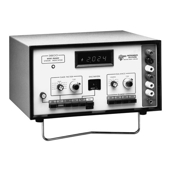
- Page 1 MODEL 3800 Wide Range Strain Indicator 3800 Instruction Manual Vishay Micro-Measurements P.O. BOX 27777, RALEIGH, NORTH CAROLINA 27611, USA TELEPHONE (919) 365-3800 FAX (919) 365-3945 www.vishaymeasurementsgroup.com measurementsgroup@vishay.com November 2002 130-000005...
-
Page 2: Table Of Contents
4.0 OPERATING PROCEDURES — Strain Gage Inputs ............... 5.0 OPERATING PROCEDURES — Transducers .................. 6.0 FUNCTIONAL DESCRIPTION ......................7.0 CALIBRATION & MAINTENANCE ....................10 WARRANTY ............................11 SCHEMATIC DIAGRAM........................12 © Copyright Vishay Micro-Measurements 1985, 2002 Printed in USA All Rights Reserved. - Page 3 Model 3800 Wide Range Strain Indicator...
-
Page 4: General Description
0.0500 to 50.00. Gage factor is automatically displayed when the function push button is in the SET position. Balance Method: Electronically injected counter-emf. The balance controls of the Model 3800 provide a total bal- Gage Factor: ance range of greater than ±100% of full-scale reading at a Range: 0.0500 to 50.00;... -
Page 5: Description Of Controls
S+ terminal, and the instrument is con- figured for full-bridge operation. This button is not inter- Power is applied to the Model 3800 by the toggle switch locked, and is selectable at the option of the user. -
Page 6: Operating Procedures Strain Gage Inputs
115 Vac or 230 Vac opera- zero. These settings are used to check for thermal offsets or tion. The FUSE for the Model 3800 is also mounted at the other extraneously injected voltages, or to check initial unbal- same location. -
Page 7: Quarter Bridge
NOTE: Leads marked "R" must be same length and size for best balance and stability. ACTIVE ACTIVE DUMMY GAGE OR RESISTOR INTERNAL DUMMY EXTERNAL DUMMY QUARTER BRIDGE ACTIVE ACTIVE TENSION TENSION ACTIVE ACTIVE COMPRESSION COMPRESSION GAGES ADJACENT GAGES APART HALF BRIDGE INPUT OUTPUT GAGES... - Page 8 BALANCE RANGE push button and repeat above steps. 15V range and the operating environment is relatively noise- free. The example below illustrates the use of the Model 3800 NOTE: If the GAGE FACTOR or EXCITATION will be for such applications.
-
Page 9: Operating Procedures Transducers
(120 or 350 ) rear-panel terminals. Section 4.9. Set EXCITATION to 10V. Depress the RUN push button. The Model 3800 will now indi- cate the measured strain in the test specimen. Resolution of Set the GAGE FACTOR range switch to the .18–.24 range. - Page 10 5.2 GAGE FACTOR Depress the AMP ZERO push button. Adjust the AMP ZERO The Model 3800 may be used to give a readout in engineering potentiometer for a reading of ±0000. units or in mV/V. Also, since a wide range of excitation is...
- Page 11 The bias current of the Model 3800 amplifier is on the order of 4 nA maximum at +25°C. 5.9 HIGH-RESOLUTION TRANSDUCER...
-
Page 12: Functional Description
Fig. 4 — Amplifier and amplifier control Figure 3 is a block diagram of the excitation control circuits of the Model 3800. U17 is a precision voltage reference, used for 6.3 BALANCE CONTROL AND INJECTION both the excitation circuits and as the reference voltage for the A/D converter. -
Page 13: Calibration & Maintenance
7.0 CALIBRATION & MAINTENANCE R106 Calibration of the Model 3800 to its specified levels of accu- FROM BALANCE TO BALANCE R109 INJECTION U6 INJECTION U7 racy is beyond the capability of most user organizations. R112 R115 Special test configurations and test equipment capable of ±0.01% accuracies are required. -
Page 14: Warranty
This warranty constitutes the full understanding between the manufacturer and buyer, and no terms, conditions, understanding, or agreement purporting to modify or vary the terms hereof shall be binding unless hereafter made in writing and signed by an authorized official of Vishay Mico-Measurements, Inc. -
Page 15: Schematic Diagram
These drawings and specifications are intended to provide information for the proper utilization or maintenance or calibration or repair of the items represented by qualified service personnel. They are, 3800 and shall remain the property of Vishay Micro-Measurements Group, and shall not be reproduced or copied, in whole or in part, as the basis for manufacture or sale of such item. 500-060349M...
Need help?
Do you have a question about the 3800 and is the answer not in the manual?
Questions and answers