Table of Contents

Subscribe to Our Youtube Channel
Related Manuals for Vishay P3


Summary of Contents for Vishay P3
- Page 1 Model P3 Strain Indicator And Recorder Instruction Manual Vishay Micro-Measurements P.O. Box 27777 Raleigh, NC 27611 USA Telephone: (919) 365-3800 Facsimile: (919) 365-3945 www.vishaymg.com micro-measurements@vishay.com March 2004 130-000109...
-
Page 2: Table Of Contents
& W ............7 EIGHT FRONT PANEL ............... 8 USB I ............8 NTERFACE ..........9 EMORY ............ 9 NPUT ONNECTORS LCD D ............10 ISPLAY ..............10 EYPAD © Copyright 2003-2004 Vishay Micro-Measurements Inc. Printed in USA All Rights Reserved... - Page 3 ..........10 OWER ONNECTOR ......... 10 NALOG UTPUT ONNECTOR OPERATION ..............11 ............ 11 ETTING TARTED ..............11 OWER ..........12 NPUT ONNECTIONS 4.3.1 Quarter Bridge Connections......12 4.3.2 Half Bridge Connections........13 4.3.3 Full Bridges and Transducers......13 ..........14 PERATIONAL ODES 4.4.1...
- Page 4 SOFTWARE OPERATION.......... 42 ..............42 VERVIEW ........... 44 ELECT HANNELS ........... 45 RIDGE ........46 ACTOR CALING ............. 47 OWER MENU .............. 48 ............49 ECORD ............52 ALANCE ............54 ALIBRATE 6.10 ............55 ACKLIGHT 6.11 ....56 OADING AVING ETUP NFORMATION...
- Page 5 Model P3 Strain Indicator and Recorder - 1 -...
-
Page 6: Description
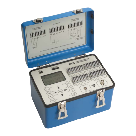
1 DESCRIPTION GENERAL The Model P3 Strain Indicator and Recorder is a portable, bat- tery powered precision instrument for use with resistive strain gages and strain-gage-based transducers. The Model P3 accepts full- half- and quarter-bridge inputs; all required bridge completion components for 120-, 350-, and 1000-ohm bridges are supplied. -
Page 7: Functional Features
FUNCTIONAL FEATURES The Model P3 Strain Indicator and Recorder incorpo- rates the following features: • Four input channels. • Direct-reading, backlit LCD display. • Data storage using the multimedia card. • Hardware and software support for quarter-, half- and full-bridge circuits. -
Page 8: Specifications
2 SPECIFICATIONS Note: Performance may be degraded at high levels of repetitive electrostatic discharge; however, no damage to the unit will occur. Input Connections Type: Tool-free eccentric lever release Quantity: Four Wire size: 16 to 28 AWG [1.29 to 0.31mm Φ] Bridge Configurations Types: Quarter-, half-, and full bridges Bridge Impedance: 60 to 2000 Ω... -
Page 9: Measurement Range/Resolution
Measurement Range/Resolution Strain Range: ±31,000 µε at GF = 2.000. (±15.5 mV/V) Resolution: ±1 µε at GF = 2.000 (±0.0005 mV/V) Measurement Accuracy ±0.1% of reading ±3 counts. (Analog output disabled, instrument Gage Factor = 2.000) Gage Factor Control Range: 0.500 to 9.900 Balance Control Type: Software Control: Manual or automatic... -
Page 10: Analog Output
Control: Software Values: P- to D120: 11.9KΩ ±0.1% (5000µε at GF = 2.00) P- to D350: 34.8KΩ ±0.1% (5000µε at GF = 2.00) P- to D1000: 99.5KΩ ±0.1% (5000µε at GF = 2.00) Remote calibration: Switch contacts at input terminal block 2.13 Analog Output Value: 0 to 2.5V max... -
Page 11: Size & Weight
2.17 Size & Weight Size: 9 x 6 x 6 in (228 x 152 x 152 mm) Weight: 4.4 lb (2.0 kg), including batteries - 7 -... -
Page 12: Front Panel
Power Analog Display Output Connector Connector USB Interface The USB interface is the communication channel between the P3 and a host PC. All front panel controls (except the system calibration option) are accessible via the USB interface. - 8 -... -
Page 13: Memory Card Slot
Input Connectors The input connectors connect the strain gage or transducer to the Model P3. To attach a wire to the input connector, simply lift the eccentric lever, insert the wire into the terminal opening, and lower the eccentric lever. -
Page 14: Lcd Display
LCD Display The LCD display provides the visual interface to control, setup, and monitor the P3. Keypad The keypad is a membrane-switch type. Functionality of the keys is described in the Operation section. Power Connector The power jack accepts a 6 to 15V DC source (0.1A max). -
Page 15: Operation
Adaptor, and (3) battery. If the Model P3 is using USB or the AC adaptor, the system will always remain on as long as power is supplied. If the Model P3 is using the USB or AC adapter as the power source, an "x" is displayed on the lower right corner of the LCD display, indicating the unit is running on external power. -
Page 16: Input Connections
Input Connections Strain gages and strain gage-based transducers are connected to the P3 through the input terminals. The P3 can accommodate up to four input channels, labeled 1 through 4. To connect the leadwire to the input terminal, lift the black arm of the desired terminal, insert the leadwire all the way into the terminal, and carefully lower the arm to clamp the wire to the terminal. -
Page 17: Half Bridge Connections
4.3.2 Half Bridge Connections The following figure illustrates the connections for making a three-wire half-bridge connection. S- D 4.3.3 Full Bridges and Transducers The following figure illustrates the connections for making a full-bridge connection: P+ S- P- S+ EXTERNAL CAL CIRCUIT - 13 -... -
Page 18: Operational Modes
In any case, the transducer manufacturer’s recommenda- tions should be followed. Operational Modes The Model P3 has two operational modes: the run mode and the command mode. 4.4.1 Run Mode Operation In the run mode, the display is divided into four quadrants (one for each channel), along with a status line on the bottom of the display. - Page 19 Note: While in the pause mode, recording to the MMC is also suspended. To resume to normal operation, press the key. 4.4.1.2 Peak Read In addition, the Model P3 can be used as a peak hold indicator. The peak hold function is accessed by using the arrow keys.
- Page 20 To reset the peak display, press the . To return to the normal (tracking) mode, press MENU Pressing the key will update the display if a value larger than the currently displayed value is measured. µε µε +01000 +00216 Min Peak ↓=Reset µε...
- Page 21 4.4.1.4 Auto Balance If any active channels are configured to use the auto balance mode, pressing the BAL key will initiate the auto balance sequence. The auto balance sequence requires confirmation to avoid unintentional rebalance of the signal. Ready to Auto Balance [BAL] = Balance [MENU] = Cancel...
-
Page 22: Command Mode Operation
4.4.1.6 Backlight While in the run mode, pressing the Backlight key will illuminate the backlight for the duration specified in the back- light options menu. 4.4.2 Command Mode Operation The command mode is entered when the user is in the run mode and the , key is pressed, or the MENU... -
Page 23: Select Channels Menu
** MAIN MENU ** Select Channels Bridge Type Gage Factor/Scaling Recording Balance Shunt Calibration Options The following table briefly describes the menu items and the section of this manual associated with the item. Menu Item Section Description 4.5.2 Displays the Select Channels Select Channels Menu. -
Page 24: Bridge Type Menu
In order to activate/deactivate a channel, use the keys to highlight the desired channel. Toggle the selection by using keys. Press the key to return to the run MENU mode. * SELECT CHANNELS * Chan 1: Active Chan 2: Active Chan 3: Active Chan 4: Active ←→... - Page 25 The table below summarizes the meaning of the provided bridge types. For more information on the calculations used by the Model P3, refer to the Interactive Guide for Strain Measure- ment Technology, available on the Vishay Micro-Measurements web site at http:// www.vishaymg.com.
- Page 26 Two active gages with equal strains of the same sign -- used on HB opp ε,- ε opposite sides of col- umn with low thermal gradient (bending can- cellation, for instance.) Two active gages with equal and opposite strains aligned with the maximum and mini- HB shear mum principal strains...
-
Page 27: Gage Factor/Scaling Menu
Four active gages in uniaxial stress field-- two aligned with maximum principal FB ν opp strain, the other two with transverse "Pois- son" strain (column). Default Poisson’s Ratio = 0.3. Four active gages in uniaxial stress field - two aligned with max- imum principal strain, FB ν... - Page 28 desired item, use the keys. Toggle the selection by using the keys. Press the key to return to the MENU run mode. Scaling options are determined by the units selected. To change the units, highlight the "Units" menu item and use the keys to scroll through the provided units.
- Page 29 *GAGE FACTOR/SCALING* Chan Units : mV/V 4.5.4.3 Other Engineering Units For convenience, the following other engineering units are pro- vided: Pounds per square inch Thousand pounds per square inch Gigapascals Megapascals Pascals Grams or G’s (acceleration) Pounds force Pounds Kilograms Inches Millimeters Mils (1/1000 of an inch)
- Page 30 Meters per second ^2 m/s2 Tons Degrees Fahrenheit °F Degrees Celsius °C Degrees Kelvin °K All of the above units assume linear scaling. In order to prop- erly scale the data, it is necessary to supply the full scale value (in the selected engineering units) and the mV/V output at the full scale value.
-
Page 31: Recording Menu
ommended to set this value at or near the expected full scale value when manually scaling the channel. To change the number of decimal places being displayed, high- light the "Dec. places" menu item and use the keys to change the value. The range of decimal places is 0-3. 4.5.5 Recording Menu The recording menu selects the recording mode and the rate at which data is recorded to the multimedia card (MMC). -
Page 32: Balance Mode Menu
4.5.5.2 Manual Recording In the Manual recording mode, selected channels are recorded whenever the key is pressed. * RECORDING * Mode : Manual Chan 1 : ON Chan 2 : OFF Chan 3 : OFF Chan 4 : OFF ←→ Toggle Menu=Exit 4.5.5.3 Auto Recording In the Auto recording mode, selected channels are recorded at... - Page 33 Channels using the auto balance mode will automatically be balanced when the key is pressed while in the run mode. The P3 makes a series of measurements and uses the mean value as the balance value. * BALANCE MODE *...
-
Page 34: Shunt Calibration Menu
* BALANCE MODE * Chan: 1 Mode: Manual Adjust ←→ +00010 ←→ Toggle Menu=Exit 4.5.6.3 Disable Balance This mode disables the balance function. Channels using this mode have no correction for balance; however the initial ampli- fier zero is removed. This mode allows the user to evaluate ini- tial bridge offsets. -
Page 35: Options Menu
selected, the keys can be used to increase/decrease the sensitivity. SHUNT CALIBRATION Chan: 1 Adjust ←→ +05000 4.5.8 Options Menu The Options Menu provides the ability to modify settings not directly related to making measurements. Use the arrow keys to highlight the desired menu item. Choose the de- sired item by pressing the key. -
Page 36: Display Options Menu
4.5.13 Advanced options Advanced 4.5.18 Displays the firmware version of Version the Model P3 Returns to the Run Mode Exit 4.5.9 Display Options Menu The Display Options menu allows the user to modify the LCD display parameters. Use the keys to select the desired item. -
Page 37: Output Options Menu
Note: If the backlight is illuminated while the key is MENU pressed, the backlight will remain illuminated until the P3 re- turns to the run mode. 4.5.9.2 Contrast The contrast control adjusts the contrast of the LCD display. Temperature variations may make it necessary to adjust the con- trast of the LCD for the best viewing experience. -
Page 38: Save Setup Option
A/D converter and excitation is constantly on. Only one channel can be active at a time. 4.5.10.3 Rejection The digital filters in the Model P3 can be tuned to optimize the noise rejection from power line frequencies. Choose between 50Hz and 60Hz 4.5.10.4 Out Range... -
Page 39: Advanced Options Menu
Poisson Ratio: 0.30 Factory Defaults Exit 4.5.14 Calibrate System This option allows the user to recalibrate the Model P3. This process requires a Vishay Micro-Measurements Model 1550A Strain Indicator Calibrator, or another device with equivalent features and specifications. * ADVANCED OPTIONS *... - Page 40 System calibration is accomplished by making four measure- ments on each channel (amp zero, zero, positive and negative full scale). Once the measurements are made and the data vali- dated, calibration values for amplifier zero and software gain are stored in the internal flash memory. Readings are validated by comparing the measured values with tolerances which are hard coded within the firmware.
- Page 41 Connect the Model P3 to a Model 1550A Strain Indicator Cali- brator, configured as a full bridge circuit, to channel 1. Set the 1550A to read 0 microstrain, positive polarity, and press the key. The system will make a series of measurements, and evaluate the average readings.
- Page 42 The system will make another series of measurements, validate the readings, and, if valid, will display the next step: SYSTEM CALIBRATION Set calibrator to -30000 microstrain CAL = Calibrate Set the 1550A calibrator to -30000 (negative polarity), and press the key.
-
Page 43: Erase Mmc
NOTE: The model P3 is a ratiometric measuring device, so the measurement is not affected by fluctuations in the excitation voltage. It is therefore important to use a Wheatstone Bridge- based calibrator. -
Page 44: Poisson's Ratio
Use the keys to increase or decrease this value. The factory default is 0.3. 4.5.17 Factory Defaults This option returns the P3 to its initial factory settings. The set- tings can be made permanent by pressing the record key when prompted. -
Page 45: Battery Replacement
5 Battery Replacement When the P3 is operated under battery power, battery condition is indicated by the battery icon, located on the lower right hand corner of the screen in the run mode. µε µε +01000 +00216 µε µε +00524 +00914 When the battery icon indicates that the battery is low (by re- placing the battery icon with "LO"... -
Page 46: Software Operation
Model P3. To operate the software, connect the USB interface on the model P3 to an open USB port on the PC using the supplied ca- ble. Once physically connected, start the application from Win- dows by navigating to the following menus: Start->Programs->Vishay Micro-Measurements->Model... - Page 47 To access this document, right click anywhere on the P3 image and select "Help", or press the F1 key. To minimize the dis- play, right click and select "Minimize". Various functions are accessible by moving the mouse over the desired button and left clicking. Specific functions are described in the following sections.
-
Page 48: Select Channels
Select Channels The Select Channels button chooses which channels will be displayed and (optionally) recorded. Select the desired channels by clicking on the appropriate channel button. If the button is illuminated, the channel is selected. Press OK to complete the selection, or Cancel to abort the op- eration. -
Page 49: Bridge Type
Bridge Type The Bridge Type Button chooses the type of bridge configura- tion and scaling is to be used. Choose the bridge type from the drop-down list of configurations. Possible configurations are described in section 4.5.3. Press the OK button to change the settings. -
Page 50: K Gage Factor /Scaling
Gage Factor/Scaling The Gage Factor/Scaling dialog provides a means to select the scaling and labels shown on the P3 and the screen. Choose the appropriate engineering units. The dialog dynami- cally changes the settable properties depending on the engineer- ing units selected. -
Page 51: Power
Power Clicking on the Power button closes the Model P3 Application. - 47 -... -
Page 52: Menu
Menu Clicking on the Menu Button displays the main menu on the PC, just as pressing the Menu button on the P3. To choose a menu item, simply move the mouse pointer over the item. When the item is highlighted, click the left mouse button. The list of menu items is the same as described in section 4.5, except for... -
Page 53: Record
Record Clicking on the Record button chooses the desired recording options. Highlight the desired recording options, and click OK to begin recording. - 49 -... - Page 54 If recording to the PC, a window will appear displaying the val- ues in numeric or graphical format. To stop recording, press the "Stop" button. To save the data to a file, press "Save". The data can be saved in the following for- mats: Rich text, ASCII, Excel, HTML, or XML.
- Page 55 If recording to the Multimedia card, the following dialog is dis- played. Press the "Rec" button to begin recording. Press the "Stop" but- ton to stop recording. - 51 -...
-
Page 56: Balance
Balance The balance button provides the ability to change the balance mode of each channel and to adjust the balance manually or automatically. Choose the desired balance mode for each channel. If a channel is not selected, it will not be shown. To auto balance one or more channels, select the Auto balance option, and press the Zero button. - Page 57 To Manually balance, select "manual", and adjust the slider to obtain the value near the desired reading. To make finer adjust- ments, press the up and down arrow buttons located above and below the corresponding slider control. The arrow buttons can be used in conjunction with the [Shift], [Alt], and [Ctrl] keys.
-
Page 58: Calibrate
Calibrate Channel sensitivity can be set by clicking the calibrate button. To enable shunt calibration, press the CAL button. Use the slider control to make coarse adjustments to the sensitivity. Finer adjustments can be made by holding down the up and down arrows. -
Page 59: Backlight
6.10 Backlight The backlight button illuminates the simulated backlight on the PC screen and activates the backlight on the P3. - 55 -... -
Page 60: Loading/Saving Setup Information
6.11 Loading/Saving Setup Information System setup information, including balance and scaling infor- mation can be saved to the flash memory on the P3 or loaded and/or saved to the PC by choosing Load/Save setup from the Options menu. When selected, the following dialog appears: Choose the desired option and press OK. -
Page 61: Transferring Data
6.12 Transferring Data Data stored on the Multimedia card may be downloaded via the USB interface by clicking on the Multimedia Card region on the screen or by selecting "Download Data" from the Options menu. To list the files on the MMC, press the "List" button. To Download a file, select the desired file and press the "Get"... - Page 62 - 58 -...
-
Page 63: Upgrading Firmware
6.13 Upgrading Firmware To upgrade to a newer version of firmware, select "Upgrade Firmware" from the Advanced Options menu. When selected, the following dialog appears: Press "Open" to select the firmware to use. The version of the firmware will be displayed on the dialog. Press the Start button to begin the upgrade. - Page 64 firmware version. If successful, the new version of the firmware will execute the next time the system is powered up. - 60 -...
- Page 65 Vishay Micro-Measurements reserves the right to make any changes in the design or construction of its instruments at any time, without incurring any obligation to make any change whatever in units previously delivered. Vishay Micro-Measurement’s sole liabilities, and buyer’s sole remedies, under this agreement shall be limited to the purchase price, or at our sole discretion, to the...
Need help?
Do you have a question about the P3 and is the answer not in the manual?
Questions and answers