Table of Contents
Advertisement
Quick Links
Advertisement
Table of Contents

Related Manuals for Barco XDX-4K25


Summary of Contents for Barco XDX-4K25
- Page 1 User guide ENABLING BRIGHT OUTCOMES...
-
Page 2: Product Revision
Product revision Software Revision: 1.7.0 Barco NV Beneluxpark 21, 8500 Kortrijk, Belgium www.barco.com/en/support www.barco.com... - Page 3 Barco. If the purchaser or a third party carries out modifications or repairs on goods delivered by Barco, or if the goods are handled incorrectly, in particular if the systems are operated incorrectly or if, after the transfer of risks, the goods are subject to influences not agreed upon in the contract, all guarantee claims of the purchaser will be rendered invalid.
-
Page 4: Software License Agreement
This software and the accompanying files are sold “as is” and without warranties as to performance or merchantability or any other warranties whether expressed or implied. In no event shall Barco be liable for damage of any kind, loss of data, loss of profits, business interruption or other pecuniary loss arising directly or indirectly. -
Page 5: Table Of Contents
Table of contents 1 Safety ..........................................13 General considerations ................................14 Important safety instructions..............................15 Product safety labels..................................19 High Brightness precautions: Hazard Distance ......................20 HD for fully enclosed projection systems...........................22 HD in function of modifying optics ............................24 Compliance ......................................24 2 Getting started......................................25 Explaining the power states ..............................26 Switching the projector ON................................28 Connecting to the projector for the first time........................29 Switching the projector OFF ..............................30... - Page 6 4.10 User rights......................................61 4.11 Displaying open source license list............................62 4.12 Application Menu tree...................................63 5 Projector configuration process overview........................65 Prerequisites......................................66 Process overview....................................66 6 Control - Projector....................................69 Macros control ....................................70 6.1.1 About macro control ..............................70 6.1.2 Activating a macro using the control menu....................70 Light, dowser, lens..................................71 6.2.1 About Light, dowser, lens menu..........................71...
- Page 7 7.1.14 Deleting a macro ..............................104 7.1.15 Deleting several macro files..........................105 PCF........................................105 7.2.1 About PCF..................................105 7.2.2 Creating a PCF with active configuration ....................106 7.2.3 Activating a PCF............................... 107 7.2.4 Renaming a PCF..............................108 7.2.5 Importing a PCF................................ 109 7.2.6 Exporting a PCF ................................110 7.2.7...
- Page 8 7.6.7 Importing an input file ............................153 7.6.8 Exporting an input file ............................154 7.6.9 Exporting several input files in a backup package ................155 7.6.10 Delete an input file..............................157 7.6.11 Deleting several input files..........................157 Picture ........................................ 158 7.7.1 About screen file...............................
- Page 9 9.3.2 Creating a new MCGD file ..........................206 9.3.3 Editing an active MCGD file ..........................206 9.3.4 Exporting and importing MCGD files......................207 9.3.5 Deleting several MCGD files ..........................208 Verifying the colors after correction ........................... 209 Spatial color calibration ................................212 9.5.1 About spatial color calibration...........................
- Page 10 13.2 Notifications..................................... 267 13.3 Metrics........................................ 269 14 Diagnostics - Analysis................................... 273 14.1 Self test......................................274 14.2 Diagnostic package ..................................275 14.3 Reading a diagnostic package ............................. 276 15 Maintenance......................................279 15.1 Software update.................................... 280 15.2 Service mode ....................................283 15.3 Download and restore full system backup ........................
- Page 11 Index ..........................................327 R5914478 /03...
- Page 12 R5914478 /03...
-
Page 13: Safety
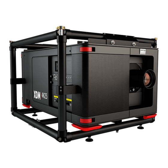
Barco product: • XDM-4K25 Barco provides a guarantee relating to perfect manufacturing as part of the legally stipulated terms of guarantee. Observing the specification mentioned in this chapter is critical for projector performance. Neglecting this can result in loss of warranty. -
Page 14: General Considerations
• Before operating this equipment please read this manual thoroughly and retain it for future reference. • Installation and preliminary adjustments should be performed by qualified Barco personnel or by authorized Barco service dealers. • All warnings on the projector and in the documentation manuals should be adhered to. -
Page 15: Important Safety Instructions
Safety to minimize the potential risk to themselves or other persons. The term USER and OPERATOR refers to any person other than SERVICE PERSONNEL or TRAINED PROJECTIONISTS, AUTHORIZED to operate professional projection systems. The TRAINED PROJECTIONISTS may only perform the maintenance task described in the User & Installation manual. -
Page 16: To Prevent Personal Injury
Do not place flammable or combustible materials near the projector! • Barco large screen projection products are designed and manufactured to meet the most stringent safety regulations. This projector radiates heat on its external surfaces and from ventilation ducts during normal operation, which is both normal and safe. -
Page 17: To Prevent Battery Explosion
In the event of fire, use sand, CO or dry powder fire extinguishers. Never use water on an electrical fire. Always have service performed on this projector by authorized Barco service personnel. Always insist on genuine Barco replacement parts. Never use non-Barco replacement parts as they may degrade the safety of this projector. - Page 18 Replacement parts: When replacement parts are required, be sure the service technician has used original Barco replacement parts or authorized replacement parts which have the same characteristics as the Barco original part. Unauthorized substitutions may result in degraded performance and reliability, fire, electric shock or other hazards.
-
Page 19: Product Safety Labels
Safety 1.3 Product safety labels Light beam related safety labels Label image Label description Label location DANGER! CLASS 4 LASER RADIATION WHEN OPEN. AVOID EYE OR SKIN EXPOSURE TO DIRECT OR SCATTERED RADIATION. DANGER! RAYONNEMENT LASER DE CLASSE 4 EN CAS D’OUVERTURE. EXPOSITION DANGEREUSE AU RAYONNEMENT DIRECT OU DIFFUS DES YEUX OU DE LA PEAU. -
Page 20: High Brightness Precautions: Hazard Distance
Safety Electric related safety labels Label image Label description Label location Disconnect the power to the unit mains terminals and unplug power cord at UPS inlet before removing this cover. See ID-label for ratings. WARNING : HIGH LEAKAGE CURRENT EARTH CONNECTION ESSENTIAL BEFORE CONNECTING SUPPLY. - Page 21 Safety Restriction Zone (RZ) based on the HD The HD depends on the amount of lumens produced by the projector and the type of lens installed. See chapter “HD in function of modifying optics”, page To protect untrained end users (as cinema visitors, spectators) the installation shall comply with the following installation requirements: Operators shall control access to the beam within the hazard distance or install the product at a height that will prevent spectators' eyes from being in the hazard distance.
-
Page 22: Hd For Fully Enclosed Projection Systems
The LIP shall be installed by Barco or by a trained and Barco-authorized installer or shall only be transferred to laser light show variance holders. This is applicable for dealers and distributors since they may need to install the LIP (demo install) and/or they transfer (sell, rent, lease) the LIP. - Page 23 Safety Restriction Zone (RZ) based on the HD The projector is also suitable for rear projection applications; projecting a beam onto a defuse coated projection screen. As displayed in Image 1– 3 two areas should be considered: the restricted enclosed projection area (RA) and the observation area (TH).
-
Page 24: Hd In Function Of Modifying Optics
Throw Ra o (TR) Image 1–4 Hazard Distance Throw Ratio 1.7 Compliance UK Compliance This product is fit for use in the UK. Authorised Representative: Barco UK Ltd Address: Building 329, Doncastle Road Bracknell RG12 8PE, Berkshire, United Kingdom R5914478 /03... -
Page 25: Getting Started
Getting started Explaining the power states......................26 Switching the projector ON ......................28 Connecting to the projector for the first time ..................29 Switching the projector OFF ......................30 Operation in 24/7 Mode.........................31 Web Communicator ........................32 Web Commander .........................32 Physical installation Instructions for the physical installation of this projector are not included in this document (User Guide) . For physical installation instructions (e.g. -
Page 26: Explaining The Power States
Getting started 2.1 Explaining the power states Power states explained The projector can have one of several power states, which you can recognize by the state of the power LED. Projector Behavior Power LED Power State Mains power off Projector is not powered OFF mode The power button and GPI3 are powered (for remote power-on). -
Page 27: Force Shutdown
Getting started Image 2–2 Location of the Power button and GPI 1-4 input on the Cinema Controller. Power state diagram FORCE SHUTDOWN START-UP >6sec SHUTDOWN 1 sec READY READY Image on the screen Image 2–3 Power State diagram R5914478 /03... -
Page 28: Switching The Projector On
Getting started 2.2 Switching the projector ON Possible ways to switch on There are multiple ways to switch on the projector, depending on a few factors: Current How to power on Notes Power Stage After the projector is powered, you can •... -
Page 29: Connecting To The Projector For The First Time
Getting started Ensure the projector is correctly connected to the mains power. Ensure that the correct lens is installed for your application. Browse to the IP address of the projector, using the http protocol. With the projector in ECO mode, you will be redirected to the ECO mode page. Image 2–5 Example of the Eco Mode page in Web Communicator On the Eco mode page, press Wake up. -
Page 30: How To Connect
Getting started Setting Item Default gateway 192.168.100.1 Default hostname [projector model] - [serial number] How to connect? 1. On the touch display of the projector, press either About, or Settings to see the IP address assigned to the projector. 2. Use a web browser to browse to the assigned IP address. The login page of Web Communicator will be displayed. -
Page 31: Operation In 24/7 Mode
Getting started Image 2–7 Example of the ECO menu on the touch display How to put the projector in ECO mode, using the Web Communicator? In the Communicator, browse to Control >> Power. In the Power menu, press Switch to ECO mode and confirm. Image 2–8 How to turn the projector OFF? Press the power button for more than six seconds. -
Page 32: Web Communicator
The Web Communicator application is a uniquely powerful and easy to use built-in web application for the Barco projector. This application provides all the necessary tools necessary to setup and control the connected projector. A comprehensive array of easy to access menu pages provide the projectors digital input, output and screen display via a combination of simple buttons and displays. - Page 33 Getting started Image 2–10 The Web Commander has its own user guide, of which you can find the latest version on the Barco website. R5914478 /03...
- Page 34 Getting started R5914478 /03...
-
Page 35: Touch Display
The touch display is an optional accessory which, when present, is located in the upper part of the card cage (above the Barco Cinema controller). The touch display is an easy way to access basic functionality like setting the network address, switch to Eco mode or execute direct commands (e.g. -
Page 36: General
Touch display 3.1 General Overview When present, the touch display is located in the upper part of the card cage, above the Barco Cinema controller (reference 1, Image 3–1). Image 3–1 Touch display in card box The panels displayed in the touch display are organized around a top bar (on the top), a status bar (on the bottom) and a working area (center of the screen). -
Page 37: Status Bar
Touch display Top bar Top bar is always present regardless of the displayed panel. The name of the current panel is displayed on the left of the top bar (reference 2, Image 3–3). The auditorium name (reference 3, Image 3–3),provided during installation via the Web Communicator application, is displayed on the right of the top bar. - Page 38 Touch display Image 3–5 “Projector control” panel Light Source on-off Lens shift Light Source power increase-decrease Test pattern status Dowser open-close Dowser status Test pattern on-off Projector light source status Lens zoom Locked button Lens focus How to switch on or switch off the projector light source On the touch display, while in Main >...
-
Page 39: Notifications Panel
Touch display This dowser on the projector is not a mechanical dowser, but a software functionality. How to activate or deactivate selected test pattern On the touch display, while in Main > Projector control, Click Test pattern button (reference 4, Image 3–5) to activate test pattern. -
Page 40: Presets Panel
Touch display Image 3–6 “Notifications” panel Error list Warning list Caution/Info list 3.4 Presets panel Overview This panel allows to execute a macro associated to a preset button. The association of a macro with a touch display button is done in Web communicator (Panel: Configuration > Projector > Macros). When a button is not linked to a macro (reference 2, Image 3–7), it label is No macro linked and it is no longer... -
Page 41: Eco (Power) Panel
Touch display 3.5 Eco (power) panel Overview This panel groups together two commands related to power modes: • Switch to Eco mode (reference 1, Image 3–8). This will power down the media server and put in standby mode the projector electronic. •... -
Page 42: User Interface
Touch display Image 3–9 “Settings” panel Settings mode (automatic/Manual) Apply button Ip (Internet Protocol) - default IP address : 192.168.100.2 Connection status Default Gateway Switch to choose the theme (Light/Dark) Subnet mask Panel in Dark theme DNS server User interface A switch (reference 8, Image 3–... -
Page 43: About Panel
Touch display Other network parameters (reference 2, 3, 4 and 5, Image 3–9) can no longer be manually edited. You should not have to configure anything. Click Apply (reference 6, Image 3–9). The configuration provided by the DHCP server becomes active. How to set up manually the network configuration On the touch display, while in Main >... -
Page 44: Product Information
Touch display Image 3–10 “About” panel Product information Network information Product information • Model : Indicates the Model of the projector (e.g. DP4K-xx). • Article number: Indicates article number of the projector (e.g. R90xxxxx). • Serial number: Indicates the serial number of the projector. •... -
Page 45: Web Communicator - Graphical User Interface (Gui)
Web Communicator – Graphical User Interface (GUI) Graphical User Interface .......................46 Starting up ...........................49 Installing SSL certificate to enable HTTPS protocol .................50 Reset administrator password .......................55 Signing out from application ......................56 Modifying account settings (password) ...................57 Modifying preferences (language, theme, time format) ..............58 Search............................59 Dashboard ...........................60 4.10 User rights ...........................61... -
Page 46: Graphical User Interface
Menu bar In the Web Communicator application, the Menu bar is always present regardless of the displayed page. Auditorium name, date and time (reference 1) are displayed next to Barco logo. For more details concerning Auditorium name, please refer to chapter “Network configuration”, page... -
Page 47: Side Bar
Web Communicator – Graphical User Interface (GUI) Image 4–2 Auditorium name Dashboard shortcut General menu User icon WebCommander shortcut (optional) Status bar In the Web Communicator application, the Status bar is always present regardless of the displayed page. Status icons (reference 1) provide information on the respective status of the dowser, the light source and the test pattern. - Page 48 Web Communicator – Graphical User Interface (GUI) Image 4–4 Active menu Name of the sub section where the menu is located Special GUI behavior on a limited screen area When Web communicator is used in small window or when it runs on a device with a restricted display (e.g. a smart phone), a space-saving mechanism is automatically activated.
-
Page 49: Starting Up
Web Communicator – Graphical User Interface (GUI) Click on an element (reference 3) of the menu allows to display a sub menu. Continue to navigate in this way in the sub-levels to reach the targeted page. Click on the cross (reference 4) to close the menu. Available list actions Many pages of the application are based on a list of elements (reference 1) with slider (reference 2). -
Page 50: Installing Ssl Certificate To Enable Https Protocol
For more details, please see the chapter dedicated to user rights in the next sections. Image 4–9 The landing page can be accessed at any time by clicking on the Barco logo located on the Menu bar. 4.3 Installing SSL certificate to enable HTTPS... - Page 51 Web Communicator – Graphical User Interface (GUI) (Secure Sockets Layer) certificate. The SSL certificate need to be downloaded from the projector web site and manually installed on the web browser. Once the SSL certificate is installed the HTTPS protocol is enabled and the future connections will be established automatically as long as the certificate is valid.
- Page 52 Web Communicator – Graphical User Interface (GUI) Image 4–11 Click on the site information button (reference 2) on the left of the url to display the menu. Click on View Certificate (reference 3) to open up the certificate popup. Click on the Details tab (reference 4). Click to Copy to File (reference 5) to open up the Certificate Export Wizard.
- Page 53 Web Communicator – Graphical User Interface (GUI) Image 4–13 Click to Next (reference 10), then click Finish (reference 11). The SSL file (certificate) is now available and need to be installed on your Browser. How to install the SSL certificate in your browser Open a chrome browser and click Customize and control button (reference 1) in the upper right corner.
- Page 54 Web Communicator – Graphical User Interface (GUI) Image 4–15 Click on the Trusted Root Certification Authorities tab (reference 7). Click to Import (reference 8) to open up the Certificate Import Wizard, then click Next (reference 9). Specify the location and the name where the certificate is saved (reference 10) or use Browse... to retrieve the certificate (reference 11), then click Next (reference 12).
-
Page 55: Reset Administrator Password
Web Communicator – Graphical User Interface (GUI) Image 4–16 Click Next (reference 13), then click Finish (reference 14) to close the Certificate Import Wizard. After few seconds a Security Warning popup will appear. Click Yes (reference 15). And finally click Ok in the Certificate Import Wizard. SSL certificate is successfully imported. -
Page 56: Signing Out From Application
Web Communicator – Graphical User Interface (GUI) Image 4–17 Click on generate challenge button (reference 1). A challenge key number is generated (reference 2). Click to copy icon (reference 3) to copy the challenge key number in the clipboard. Tip: Saving this number in the clipboard will allow you to reuse it easily in the following steps. Send a password reset request to the help desk. -
Page 57: Modifying Account Settings (Password)
Web Communicator – Graphical User Interface (GUI) Image 4–18 Select Logout (reference 2). User is disconnected and login page is displayed. Credentials and password will be required to use the application again. 4.6 Modifying account settings (password) About account settings Entire management of user (add or remove a user, change settings) is done in Configuration >... -
Page 58: Modifying Preferences (Language, Theme, Time Format)
Web Communicator – Graphical User Interface (GUI) 4.7 Modifying preferences (language, theme, time format) How to select another language Click on user icon (reference 1). Menu is displayed. Image 4–20 Click Preferences (reference 2). The Preferences window is prompted. Select a language in the Select language drop down list (reference 3). Click on Apply to change language. -
Page 59: Search
Web Communicator – Graphical User Interface (GUI) How to change time format Click on user icon (reference 1, Image 4–20). Menu is displayed. Click Preferences (reference 2, Image 4–20). The Preferences window is prompted. Select the time format in the Select time format check list (reference 5, Image 4–20). -
Page 60: Dashboard
Web Communicator – Graphical User Interface (GUI) Image 4–22 Click on the reset icon to reset the search. Image 4–23 The entire list is displayed again. Nothing is filtered. 4.9 Dashboard About dashboard At any time you can display dashboard to obtain status of Series 4 projectors connected on local network. For each projector displayed on dashboard you have: •... -
Page 61: User Rights
Web Communicator – Graphical User Interface (GUI) Image 4–25 Dashboard (reference 2) is displayed. To quit dashboard, click the x (reference 3) button in the top right corner. Dashboard is closed. 4.10 User rights About users Access to Web Communicator application is regulated by a principle of recognition of the user via a login. The user must be connected in order to perform an action (Control projector, modify settings,…). -
Page 62: Displaying Open Source License List
Web Communicator – Graphical User Interface (GUI) User groups and limitations All users belong to one of the following user groups: Groups Description Administrator • Unlimited access to all application panels (projector control and settings, media server settings and automations). •... -
Page 63: Application Menu Tree
Web Communicator – Graphical User Interface (GUI) Image 4–26 Click Open source license (reference 2). List of software components used in this application and currently under an open source license is displayed. Use the vertical scroll bar to scroll the list. Click on Close. - Page 64 Web Communicator – Graphical User Interface (GUI) Control Con guration Diagnostics Maintenance Projector Projector Projector Monitoring Software update Macro Macro System information Service mode Light, dowser, lens Noti cations Backup and restore Test Patterns Lens selection Metrics Laser Management Power Lens Position Analysis Analysis...
-
Page 65: Projector Configuration Process Overview
Projector configuration process overview Prerequisites ..........................66 Process overview .........................66 About this chapter After you have physically installed the projector, you can start with the configuration process of your XDM projector. This chapter gives an overview of all the different stages in the configuration process which you have to follow to get your XDM projector up and running. -
Page 66: Prerequisites
Projector configuration process overview 5.1 Prerequisites Overview Prerequisites may vary depending on the projector model to install. The list of prerequisites provided here is indicative. For more information on each prerequisite, please consult the installation manual of the projector. List of prerequisites The following prerequisites must be met before you start configuring the projector: •... - Page 67 Projector configuration process overview process for every projection format, lens and projector position you want to use this projector for. See procedure “Creating a lens position file”, page 119. Tip: It is recommended to create a slightly larger picture (2 or 3 pixels) to facilitate masking step that will come later.
- Page 68 Projector configuration process overview R5914478 /03...
-
Page 69: Control - Projector
Control - Projector Macros control..........................70 Light, dowser, lens ........................71 Test patterns control ........................76 Power ............................80 Scheduler ............................82 About this menu Control > Projector menu groups together all actions used to directly interact with the projector. It will be used to execute projector commands (e.g. zoom, open dowser, switch on the light source, ...), select and display patterns, or activate pre-programmed macros. -
Page 70: Macros Control
Control - Projector 6.1 Macros control 6.1.1 About macro control Location & access Menu: Control > Projector > Macros Level: Administrator, Service technician, Show manager Overview All macros available in the projector are listed here. Use this page to activate a macro. Use sort tool , at top of the list, to sorted macros by ascending or descending alphabetical order, ascending or descending preset number or creation date. -
Page 71: When An Error Occurs
Control - Projector Image 6–2 Status of the macro (reference 2) turns to BUSY and content of the macro is executed (e.g. close dowser, activate PCF file ...). After few moments execution is done. Status of the macro (reference 3) turns to EXECUTED. Image 6–3 When an error occurs If for some reason the macro does not run correctly, the status turns to COMMANDFAILURE. -
Page 72: Light Source On-Off
Control - Projector Image 6–5 Control > Projector > Light, Dowser, Lens Light Source on-off Lens focus Light Source power increase-decrease Lens shift Dowser open-close Projector light source status Test pattern on-off Dowser status Lens zoom Test pattern status 6.2.2 Light Source on-off Location &... -
Page 73: Dowser Open-Close
Control - Projector Use the minus button to decrease the light source power. Intensity of the light source changes. Image 6–6 The minimum light source power is limited to 20%. 6.2.4 Dowser open-close Location & access Menu: Control > Projector > Light, dowser, lens Level: Administrator, Service technician, Show manager This dowser on the projector is not a mechanical dowser, but a software functionality. -
Page 74: Lens Zoom
Control - Projector 6.2.6 Lens zoom Location & access Menu: Control > Projector > Light, dowser, lens Level: Administrator, Service technician, Show manager How to zoom in or zoom out Use the plus button to zoom in. Use the minus button to zoom out. Image 6–7 Use keyboard arrows as described in “Control key shortcut”, page... -
Page 75: Control Key Shortcut
Control - Projector Image 6–9 Use keyboard arrows as described in “Control key shortcut”, page 6.2.9 Control key shortcut Overview To facilitate lens settings, there are keyboard shortcuts that allow you to zoom, focus or position the lens while keeping your attention on the screen. Description [TAB] Tabulation key allows to toggle between Zoom, Focus and Shift settings. -
Page 76: Test Patterns Control
Control - Projector Image 6–10 One of the three available settings (Zoom, Focus or Shift) is selected. Selected control is highlighted with a blue rectangle. Use [TAB] key (reference 1) to toggle between Zoom, Focus and Shift settings. Each time [TAB] is pressed, the selected control change (reference 5). The blue rectangle that highlight the area moves to the next one. -
Page 77: Activating A Test Pattern Using The Control Menu
Control - Projector Image 6–11 Each test pattern displayed in this menu has a Name (reference 1). When a test pattern is activated the following are available: • the status of the test pattern (reference 3) turns to Active. • name of the test pattern is noticed on top of the list (reference 2). -
Page 78: Deactivating A Test Pattern Using The Control Menu
Control - Projector Image 6–12 Click Activate (reference 2). The test pattern is now selected and automatically activated: • Name of the test pattern is now displayed at the top of the list (reference 3). • Status of the test pattern (reference 4) turns to Active. •... - Page 79 Control - Projector Click on the Off TestPattern icon located on the top right of the list to deactivate the current test pattern without retrieve it in the list. Image 6–14 How to deactivate a test pattern While in Control > Projector > Test patterns, locate the currently activated test pattern. The status of the active test pattern is Activate (reference 2) and its name is noticed on top of the list (reference 1).
-
Page 80: Power
Control - Projector Image 6–16 6.4 Power 6.4.1 About Power menu Location & access Menu: Control > Projector > Power Level: Administrator, Service technician, Show manager Overview This page groups together three commands related to power modes: • Switch to ECO mode (reference 1). This will power down the media server and put in standby mode the projector electronic. -
Page 81: Switching To Eco Mode
Control - Projector Image 6–17 About Power modes For more information concerning the power states of the projector, please refer to “Explaining the power states”, page 6.4.2 Switching to ECO mode Location & access Menu: Control > Projector > Power Level: Administrator, Service technician, Show manager How to switch While in Control >... -
Page 82: Full System Reboot
Control - Projector Confirmation window is displayed to inform the user of consequences to switch to ECO mode. By example, this message inform if other users are currently connected or if playback is in progress. Click on the OK to confirm and continue. The projector switches to ECO mode. - Page 83 Control - Projector Image 6–21 The scheduler allows an overview on one entire week. The date of the week is displayed on the top (reference One column represents a day of the week. Slots in the day are represented by rectangles (one slot each half hour).
-
Page 84: Scheduling Of Automatic Switches On Or Shutdowns Of The Projector
Control - Projector Image 6–22 6.5.2 Scheduling of automatic switches on or shutdowns of the projector.. How to add an automatic switch on or an automatic shutdown of the projector in the scheduler While in Control > Projector > Scheduler, locate and click the empty slot where you want add an action in the scheduler. - Page 85 Control - Projector Check one or several days of the week in the “recurrent days ”section (reference 4) to repeat this action in the week (recurrence). Click Save (reference 5). The action is added in the scheduler (reference 7) and the areas located between the Go to ECO and the Wake-up is in green hatched (reference 8).
- Page 86 Control - Projector R5914478 /03...
-
Page 87: Configuration - Projector
Configuration - Projector Macros configuration ........................88 PCF............................105 Lens selection ..........................114 Lens position..........................118 3D ............................. 127 Input ............................144 Picture ............................158 Test patterns ..........................175 Internal clock settings ......................... 184 7.10 Image Orientation ........................187 About this menu The Configuration >... -
Page 88: Macros Configuration
Configuration - Projector 7.1 Macros configuration 7.1.1 About macro configuration Location & access Menu: Configuration > Projector > Macros Level: Administrator, Service technician Overview This panel allows to manage macros of the projector. Use sort tool , at top of the list, to sorted macros by ascending or descending alphabetical order, ascending or descending preset number or creation date. -
Page 89: Creating A New Macro
Configuration - Projector • New from active state (reference 14) allows to create a new macro pre-filled with commands corresponding to current projector state. • Import (reference 15) allows to import macro. • Export (reference 16) creates a downloadable backup package that contains all macro files selected in the list. -
Page 90: Creating A New Macro From Active State
Configuration - Projector 7.1.3 Creating a new macro from active state How to create a new macro from current projector state Check if projector settings are in accordance to the desired configuration. While in Configuration > Projector > Macros, click on the menu icon located on the top right of the list to select New macro from active state. -
Page 91: About Commands
Configuration - Projector A macro can contain at least: • an input file • a screen file • a PCF file • a 3D file • a 2D MCGD file • a light sensor calibration file • a lens position file A macro can be executed in one of the following: •... - Page 92 Configuration - Projector Image 7–5 Click Move (reference 3) located to the right of the command. The command is automatically added at the end of the list (reference 4) with the correct sequence number (reference 5). Parameter status (reference 6) is Unassigned as attributes of the command are not settled. drag and drop the command (reference 7) to the right location in the list (reference 8).
-
Page 93: Deleting A Command From A Macro File
Configuration - Projector 7.1.4.3 Deleting a command from a macro file What is possible Commands in the list may be removed by a simple click. How to delete a command While in Macro editor, locate the element you want to remove (reference 1) from the list of commands (reference 2). -
Page 94: Changing The Order Of Macro Commands
Configuration - Projector Image 7–8 Click the Edit icon (reference 3). A dialog with parameters related to the command is prompted. e.g. Concerning the Dowser state command, the only two choices (Dowser open or Dowser close) are displayed. Select the desired parameter and confirm with OK. The edited parameters are updated. -
Page 95: Editing A Macro
Configuration - Projector 7.1.5 Editing a macro Location & access Menu: Configuration > Projector > Macros Level: Administrator, Service technician How to edit a macro While in Configuration > Projector > Macros, click on the macro that you need to change. Image 7–10 The macro is displayed in its expanded form with menu. -
Page 96: Renaming A Macro
Configuration - Projector Image 7–13 Click Save (reference 4) to save the changes made to the macro. Old version of macro is now replaced by the new one and asterisk is removed from the name of the macro. Click Save As (reference 5) to display the Save As window. Enter a name then click Save to save modifications. -
Page 97: Activating A Macro Using The Configuration Menu
Configuration - Projector Image 7–16 Click the Rename icon in the menu. Rename window is displayed. Image 7–17 Enter a new macro name and click OK. 7.1.7 Activating a macro using the configuration menu Location & access Menu: Configuration > Projector > Macros Level: Administrator, Service technician What is possible A macro can be activated via one of the preset buttons (touch display located on Input &... -
Page 98: Saving A Macro As Cue On Media Server
Configuration - Projector Image 7–19 Click Execute in the menu. Status (reference 1) of the macro turns to BUSY and content of the macro is executed. Image 7–20 After few moments execution is done. Status (reference 2) of the macro turns to EXECUTED. Image 7–21 When an error occurs If for some reason the macro does not run correctly, the status turns to COMMANDFAILURE. -
Page 99: Linking A Macro To Preset Button
Configuration - Projector Save a macro as cue on media server While in Configuration > Projector > Macros, click on the macro that you want to save as cue on media server. Image 7–23 The macro is displayed in its expanded form with menu. Image 7–24 Click Save as cue in the menu. -
Page 100: Removing A Macro From Preset Buttons
Configuration - Projector Click Link to preset in the menu. Link to preset window is displayed and invite you to select a preset. Image 7–27 Choose the desired preset button not already linked to a macro (e.g. 5) and confirm with OK The macro is now associated with the chosen preset button. -
Page 101: Importing A Macro
Configuration - Projector Image 7–30 Click Unlink to preset in the menu. Macro is no longer associated with preset button (e.g. preset 2) and preset number is removed from the macro. Image 7–31 7.1.11 Importing a macro Location & access Menu: Configuration >... -
Page 102: Exporting A Macro
Configuration - Projector Image 7–32 Select Import (reference 2) in the menu. Open window (reference 3) is displayed Locate and select the macro. Click Open (reference 4). The macro is imported and added to the list. 7.1.12 Exporting a macro Location &... -
Page 103: Exporting Several Macro Files In A Backup Package
Configuration - Projector Image 7–34 Click Export in the menu. Download package window is displayed during backup package creation. Image 7–35 When the backup package is created, it will automatically download to the default Downloads directory of your computer (e.g. MACRO-backup-SP4K-15C-2590153431-2019-04-17T081744Z.tar). 7.1.13 Exporting several macro files in a backup package What is possible Several macro files could be exported at once in a backup package. -
Page 104: Deleting A Macro
Configuration - Projector Image 7–37 Select Export (reference 4) in the menu. Download package window is displayed during backup package creation. Image 7–38 When backup package is created, it is automatically copied in the Downloads directory of your computer (e.g. MACRO-backup-SP4K-15C-2590153431-2019-04-17T081744Z.tar). 7.1.14 Deleting a macro Location &... -
Page 105: Deleting Several Macro Files
Configuration - Projector Click the Delete icon in the menu and confirm with OK. The macro is removed from the list. 7.1.15 Deleting several macro files What is possible Several macro files could be deleted in a single action. Location & access Menu: Configuration >... -
Page 106: Creating A Pcf With Active Configuration
Configuration - Projector Image 7–42 Each PCF displayed here has a name (reference 1).Creation date (reference 2) of the PCF file is displayed just under its name. When a PCF is activated the status (reference 3) turns to Active and its name is noticed on top of the list. -
Page 107: Activating A Pcf
Configuration - Projector Image 7–43 Select Save active configuration (reference 2) in the menu. Save As window (reference 3) is displayed Enter a PCF file name (reference 4) Select a name already existing in the list. Click Save (reference 5). PCF is created with current active configuration and added to the PCFs list. -
Page 108: Renaming A Pcf
Configuration - Projector The PCF is displayed in its expanded form with menu. Image 7–44 Click Activate in the menu. The new configuration is applied. Status of the PCF turns to Active and its name is noticed on top of the list. -
Page 109: Importing A Pcf
Configuration - Projector Image 7–45 Click Rename in the menu. Rename window is displayed. Image 7–46 Enter a new Configuration name and click OK. 7.2.5 Importing a PCF Location & access Menu: Configuration > Projector > PCF Level: Administrator, Service technician How to import a PCF While in Configuration >... -
Page 110: Exporting A Pcf
Configuration - Projector Image 7–47 Select Import (reference 2) in the menu. Open window (reference 3) is displayed Locate and select a single PCF file (.PCF) or a package of PCF files (.tar). Click Open (reference 4). Selected files are imported and added to the PCFs list. If a file has the same name as a file already present, a confirmation will be required before overwriting. -
Page 111: Exporting Several Pcf In A Backup Package
Configuration - Projector Image 7–48 Click Export in the menu. PCF file is created and automatically copied in the Downloads directory of your computer (e.g. DCDM_ RGB_auto.PCF). 7.2.7 Exporting several PCF in a backup package Location & access Menu: Configuration > Projector > PCF Level: Administrator, Service technician What is possible Several PCF files could be exported at once in a backup package. -
Page 112: Deleting A Pcf
Configuration - Projector Click on the PCF general menu (reference 3) located on the top right of the list. PCF menu is displayed. Image 7–50 Select Export (reference 4) in the menu. Download package window is displayed during backup package creation. Image 7–51 When backup package is created, it is automatically copied in the Downloads directory of your computer (e.g. -
Page 113: Deleting Several Pcf
Configuration - Projector Image 7–52 Click Delete in the menu. A confirmation message appears. Image 7–53 Click OK. File is removed from the list. 7.2.9 Deleting several PCF Location & access Menu: Configuration > Projector > PCF Level: Administrator, Service technician How to delete several PCF While in Configuration >... -
Page 114: Lens Selection
Configuration - Projector Image 7–54 Click on the PCF general menu located on the top right of the list, then select Delete and confirm with OK. The PCF files selected are definitively removed from the list. 7.3 Lens selection 7.3.1 About Lens selection Location &... -
Page 115: Activating A Lens
Configuration - Projector Image 7–55 Each item has a complete lens description (reference 1). Reference number (reference 2) of the lens is displayed just under this description. When a lens type is activated the status (reference 3) turns to Active and the reference number of the lens is noticed on top of the list. -
Page 116: Calibrating A Lens
Configuration - Projector Image 7–57 The system will ask you to calibrate the lens and forward you to the calibration menu. For more info, see “Calibrating a lens”, page 116. 7.3.3 Calibrating a lens Location & access Menu: Configuration > Projector > Lens selection Level: Administrator, Service technician About lens calibration The lens calibration consists of moving the lens to a reference point and either returning it to the original... - Page 117 Configuration - Projector Image 7–58 How to calibrate a lens While in Configuration > Projector > Lens , activate the desired lens. Click on the calibrate icon located on top of the lens selection list. Image 7–59 The Calibration panel is displayed. Image 7–60 Select one of the following calibration options: •...
-
Page 118: Lens Position
Configuration - Projector • Calibrate and return to original position allows the lens to return to the position before the calibration once the lens has reached the reference point. Click Start. The calibration will start. A message will display the status of the calibration. Image 7–61 After a while, the calibration will end and the page will automatically refresh. -
Page 119: Creating A Lens Position File
Configuration - Projector Each lens position file displayed here has a name (reference 1). When a lens position file is activated the status (reference 2) turns to Active and its name is noticed on top of the list. Clicking on a file (reference 3) in this list allows to show it in its expanded form and displays a contextual menu. -
Page 120: Editing A Lens Position File
Configuration - Projector Image 7–64 Select a test Pattern (e.g. Focus green) and adjust lens settings (lens shift, focus and zoom) if needed. For more detail concerning lens settings in lens control panel, please see “Light, dowser, lens”, page Note: Zoom and Focus are not available when the non-motorized lens file is selected. Click Save (reference 3) to prompt the Save As window Image 7–65 Enter a lens position file name (reference 4) -
Page 121: Activating A Lens Position File
Configuration - Projector Image 7–66 Click Edit in the menu. Lens control panel is displayed. Image 7–67 Select a test Pattern (e.g. Focus green) and adjust lens settings (lens shift, focus and zoom) if needed. For more detail concerning lens settings in lens control panel, please see “Light, dowser, lens”, page Note: Zoom and Focus are not available when the non-motorized lens file is selected. -
Page 122: Renaming A Lens Position File
Configuration - Projector Image 7–68 Click Activate in the menu. The new configuration is applied. Status of the lens position file turns to Active and its name is noticed on top of the list. Click on the name of the active file located on the top of the list to open it directly in edit mode. 7.4.5 Renaming a lens position file How to rename While in Configuration >... -
Page 123: Importing A Lens Position File
Configuration - Projector Image 7–70 Enter a new name and confirm with OK. 7.4.6 Importing a Lens position file Location & access Menu: Configuration > Projector > Lens position Level: Administrator, Service technician How to import a Lens position file While in Configuration >... -
Page 124: Exporting A Lens Position File
Configuration - Projector Open window (reference 3) is displayed Locate and select the lens position file. Click Open (reference 4). Lens position is imported and added to the lens positions list. 7.4.7 Exporting a Lens position file Location & access Menu: Configuration >... -
Page 125: What Is Possible
Configuration - Projector Level: Administrator, Service technician What is possible Several lens position files could be exported at once in a backup package. How to create and export backup package of lens position file While in Configuration > Projector > Lens position, click Select All (reference 1) and use the check boxes (reference 2) located at right of the lens position files in order to select/deselect the files you want to export. -
Page 126: Deleting Several Lens Position File
Configuration - Projector How to delete a Lens position While in Configuration > Projector > Lens position, find and click on the lens position file you want to delete. The lens position file is displayed in its expanded form with menu. Image 7–77 Click the Delete icon and confirm with OK.. -
Page 127: About 3D File
Configuration - Projector 7.5 3D 7.5.1 About 3D file Location & access Menu: Configuration > Projector > 3D Level: Administrator, Service technician Overview This panel allows to manage 3D Configuration Files. These files contain all data needed to display 3D movies according 3D system. -
Page 128: Creating A 3D File
Configuration - Projector • Delete (reference 15) allows to remove several 3D files selected in the list. Click on the name of the active file located on the top of the list to open it directly in edit mode. Management of 3D Files Until now a 3D configuration file contained data needed to display a 3D movie with a specific frame rate. - Page 129 Configuration - Projector Image 7–81 Select New (reference 2) in the menu. 3D file editor is displayed with a new (untitled) 3D file. Image 7–82 Fill the 3D file parameters. From version 1.2 or higher, uncheck option Disable 3D allows to simultaneously create several 3D files with same name but dedicated to different frame rates (Auto, 2:2, 4:2, 6:2).
-
Page 130: File Editor
Configuration - Projector Image 7–83 Enter a name (reference 4). Note: List of files already available in the projector is displayed in this window. Directly click on this list allows you to reuse all or part of an already existing file name. Click save (reference 5). -
Page 131: Control
Configuration - Projector The left or the right eye pattern will be displayed alternatively. When e.g. the left pattern (indicated with L) is displayed, only the left eye may see this image. When it is not so, the setup is wrong and should be corrected. Entering the output frequency While in 3D file editor, check if Disable 3D option (reference 1) is unchecked in order to acceded the settings. -
Page 132: Dark Time Adjustment
Configuration - Projector How to adjust 3D control parameters While in 3D file editor, switch off Disable 3D (reference 1) to activate 3D control. Image 7–86 Select the L/R Input Reference. Click on drop down list (reference 2) to display the menu (reference 3), then select the desired value. -
Page 133: Output Reference Delay
Configuration - Projector Image 7–87 Identify the playback frame rate (2:2, 4:2, 6:2) for which the settings will be apply, then enter a dark time adjustment value in µs with the keyboard (e.g. reference 2). Use the plus button or minus button (reference 3) to adjust the value (+/- 1 µs). If necessary, repeat previous step at other playback frame rates. - Page 134 Configuration - Projector Image 7–89 Put on the glasses and view the screen, covering or closing first one eye and then the other. Note: Do not adjust the reference delay value with both eyes open. Start e.g. the adjustment with the left eye, Enter a delay value in µs with the keyboard (reference 2).
-
Page 135: Auto Switch Delay Time Adjustment
Configuration - Projector Image 7–91 Right eye delay test content When the left and right eye image appear superimposed the Reference delay is not correctly optimized. Repeat the procedure. If necessary, repeat all the procedure at other playback frame rates. 7.5.3.5 Auto switch delay time adjustment Auto switch delay time When playing a 3D contents, the ICMP and ICP-D can automatically detect the frame rate of the played... -
Page 136: Editing A 3D File
Configuration - Projector Image 7–92 Enter delay value in ms with the keyboard (reference 2). Use the plus button or minus button (reference 3) to adjust the value (+/- 1 ms). 7.5.4 Editing a 3D file Location & access Menu: Configuration > Projector > 3D Level: Administrator, Service technician How to edit While in Configuration >... -
Page 137: Activating A 3D File
Configuration - Projector Image 7–94 Modify the 3D file parameters. For more information about the 3D file editor, see “3D file editor”, page 130. Click the Save icon (reference 1). 7.5.5 Activating a 3D file Location & access Menu: Configuration > Projector > 3D Level: Administrator, Service technician What is possible Usually a 3D file is activated via a macro but it is possible to directly activate a 3D file by clicking on Activate... -
Page 138: Renaming A 3D File
Configuration - Projector Image 7–95 Click Activate in the menu. The new configuration is applied and visible on top of the list. The status of the 3D file also turns to Active. Image 7–96 Click on the name of the active file located on the top of the list to open it directly in edit mode. 7.5.6 Renaming a 3D file How to rename While in Configuration >... -
Page 139: Importing A 3D File
Configuration - Projector Image 7–97 Click the Rename icon. The Rename window is prompted. Image 7–98 Enter a new name and confirm with OK. 7.5.7 Importing a 3D file Location & access Menu: Configuration > Projector > 3D Level: Administrator, Service technician How to import a 3D file While in Configuration >... -
Page 140: Exporting A 3D File
Configuration - Projector Image 7–99 Select Import (reference 2) in the menu. Open window (reference 3) is displayed Locate and select the 3D file. Click Open (reference 4). 3D file is imported and added to the 3D files list. 7.5.8 Exporting a 3D file Location &... -
Page 141: Exporting Several 3D Files In A Backup Package
Configuration - Projector Image 7–100 Click the Export icon in the menu. The Download package window is displayed during backup package creation. Image 7–101 When the backup package is created it is automatically copied in the Downloads directory of your computer (e.g. -
Page 142: Delete A 3D File
Configuration - Projector Image 7–102 Click on the menu icon (reference 3) and select Export. Image 7–103 The Download package window is displayed during backup package creation. Image 7–104 When backup package is created, it is automatically copied in the Downloads directory of your computer (e.g. -
Page 143: How To Delete
Configuration - Projector How to delete While in Configuration > Projector > 3D, find and click on the 3D file you want to delete. The 3D file is displayed in its expanded form with menu. Image 7–105 Click the Delete icon and confirm with OK The 3D file is removed from the list. -
Page 144: Input
Configuration - Projector Image 7–106 Click on the 3D file general menu located on the top right of the list, then select Delete and confirm with The 3D files selected are definitively removed from the list. 7.6 Input 7.6.1 About Input file Location &... -
Page 145: Creating An Input File
Configuration - Projector Each input file displayed here has a name (reference 1).Creation date (reference 2) of the file is displayed just under its name. When a input file is activated the status (reference 3) turns to Active and its name is noticed on top of the list. -
Page 146: Input File Editor
Configuration - Projector Image 7–109 Fill the input file parameters. For more information about the input file editor, see “Input file editor”, page 146. Click Save As (reference 3) to display the Save As window. Image 7–110 Enter a name (reference 4). Note: List of files already available in the projector is displayed in this window. - Page 147 Configuration - Projector Image 7–111 If not already done, click Select (reference 2) to specify that HD-SDI is right now the source forma select for this file. Select the port in the drop down list (reference 3). The following ports are available: •...
-
Page 148: Hdmi
Configuration - Projector • Enable dual eye color correction (reference 6) must be checked to chose “dual eye” color correction (separate eyes). Define color depth (reference 7) and color mode (reference 8). These values must be adapted depending the specifications of the selected signal. To obtain more details concerning the HD-SDI ports see “Specifications”, page 305. -
Page 149: Media Player
Configuration - Projector Use the plus button or minus button to adjust Gamma parametric value (reference 5) depending on the source. Select the desired color correction. The following corrections are possible: • Enable dual eye color correction (reference 6) must be not checked to chose “single eye” color correction. -
Page 150: Editing An Input File
Configuration - Projector The following choices are possible: • HDR should be checked to chose “High Dynamic Range” content. • Standard should be checked to chose standard content. Use the plus button or minus button to adjust Gamma parametric value (reference 6) depending on the source. -
Page 151: Activating An Input File
Configuration - Projector Image 7–115 Modify the input file parameters. For more information about the input file editor, see “Input file editor”, page 146. Click Save (reference 1). 7.6.5 Activating an input file Location & access Menu: Configuration > Projector > Input Level: Administrator, Service technician What is possible Usually a Input file is activated via a macro but it is possible to directly activate a 3D file by clicking on Activate... -
Page 152: Renaming Input File
Configuration - Projector Image 7–116 Click Activate in the menu. The new configuration is applied. Status of the input file turns to Active and its name is noticed on top of the list. Image 7–117 Click on the name of the active file located on the top of the list to open it directly in edit mode. 7.6.6 Renaming input file Location &... -
Page 153: Importing An Input File
Configuration - Projector Image 7–118 Click Rename in the menu. Rename window is displayed. Image 7–119 Enter a new name and click OK. 7.6.7 Importing an input file Location & access Menu: Configuration > Projector > Input Level: Administrator, Service technician How to import a Input file While in Configuration >... -
Page 154: Exporting An Input File
Configuration - Projector Image 7–120 Select Import (reference 2) in the menu. Open window (reference 3) is displayed Locate and select the Input file. Click Open (reference 4). The input file is imported and added to the files list. 7.6.8 Exporting an input file Location &... -
Page 155: Exporting Several Input Files In A Backup Package
Configuration - Projector Image 7–121 Click Export in the menu. Download package window is displayed during backup package creation. Image 7–122 When backup package is created, it is automatically copied in the Downloads directory of your computer (e.g. INPUT-backup-SP4K-15C-2590153431-2019-04-13T104028Z.tar). 7.6.9 Exporting several input files in a backup package What is possible Several input files could be exported at once in a backup package. - Page 156 Configuration - Projector Image 7–123 Click on the input file general menu (reference 3) located on the top right of the list. A menu is displayed. Image 7–124 Select Export (reference 4) in the menu. Download package window is displayed during backup package creation. Image 7–125 When backup package is created, it is automatically copied in the Downloads directory of your computer (e.g.
-
Page 157: Delete An Input File
Configuration - Projector 7.6.10 Delete an input file Location & access Menu: Configuration > Projector > Input Level: Administrator, Service technician How to delete While in Configuration > Projector > Input, find and click on the input file you want to delete. The Input file is displayed in its expanded form with menu. -
Page 158: Picture
Configuration - Projector Image 7–127 Click on the input file general menu located on the top right of the list, then select Delete and confirm with The input files selected are definitively removed from the list. 7.7 Picture 7.7.1 About screen file Location &... -
Page 159: Creating A Screen File
Configuration - Projector Each screen file displayed here has a name (reference 1).Creation date (reference 2) of the file is displayed just under its name. When a screen file is activated the status (reference 3) turns to Active and its name is noticed on top of the list. -
Page 160: Screen File Editor
Configuration - Projector Image 7–130 Fill the input file parameters. For more information about the input file editor, see “Screen file editor”, page 160. Click Save As (reference 3) to display the Save As window. Image 7–131 Enter a name (reference 4). Note: List of files already available in the projector is displayed in this window. -
Page 161: Cropping (Active Area)
Configuration - Projector 7.7.3.1 Cropping (active area) What is cropping Realize "cropping" means define an active area. The active area within a source frame equals the relevant movie information within the movie stream. E.g. : 1280 x 1024 movie can be mastered in a 1920 x 1080 stream. Only the 1280 x 1024 frame contains the relevant movie information. -
Page 162: Scaling
Configuration - Projector click on plus button or minus button of X-offset (reference 3) and Y-offset (reference 4) to set up the offset. click in the input field of X-offset (reference 3) and Y-offset (reference 4), select the current value and enter a new value with the keyboard to set the offset. - Page 163 Configuration - Projector Image 7–134 Select a Test pattern (reference 2) to display a test pattern on screen. Enable or disable letterbox (reference 3) to determine how the image will be displayed. Enabled letterbox allows to preserve the film's original aspect ratio. For more details see section dedicated to letterbox after this procedure.
- Page 164 Configuration - Projector Letterbox The letterbox function determines how the image will be displayed. If Letterbox enabled is checked, the system will show all of the original image data on the screen. This may require that the system letterbox the image, either on the top and bottom, or left and right side. If Letterbox enabled is not checked, the system will fill all the screen with image data.
- Page 165 Configuration - Projector The input image has now the same aspect ratio from the resized area. Full input image centered within the resized area and letterboxing is not required. • Bottom of resized area has moved upward to where image at previous size cannot be fully displayed. Resized area reduced in both directions (maintaining aspect ratio) so full scaled image can be displayed.
-
Page 166: Masking
Configuration - Projector W and H are width and height of the resized area. • A : input source • Resized area equals the maximum DMD size The input image has a different aspect ratio from the resized area. Image is scaled up to fill resized area, requiring that some input data be discarded because it falls outside the resized area (dark transparent areas left and right). -
Page 167: Editing A Screen File
Configuration - Projector Set the position the 4 corners by using numeric values. Fit the corners of the picture on the four corners of the screen by blanking the pixels displayed outside of the screen. 1. Click in the input fields for X and Y of Top-Left corner (reference 3) and fill out the desired position value (or use up down control of spin box near the input field). -
Page 168: Activating A Screen File
Configuration - Projector Image 7–138 Click Edit in the menu. The screen file is displayed in screen file editor. Image 7–139 Modify the screen file parameters. For more information about the screen file editor, see “Screen file editor”, page 160. Click Save (reference 1). -
Page 169: What Is Possible
Configuration - Projector Level: Administrator, Service technician What is possible Usually a screen file is activated via a macro but it is possible to directly activate a screen file by clicking on Activate in the contextual menu. How to activate While in Configuration >... -
Page 170: Renaming A Screen File
Configuration - Projector 7.7.6 Renaming a screen file Location & access Menu: Configuration > Projector > Picture Level: Administrator, Service technician How to rename While in Configuration > Projector > Picture, find and click on the screen file you want to rename. The screen file is displayed in its expanded form with menu. -
Page 171: Importing A Screen File
Configuration - Projector 7.7.7 Importing a screen file Location & access Menu: Configuration > Projector > Picture Level: Administrator, Service technician How to import a screen file While in Configuration > Projector > Picture, click on the screen file general menu (reference 1) located on the top right of the list. -
Page 172: Exporting Several Screen Files In A Backup Package
Configuration - Projector The screen file is displayed in its expanded form with menu. Image 7–145 Click Export in the menu. Download package window is displayed during backup package creation. Image 7–146 When backup package is created, it is automatically copied in the Downloads directory of your computer (e.g. -
Page 173: Delete A Screen File
Configuration - Projector Image 7–147 Click on the screen file general menu (reference 3) located on the top right of the list. A menu is displayed. Image 7–148 Select Export (reference 4) in the menu. Download package window is displayed during backup package creation. Image 7–149 When backup package is created, it is automatically copied in the Downloads directory of your computer (e.g. -
Page 174: Deleting Several Screen Files
Configuration - Projector Image 7–150 Click the Delete icon and confirm with OK. The screen file is removed from the list. 7.7.11 Deleting several screen files Location & access Menu: Configuration > Projector > Picture Level: Administrator, Service technician How to delete several screen files While in Configuration >... -
Page 175: Test Patterns
Configuration - Projector 7.8 Test patterns 7.8.1 About test patterns Location & access Menu: Configuration > Projector > Test Patterns Level: Administrator, Service technician Overview This panel allows to manage test patterns of the projector. Image 7–152 Each test pattern displayed in this menu has a Name (reference 1). When a test pattern is selected the status of the test pattern (reference 2) turns to Selected and its name is noticed on top of the list. -
Page 176: Activating A Test Pattern Using Configuration Menu
Configuration - Projector 7.8.2 Activating a test pattern using configuration menu Location & access Menu: Configuration > Projector > Test Patterns Level: Administrator, Service technician How to activate While in Configuration > Projector > Test patterns, find and click on the test pattern you want to activate. The test patterns is displayed in its expanded form with menu. -
Page 177: Assign A Test Pattern To A Shortcut
Configuration - Projector Image 7–155 Click Deactivate in the menu. The Test patterns is deactivated. Active status is removed from the test pattern and “Not selected” is noticed on top of the list. On the status bar, the icon related to test pattern is removed. 7.8.4 Assign a test pattern to a shortcut Location &... -
Page 178: Removing A Test Pattern From A Shortcut
Configuration - Projector Image 7–156 Click Create shortcut in the menu. Assign to test pattern shortcut window is displayed and invite you to select a shortcut. Image 7–157 Choose a shortcut button not already assigned to a test pattern (e.g. 2) then click OK. Test pattern is now linked with a shortcut and the shortcut number is displayed on the test pattern. -
Page 179: Importing A Test Pattern
Configuration - Projector Image 7–158 Click Delete shortcut in the menu. Test pattern is no longer associated with shortcut (e. g. Shortcut 2) and shortcut name is removed from the test pattern. Image 7–159 7.8.6 Importing a test pattern Location & access Menu: Configuration >... -
Page 180: Exporting A Test Pattern
Configuration - Projector Image 7–160 Select Import (reference 2) in the menu. Open window (reference 3) is displayed Locate and select a test pattern (.PNG) alone (one single file), or a package of test patterns (.tar) with several files inside. Click Open (reference 4). -
Page 181: Exporting Several Test Patterns In A Backup Package
Configuration - Projector Image 7–161 Click Export in the menu. Test pattern file (.PNG) is created and automatically copied in the Downloads directory of your computer (e.g. BARCO_rgb_primarylogo_red_2K.PNG). 7.8.8 Exporting several test patterns in a backup package Location & access Menu: Configuration >... -
Page 182: Delete A Test Pattern
Configuration - Projector Click on the Test patterns general menu (reference 3) located on the top right of the list. Test pattern general menu is displayed. Image 7–163 Select Export (reference 4) in the menu. Download package window is displayed during backup package creation. Image 7–164 When backup package is created, it is automatically copied in the Downloads directory of your computer (e.g. -
Page 183: Deleting Several Test Pattern Files
Configuration - Projector Image 7–165 Click the Delete icon and confirm with OK. The file is removed from the list. 7.8.10 Deleting several test pattern files Location & access Menu: Configuration > Projector > Test Patterns Level: Administrator, Service technician How to delete several test pattern files While in Configuration >... -
Page 184: Internal Clock Settings
Configuration - Projector Click on the test pattern general menu located on the top right of the list, then select Delete and confirm with OK. The test patterns selected are definitively removed from the list. 7.9 Internal clock settings 7.9.1 About Internal clock settings Location &... -
Page 185: Setting The Internal Clock Of The Projector
Configuration - Projector (reference 6) instead. Using this method, you can enter an offset value between -360 and +360 seconds (reference 7). A maximum offset of 360 seconds (6 minutes) per calendar year can be used using this method. Automatic clock adjustment (NTP server) If you have access to a Network Time Protocol Server (NTP), it is recommended to synchronize the projector to it. - Page 186 Configuration - Projector Note: Automatic Daylight Saving Time (DST) is by active by default. While you can disable this feature to adjust it manually, this is not recommended. Only disable this feature if you live in a time zone without an active DST, or if local legislation forces you to do so. If you cannot access an NTP server, select Manual Synchronization (reference 5).
-
Page 187: Image Orientation
Configuration - Projector 7.10 Image Orientation 7.10.1 Changing image orientation Location & access Menu: Configuration > Projector > Internal clock settings Level: Administrator, Service technician What is possible? The way of physical installation of the projector has an impact on displayed image. For example, rear or ceiling installation are possible. - Page 188 Configuration - Projector R5914478 /03...
-
Page 189: Configuration - Light Output
Configuration - Light output Light sensor calibration (LSC)...................... 190 Light output mode........................195 About this menu Light output menu allows you to manage the desired light output and manage Light Sensor Calibration (LSC) files. R5914478 /03... -
Page 190: Light Sensor Calibration (Lsc)
Configuration - Light output 8.1 Light sensor calibration (LSC) LSC file Light sensor calibration file 8.1.1 About light sensor calibration Location & access Menu: Configuration > Light output > Sensor Level: Administrator, Service technician What should be done? The build in light sensor of the projector should be calibrated before the measured light output is the correct value. -
Page 191: Creating A New Light Sensor Calibration File
Configuration - Light output Click Plus (reference 9) allows to create a new sensor calibration file. 8.1.2 Creating a new light sensor calibration file Power settings are temporarily overruled with values in edit/creation mode. Exiting this page will restore the initial settings. Required tools Spectroradiometer Prerequisites... -
Page 192: Activating A Light Sensor Calibration File
Configuration - Light output Note: When using CLO it can be possible that due to the aging process the desired 14 fL cannot be reached. Enter the measured value (14 fL) into the field Calibrate current light output to. Click Save or Save As (reference 3) to display the Save As window. Enter a recognizable name (reference 4) and confirm with Save (reference 5). -
Page 193: Deleting A Light Sensor Calibration File
Configuration - Light output Image 8–7 LSC file is activated 8.1.4 Deleting a light sensor calibration file How to delete a light sensor calibration file In the Light sensor Calibration menu, select the undesired light sensor calibration file. Image 8–8 The calibration file is displayed in its expanded form with menu. -
Page 194: Renaming A Light Sensor Calibration File
Configuration - Light output The calibration file is displayed in its expanded form with menu. Image 8–11 Click the Edit icon. Edit window is displayed. Image 8–12 eidt the desired values. Note: Please refer to section “Creating a new light sensor calibration file”, page 191 to correctly modify a light sensor calibration file parameters. -
Page 195: Light Output Mode
Configuration - Light output Image 8–14 Click Rename in the menu. The Rename dialog is prompted. Image 8–15 Enter a new file name and click OK. 8.2 Light output mode Location & access Menu: Configuration > Light output > Mode Level: Administrator, Service technician Overview This menu allows to choose the light output mode. - Page 196 Configuration - Light output Image 8–16 Selecting Normal mode (reference 1) means that the light source will operate at the designated power level (no power adaptation to meet constant light output). You can change the power level by dragging the slider (reference 2) or manually entering the power value (in %) (reference 3).
- Page 197 Configuration - Light output Image 8–17 select the radio button Constant light output (CLO) (reference 4). CLO parameters are now available (references 5 & 6), and Normal mode parameters are greyed out (not accessible). Image 8–18 Then, set the light output, settings depending the selected mode: •...
- Page 198 Configuration - Light output R5914478 /03...
-
Page 199: Configuration - Color Calibration
Configuration - Color calibration Calibration process overview ....................... 200 Light source – White Point calibration................... 200 Projector color ..........................205 Verifying the colors after correction ....................209 Spatial color calibration ....................... 212 About this menu Color calibration has to be done for each projector laser mode and aspect ratio and starts with the white point calibration. -
Page 200: Calibration Process Overview
Configuration - Color calibration 9.1 Calibration process overview Process overview Create Lens position files for FLAT and SCOPE. For more on creating lens files, see “Creating a lens position file”, page 119. If applicable for your projector: create the necessary amount of 3D files. For more info on creating 3D files, see “3D”, page 127. - Page 201 Configuration - Color calibration Image 9–1 Shifting projector ‘white point’ towards desired white point (laser power calibration) The projector uncorrected white point can be defined by measuring the xy coordinates of the uncorrected primary colors (red, green, blue) and uncorrected full white separately. The initial set of xy values stored in the projector for the uncorrected white point are the same as for DCI white point.
-
Page 202: White Point Calibration
Configuration - Color calibration Image 9–2 White point calibration menu Clicking on Start (reference 1) will start a new white point tracking procedure. By clicking Skip (reference 2) you will be able to enter successively the point coordinates for 2D (reference 3) and for 3D (reference 4). Lower part of this menu is dedicated to display of the results. -
Page 203: How To Calibrate
Configuration - Color calibration Preparations Place a spectroradiometer in the auditorium. Position it in such a way it meets the following requirements. • Perpendicular to the screen. • In the auditorium sweet spot. • In such a way it can measure the reflected light from the center of the screen. Set up the ambient light conditions as it should be during the play-out of the movie (e.g. - Page 204 Configuration - Color calibration Image 9–6 White Point Calibration – 3D Measurement Click Select 3D file (reference 5). Select the desired 3D file from the prompted list (reference 6) and confirm with OK (reference 7). The selected 3D file is implemented in the menu, alongside a test pattern frequency slider (reference 8) . Enter the desired frequency in frames per second (fps), or use the + and - keys to change the frequency..
-
Page 205: Projector Color
Configuration - Color calibration 9.3 Projector color 9.3.1 About Color calibration Location & access Menu: Configuration > Color Calibration > Projector Color Level: Administrator, Service technician About MCGD files MCGD files contain the measured color gamut data (color reference values) for a specific projector installation. -
Page 206: Creating A New Mcgd File
Configuration - Color calibration 9.3.2 Creating a new MCGD file Required tools Photospectrometer How to measure In the MCGD menu, create a new MCGD file. To do so, select the Menu button and click New. A new untitled MCGD is displayed, with the following active projector settings displayed: •... -
Page 207: Exporting And Importing Mcgd Files
Configuration - Color calibration Image 9–10 Example of editing an MCGD file Select the desired color (e.g. white). Measure the color coordinates for that specific color and enter the x and y coordinates in the appropriate fields. Repeat this procedure for all other colors. Click Save to save the current MCGD file. -
Page 208: Deleting Several Mcgd Files
Configuration - Color calibration Image 9–11 Example of all MCGD files being selectd. If there are any undesired TCGD files selected, deselect the undesired file. In the menu, click export. Save the MCGD files as a combined .tar file. Importing MCGD files In the MCGD menu, click Import. -
Page 209: Verifying The Colors After Correction
Configuration - Color calibration Image 9–12 Click on the macro general menu located on the top right of the list, then select Delete and confirm with The macro files selected are definitively removed from the list. 9.4 Verifying the colors after correction Location &... - Page 210 Configuration - Color calibration An expand button (reference 3) is located to the right of each TCGD file. This button shows the TCGD file in its expanded form and displays a list of actions: • Export (reference 4): copies the TCGD file in the Downloads directory of your computer (e.g. DC28_DCI_ Laser.TCGD).
- Page 211 Configuration - Color calibration Image 9–15 Example of a detail window of a TCGD file Select the desired color to compare. The selected color is displayed on the screen with color correction. Measure the coordinates with a colorimeter on the screen and check with the values next to the selected color.
-
Page 212: Spatial Color Calibration
Configuration - Color calibration 9.5 Spatial color calibration 9.5.1 About spatial color calibration Location & access Menu: Configuration > Color Calibration > Spatial color calibration Level: Administrator, Service technician About SCC files SCC files contain color reference values for specific projector installation. These values are used to calculate correct compensation for white point variations over the width of the screen. -
Page 213: Activating A Scc File
Configuration - Color calibration 9.5.2 Activating a SCC file How to activate a spatial color calibration file In the spatial color Calibration menu, click on the desired SCC file. Image 9–17 The spatial color calibration file is displayed in its expanded form with menu. Image 9–18 Click the Activate icon. -
Page 214: Deleting A Scc File
Configuration - Color calibration Image 9–21 Click Rename in the menu. The Rename dialog is prompted. Image 9–22 Enter a new file name and click OK. 9.5.4 Deleting a SCC file How to delete a spatial color calibration file In the spatial color Calibration menu, click on the desired SCC file. Image 9–23 The spatial color calibration file is displayed in its expanded form with menu. -
Page 215: Creating A New Scc File
Configuration - Color calibration The spatial color calibration file is removed from the list 9.5.5 Creating a new SCC file Required tools Photospectrometer How to measure In the Spatial color menu, create a new SCC file. To do so, select the Menu button and click New. A new untitled SCC file is created with the first step of the procedure displayed on it: Image 9–25 Select the SCC file type (reference 1). -
Page 216: Exporting And Importing Scc Files
Configuration - Color calibration use the default value (Manual) and introduce manually the color coordinates: 1. Select the desired color (e.g. red) by clicking on radio button (reference 4). Test pattern with native color is displayed. 2. Measure the color coordinates with the photospectrometer for that specific color and enter the x and y coordinates in the appropriate fields (reference 5). -
Page 217: Deleting Several Scc Files
Configuration - Color calibration Click the Export icon. A SCC file (.LUT-SCC) is created and automatically copied in the Downloads directory of your computer (e.g. ones2K_LE.LUT-SCC). How to export multiple or all SCC files While in Configuration > Color Calibration > Spatial color calibration (SCC), click the Select all files icon in the banner at the top of the SCC files list (reference 1). - Page 218 Configuration - Color calibration Image 9–29 If unwanted SCC files are selected, deselect them by clicking the checkboxes (Reference 2). In the menu located at right of the banner (top of the SCC file list), click Delete and confirm with OK. The SCC files selected are definitively removed from the list.
-
Page 219: Configuration - Projector Automation
Configuration - Projector automation 10.1 Allocating a macro to a general purpose input (GPI) ..............220 10.2 Associating a general purpose output to a system event ..............222 10.3 Changing GPO status manually ....................224 About this menu GPIO menu allows you to configure automation system that is present inside the projector. R5914478 /03... -
Page 220: Allocating A Macro To A General Purpose Input (Gpi)
Configuration - Projector automation 10.1 Allocating a macro to a general purpose input (GPI) Location & access Menu: Configuration > Projector automation > GPI Level: Administrator, Service technician What is rising and falling edge? The status of a General Purpose Input (GPI) can be either high or low. This means the following: •... - Page 221 Configuration - Projector automation Image 10–1 A macro can be associated to Rising edge (reference 3) and/or Falling edge (reference 4). An Edit button (reference 5) located to the right of each GPI makes possible to display the GPI in GPI editor (reference 6) to modify these associations.
-
Page 222: Associating A General Purpose Output To A System Event
Configuration - Projector automation Image 10–2 Drag and drop a macro (reference 1) from the list of macros on Falling edge or on Rising edge to associate this macro to an edge of the GPI. Click the Delete icon to dissociate a macro from the Falling edge or from the Rising edge of the GPI. Once changed, the GPI name is marked by an asterisk (reference 2) if it has been modified. - Page 223 Configuration - Projector automation Image 10–3 GPO action menu overview An Edit icon (reference 3) is located on the right-hand side of each event. This allows you to access the GPO Event editor (reference 4) in order to allocate said event to a GPO. How to allocate a GPO to a system event.
-
Page 224: Changing Gpo Status Manually
Configuration - Projector automation Image 10–4 Example of the GPO Event editor for the event “Caution raised” Select the desired GPO to allocate this event.: Click None (reference 2, Image 10–4) if you do not want to allocate this event to any GPO. GPO actions (reference 4) are disabled until a GPO is selected. - Page 225 Configuration - Projector automation The first three (GPO1, GPO2 and GPO3) are reserved by the system. You cannot manually modify their status. Image 10–5 Each GPO displayed here has a name (reference 1) and a state (reference 2). An expand button (reference 3) is located to the right of each GPO. This button allows to show the GPO in its expanded form and displays a contextual menu.
- Page 226 Configuration - Projector automation R5914478 /03...
-
Page 227: Configuration - License And Certificates
Configuration - License and certificates 11.1 Managing licenses........................228 11.2 Managing certificates ........................230 11.3 Projector registration........................232 About licenses and certificates Licenses must installed to play specific content types on media player or to use optional features. Device Identity Certificate, stored on the projector, is mandatory to activate some features which require an identification with another unit (e. -
Page 228: Managing Licenses
Configuration - License and certificates 11.1 Managing licenses Location & access Menu: Configuration > Licenses and certificates > Manage licenses Level: Administrator Overview All available licenses are listed in this menu. You can also use this menu to add or remove licenses. Image 11–1 Example of the Manage Licenses menu A license file contains a name (reference 1) indicating the domain and/or a validity period (reference 3). - Page 229 Configuration - License and certificates Image 11–2 A browser window opens. Browse to the license file. The license file has the extension lc (reference 2). Click Open (reference 3). The license file is checked and uploaded to the projector. The new license will be added to the list of licenses and the status will be indicated.
-
Page 230: Managing Certificates
There are several certificates available in this menu: • Projector identity certificate: this certificate is used to digitally identify the projector. The projector certificate is used by example for the KDM generation. This certificate need to be signed by the Barco helpdesk. •... - Page 231 CSR file is created and automatically copied in the Downloads directory of your computer (e.g. CertificateSigningRequest_01234.gypVJX.xml). Send the CSR file to your Barco helpdesk to obtain the signed certificate corresponding to the projector. When you received the certificate, click on Upload certificate (reference 2) to add it to the projector.
-
Page 232: Projector Registration
Click here (reference 2) to reach the sign in page. Use your credentials to log you on MyBarco (https:// www.activate.barco.com/upload) Follow the procedure describes on MyBarco to activate your product (upload the Registration file collected in the first step, ...) and receive the license activation file corresponding to your projector. - Page 233 Configuration - License and certificates Image 11–7 When you received the license activation file, click on Upload (reference 3) to add it to the projector. A browser window opens. Browse to the license activation file (reference 4). The license file has the extension .lic. Click Open (reference 5).
- Page 234 Configuration - License and certificates R5914478 /03...
-
Page 235: Configuration - System Access
Configuration - System access 12.1 Network configuration ......................... 236 12.2 User management ........................243 12.3 Marriage pin code........................248 12.4 SNMP............................252 12.5 Multi projectors........................... 256 About this menu System access menu allows you to set all the parameters related to system configuration (name, network settings) and user management. -
Page 236: Network Configuration
Configuration - System access 12.1 Network configuration 12.1.1 About network configuration Location & access Menu: Configuration > System access> Network configuration Level: Administrator, Service technician Overview This panel is used to define the network configuration of the projector and, when present, the network configuration of the mediablock. -
Page 237: Ethernet Connections
Configuration - System access Image 12–1 Allow legacy protocol check box (reference 6) must be activated when a third party equipment need to send API over Ethernet commands to the projector using the legacy protocol as used on Series 2 projectors. A third party equipment could be a TMS, an automation device, an IMB/IMS installed in the projector or any other equipment which need to operate the projector. -
Page 238: Assigning An Auditorium Name To The Projector
Configuration - System access Default Gateway A router that serves as an entry point into and exit point out of a network. For example, a local network (LAN) may need a gateway to connect it to a wide area network (WAN) or to the Internet. DNS server Computers, Projectors, Touch panels connected to a network are referenced by their IP address. -
Page 239: Assigning A Host Name And A Domain To The Projector
New Auditorium name is active now and displayed in menu bar (reference 5). When the Auditorium name has been entered correctly, it is always available in the menu bar near the Barco logo, even when you are not logged in. 12.1.3 Assigning a host name and a domain to the projector Location &... -
Page 240: Assigning A Network Address
Configuration - System access Image 12–3 Select the Host name (reference 1) and enter the desired name. Note: Host name may contain only the ASCII letters 'a' through 'z' (in a case-insensitive manner), the digits '0' through '9', and the minus sign ('-'). To indicate that projector parameters are being edited an asterisk is displayed and the Save icon (reference 3) is now enabled. - Page 241 Configuration - System access Level: Administrator, Service technician The projector has been configured as receiving an IP address automatically. This means that by default you should not have to configure anything. However, if the projector can not find an appropriate DHCP server on the network, or if the projector is not connected to any network in general, the projector will trigger an error instead.
- Page 242 Configuration - System access The projector network interface is displayed. Image 12–6 Click Manual (reference 1). The network configuration parameters can now be edited. Fill in the IP address (reference 2). Tip: A network address contains 4 numbers with a value between 0 and 255, e.g. 192.168.1.101. Fill in the Subnet mask (reference 3), e.g.
-
Page 243: User Management
Configuration - System access 12.2 User management 12.2.1 About the user management menu Location & access Menu: Configuration > System access > Manage users Level: Administrator Overview All users in the system are listed here. This panel can be used to add and delete users, as well as modifying their user rights. - Page 244 Configuration - System access List of additional limits available depending to operator level Top menu Show Manager Submenu Administrator Service Tech Control Projector Configuration Projector Color calibration Media server automation Media server Light output Projector automation License System access Diagnostics Monitoring Analysis Maintenance...
-
Page 245: Creating A User
Configuration - System access Image 12–8 A list of submenu is displayed. Check / uncheck boxes (reference 3) to add / remove access to submenus. Repeat same operation on other items of the main menu, then when all parameters are correctly filled in, click Save icon to save modifications. -
Page 246: Modifying Settings Of A User
Configuration - System access Image 12–9 Fill in an appropriate User name (reference 3). Fill in a strong new password (reference 4) and repeat the password in the Confirm password field (reference 5) to ensure there were no errors made the first time around. Tip: Use 8 or more characters. - Page 247 Configuration - System access Image 12–10 Click the Edit icon. The Edit User page is displayed. Image 12–11 Enter or change the user name (reference 1). click in user group field (reference 5) to display the list of user groups available (reference 6), then select a user group to promote or demote the user.
-
Page 248: Deleting A User
Configuration - System access 12.2.5 Deleting a user Location & access Menu: Configuration > System access > Manage users Level: Administrator How to delete a user While in Configuration > System access > Manage users, find and click on the user you want to remove. The user is displayed in its expanded form with menu. -
Page 249: Creating A New Marriage Pin Code
Configuration - System access Image 12–13 A marriage PIN code is identified by a number of up to 8 digits (reference 1). Clicking on a marriage PIN code (reference 2) in the list allows to show it in its expanded form and displays a contextual menu. -
Page 250: Deleting A Marriage Pin Code
Configuration - System access Image 12–14 Click in the New PIN code field (reference 4), then enter the new PIN code. Save (reference 5) is now accessible. Click Save (reference 5) to validate the new code. New PIN code is now valid (it will be accessible to the list of PIN codes). 12.3.3 Deleting a marriage PIN code Location &... -
Page 251: Modifying A Marriage Pin Code
Configuration - System access Image 12–15 Click the Delete icon and confirm. PIN code is removed from the list. 12.3.4 Modifying a marriage PIN code Location & access Menu: Configuration > System access> Marriage pin code Level: Administrator, Service technician How to modify While in Configuration >... -
Page 252: Snmp
Configuration - System access Image 12–16 Click the Edit icon. PIN code editor page is displayed. Image 12–17 Enter a new PIN code (reference 1). Use a numeric value of 1–8 digits. Click the Save icon (reference 2) to validate the new code. The new PIN code is now valid (it will be accessible to the list of Pin codes). -
Page 253: Modifying The Trap Resend Interval
Configuration - System access Each trap receivers is designed by its IP address (reference 3) in the Trap Destinations list. Clicking on a trap receiver (reference 5) allows to show it in its expanded form (reference 6) and displays a contextual menu. -
Page 254: Adding A New Snmp Receiver
Configuration - System access 12.4.3 Adding a new SNMP receiver Location & access Menu: Configuration > System access > SNMP Level: Administrator, Service technician How to add new receiver While in Configuration > System access > SNMP, click Add (reference 1). A window prompting you to enter an IP address is displayed (reference 2). -
Page 255: Modifying The Ip Of A Snmp Receiver
Configuration - System access Image 12–21 Click the Delete icon in the menu and confirm. The receiver is removed from the Trap Destinations list. 12.4.5 Modifying the IP of a SNMP receiver Location & access Menu: Configuration > System access > SNMP Level: Administrator, Service technician How to modify the IP of a SNMP receiver While in Configuration >... -
Page 256: Multi Projectors
Configuration - System access Image 12–22 Click the Edit icon. A window with the current IP address of the receiver is displayed. Image 12–23 Enter the new IP address of the receiver and confirm with OK. The receiver with its new IP address is displayed in the Trap Destinations list. 12.5 Multi projectors 12.5.1 About Multi projectors Location &... -
Page 257: Linked Clo
Configuration - System access One projector must be designed as master and the others as slaves. The Multi projectors list is created on the master (all slave projectors must be known by the master). There are several tabs in the Multi projectors panel that corresponding to several kinds of multi projector configurations: •... -
Page 258: Linked Icmp (Adding, Modifying And Deleting A Slave Projector)
Configuration - System access To obtain this goal, one projector will be set as master and this master will manipulate the target CLO value of the slave so that the lamp output will be aligned between both projectors. When the lamp output of the master changes, then the lamp output of the slave will follow. - Page 259 Configuration - System access Image 12–26 Enter the IP address (or Host name) of slave projector (reference 3), Select an IP address in the list automatically proposed (List of available projectors in the local network). Select in the played frames drop down (reference 4) which image the slave will play: the right or the left image, or the both in same time.
-
Page 260: Linked Clo (Adding, Modifying, Verifying And Deleting A Slave Projector)
Configuration - System access Note: Please refer to section “Linked ICMP (Adding, modifying and deleting a slave projector)”, page 258 to correctly modify slave projector parameters. Confirm modifications with OK (reference 6). Slave projector is displayed in the Slave Projectors list with its new settings. How to delete slave projector While in tab linked ICMP in Configuration >... - Page 261 Configuration - System access Image 12–29 Select an IP address (reference 2) in the list automatically proposed (List of available projectors in the local network). Click Ok (reference 3) . New slave projector is now displayed in the Slave Projectors list. How to verify secure connection with the slave projector While in tab linked CLO in Configuration >...
- Page 262 Configuration - System access The connection with the slave is secularized now: Icon (reference 5) symbolizing the connection with the slave is uncrossed. if connection failed an error message is displayed. Click Ok then verify credentials and check projectors certificates and their validity dates. How to modify settings of a slave projector While in tab linked CLO in Configuration >...
- Page 263 Configuration - System access Image 12–32 Confirm with OK Projector is removed from the Slave Projectors list. R5914478 /03...
- Page 264 Configuration - System access R5914478 /03...
-
Page 265: Diagnostics - Monitoring
Diagnostics - Monitoring 13.1 System information ........................266 13.2 Notifications ..........................267 13.3 Metrics............................269 About Monitoring The Monitoring menu is used to retrieve system information and notifications. R5914478 /03... -
Page 266: System Information
Diagnostics - Monitoring 13.1 System information Location & access Menu: Diagnostics > Monitoring > System information Level: Administrator, Service technician, Show manager Overview This panel provides information concerning the product (projector + Cinema processor), settings and network configuration. This panel is read only. To modify Network parameters displayed here, please use “Network configuration”, page 236. -
Page 267: Notifications
Diagnostics - Monitoring Settings This section provides an overview of the settings currently applied on the projector. 13.2 Notifications Location & access Menu: Diagnostics > Monitoring > Notifications Level: Administrator, Service technician, Show manager Overview The complete list of errors, warning and maintenance messages is displayed in this menu. Operational notifications and hardware errors encountered on the projector and the Cinema Processor (ICP or ICMP) are grouped in the same list. - Page 268 Diagnostics - Monitoring There are three error levels: • Error: Icon composed with a white cross on a red circle indicates an “Error”. This error must be resolved as soon as possible to prevent damage to the projector and perform the show. Image 13–3 Error •...
-
Page 269: Metrics
Diagnostics - Monitoring Image 13–6 Click on the notification again to view it in minimal view. 13.3 Metrics Location & access Menu: Diagnostics > Monitoring > Metrics Level: Administrator, Service technician, Show manager Overview All measured values available in the device are listed in this menu. Values are grouped by type (current, pressure, runtime, speed, temperature, voltage). -
Page 270: Available Filters
Diagnostics - Monitoring Image 13–7 Available Filters Description Filter Search See section “Search”, page 59 to obtain more details concerning the Search functionality. Type selection Allows to select which types of sensor will be displayed (current, pressure, speed ...). See section dedicated to the type selection bellow to obtain more information. - Page 271 Diagnostics - Monitoring Image 13–8 Select the types of sensors you want displayed (or hidden) by switched on (or switched off) the check boxes located at right of each type. Click OK to validate and close the pop-up. Selected types are now displayed. Additional columns When available, additional information could be displayed by adding supplemental columns: •...
- Page 272 Diagnostics - Monitoring Select the columns you want add (or remove) by switched on (or switched off) the check boxes located at right. Columns are automatically added (or removed) in the menu. Use the X (cross) to close the pop-up. R5914478 /03...
-
Page 273: Diagnostics - Analysis
Diagnostics - Analysis 14.1 Self test ............................. 274 14.2 Diagnostic package ........................275 14.3 Reading a diagnostic package ..................... 276 About Diagnostic analysis Menus available in this section contain analysis tools useful to evaluate projector status. Self test menu allows to run predefined test procedures. -
Page 274: Self Test
Diagnostics - Analysis 14.1 Self test Location & access Menu: Diagnostics > Analysis > Self test Level: Administrator, Service technician About self test This menu allows to select and execute one or several tests in the list of tests in order to evaluate projector status. -
Page 275: Diagnostic Package
Diagnostics - Analysis After few moments (depending to de kind of tests), status (reference 6) and error (reference 7) of each test is updated. Click on specific test to expand it and obtain more details (reference 8). 14.2 Diagnostic package Location &... -
Page 276: Reading A Diagnostic Package
275. How to read out a diagnostic package Browse to the barco.com/mybarco. Click on myBarco and login to get access to secured information. Registration is necessary. If you are not yet registered, click on New to myBarco and follow the instructions. With the created login and password, it is possible to login and access the web analyzer tool. - Page 277 Diagnostics - Analysis click on browse and browse to the diagnostic package. The package will be analyzed and graphical presentation will be opened in the Web Analyzer tool. Image 14–6 Web Analyzer result R5914478 /03...
- Page 278 Diagnostics - Analysis R5914478 /03...
-
Page 279: Maintenance
Maintenance 15.1 Software update ......................... 280 15.2 Service mode ..........................283 15.3 Download and restore full system backup..................283 15.4 Factory restore ........................... 286 15.5 Laser Bank status........................287 About this menu This chapter explains how to perform a software update, to create a full system backup and to restore this backup. -
Page 280: Software Update
Provides the options for installing an update How to update the software Download the latest firmware from the Barco website. Click on myBarco and login to get access to secured information. Registration is necessary. If you are not yet registered, click on New to myBarco and follow the instructions. With the created login and password, it is possible to login where you can download the software. - Page 281 How to update the software via USB device Download the latest firmware from the Barco website. Click on myBarco and login to get access to secured information. Registration is necessary. If you are not yet registered, click on New to myBarco and follow the instructions. With the created login and password, it is possible to login where you can download the software.
-
Page 282: In Case Of Error
Maintenance The software update will start. Update progress explanation The update will proceed as follows: 1. The software package will be installed on the projector. Image 15–5 Example of an update in progress 2. Once the software package has been installed, the following message will be prompted and the projector will reboot. -
Page 283: Service Mode
Maintenance Any triggered errors will also be visible in the notification menu. For more details on error and , please refer to “Notifications”, page 267. Image 15–8 15.2 Service mode Location & access Menu: Maintenance > Service mode Level : Administrator, Service technician About service mode The service mode is only necessary when a service intervention must be done on the light source. -
Page 284: How To Restore
Maintenance Image 15–9 A full backup tar file is created. The name of file contains the projector type, serial number and a time stamp. E.g. FULL-backup-SP4K-15C-2590153431-2019-04-10T061205Z.tar The file is stored on your local PC in your default download directory. How to restore While in Maintenance >... - Page 285 Maintenance Image 15–10 A browser window opens. Browse to the full backup file (reference 2). A backup file has the extension tar. Click Open (reference 3). A progress bar is displayed to indicate the status of the upload process, then after few moments select settings window is displayed.
-
Page 286: Factory Restore
Maintenance Image 15–11 If there are any undesired file selected, deselect the undesired files (reference 4). Check Perform full clean-up and restore of selected settings (reference 5) allows to clean up (and restore the default values) of selected files before applying the new settings. Click Apply. -
Page 287: Laser Bank Status
Maintenance Image 15–12 A Factory restore window opens with a warning that the user settings will be restored and all connected users will be logged out. If you want to continue with the factory restore, click OK (reference 2). 15.5 Laser Bank status Location &... - Page 288 Maintenance Image 15–13 Status (reference 3) is Operational when laser bank is up and running. If the system detect an issue on a laser bank its status (reference 3) is change to warning. A non-functional laser bank doesn't prevent projector operation, but multiple notifications will be triggered regularly. Use deactivate and activate buttons (reference 4) to hide/unhide these notifications.
-
Page 289: Preventive Maintenance Actions
Preventive maintenance actions 16.1 1 month maintenance actions ...................... 290 16.2 3 month maintenance actions ...................... 290 16.3 Maintenance procedures......................290 Maintenance program The maintenance program is subdivided in time frames. The maintenance actions described in this chapter can be done by a trained projectionist. Note that there are also annually and 4 yearly maintenance actions (not included in this manual) which must be done by certified service personnel who are familiar with potential hazards of the product and all product safety checks. -
Page 290: Month Maintenance Actions
Preventive maintenance actions 16.1 1 month maintenance actions MAINTENANCE TYPE A (perform every month) The 1 month maintenance actions, listed below, may be performed by a trained projectionist who is familiar with potential hazards associated with the product. Maintenance action Remarks Check the surface of the lens output side for dust. - Page 291 Preventive maintenance actions Detach the dust filter from the holder. Image 16–1 The DMD filter becomes visible. Detach the DMD filter from its holder. Image 16–2 Check the “air in” side of the dust filters for dust and/or grease. In case the filter is contaminated with grease wash and dry the dust filter. See cleaning procedure “Washing and drying the dust filters”, page 294.
-
Page 292: Checking The Rear Dust Filters
Preventive maintenance actions 16.3.2 Checking the rear dust filters Required tools No tools required. How to check the rear dust filters Remove the rear cover. For more info, refer to “Removal of the rear cover”, page 298. Detach the desired dust filter (left, right or both) from the holder. Image 16–3 Check the “air in”... -
Page 293: Vacuum Cleaning Of The Dust Filters
Preventive maintenance actions Image 16–4 Check the “air in” side of the dust filter for dust and/or grease. In case the filter is contaminated with grease wash and dry the dust filter. See cleaning procedure “Washing and drying the dust filters”, page 294. -
Page 294: Washing And Drying The Dust Filters
16.3.5 Washing and drying the dust filters About filter washing and drying For environments where popcorn grease and such can contaminate the filters, Barco advises the client to purchase one extra set of filters to cover drying time, as well as taking following extra precautions and instructions pertaining to filter cleaning and drying. -
Page 295: Cleaning The Lens
JEOPARDIZE THE INTERNAL OPTICS OF THE SYSTEM. CAUTION: Do not install/use damaged dust filters. Replace damaged dust filters immediately with new dust filters of the same type. See https://my.barco.com for the correct replacement part. 16.3.6 Cleaning the lens To minimize the possibility of damage to optical coatings, or scratches to lens surfaces follow the cleaning procedure as described here precisely. - Page 296 Preventive maintenance actions R5914478 /03...
-
Page 297: Projector Covers
Projector covers 17.1 Removal of the front cover......................298 17.2 Removal of the rear cover ......................298 17.3 Removal of the operator side cover ....................299 17.4 Mounting the operator side cover ....................300 17.5 Mounting the rear cover ......................302 17.6 Mounting the front cover...................... -
Page 298: Removal Of The
Projector covers 17.1 Removal of the front cover If the front cover is the only cover you need to remove (e.g. when checking / replacing the filter), there is no need to turn off the projector. Required tools Allen wrench 4 mm How to remove Unlock the safety bracket on the side of the projector. -
Page 299: Removal Of The Operator Side Cover
Projector covers Required tools Allen wrench 4 mm How to remove Unlock the safety bracket on the side of the projector. Use a 4 mm Allen wrench to remove the hex screw locking the bracket (reference 1). Image 17–3 Rotate and move the bracket to a position it won’t hinder you while removing the rear cover. Slide the rear cover towards the bar of the frame (reference 2) as much as possible. -
Page 300: Mounting The Operator Side Cover
Projector covers How to remove Remove the front and rear cover of the projector. Release the two screws at the top of the side cover (reference 1). Use a T20 Torx screwdriver. Image 17–5 Location of the set screws Slightly turn over the top side of the cover (reference 2). Lift up the operator side cover and remove it either through the front or the back of the frame (reference 3). -
Page 301: How To Mount
Projector covers Required tools Torx screwdriver T20 How to mount Slide the side cover towards the projector, either from the front or the rear part of the frame (reference 1, Image 17–7). Image 17–7 Mounting the side cover Carefully place the side cover onto the three cover hooks, located on the bottom frame of the projector. Tip: Place the cover in a slightly tilted angle so you can clearly see the hooks while mounting the cover. -
Page 302: Mounting The Rear Cover
Projector covers Image 17–9 Location of the set screws 17.5 Mounting the rear cover Required tools Allen wrench 4 mm How to mount Place the cover over the cover hook on the bottom of the projector frame (reference 1), while making sure it fits next to the frame bar. -
Page 303: Mounting The
Projector covers Image 17–11 Positioning the safety bracket Lock the safety bracket in its place. Use a 4 mm Allen wrench to drive in the screw. Image 17–12 Locking the safety bracket 17.6 Mounting the front cover Required tools Allen wrench 4 mm How to mount Place the cover over the longer cover hook on the bottom of the projector frame (reference 1). - Page 304 Projector covers Image 17–13 Sliding in the front cover Move the locking bracket (reference 3) to the position of the holes in the frame bar (reference 4) Lock the safety bracket in place. Use a 4 mm Allen wrench to drive in the two screws. Image 17–14 Locking the safety bracket R5914478 /03...
-
Page 305: Specifications
Specifications Specifications..........................306 ICP-D HDMI 2.0 specifications..................... 307 R5914478 /03... -
Page 306: Specifications
Specifications A.1 Specifications Specifications of the XDM-4K25C Native brightness 23,500 lumens (typical) Native contrast ratio 2300:1 (typical) Digital MicroMirror Device™ 3x 0.98” DC4K TRP Resolution native 4K: 4096 x 2160 Color gamut DCI P3 (98.5% of Rec.2020; when measured in xy-color coordinates) - RGB light source Prime lenses 0.38:1;... -
Page 307: Icp-D Hdmi 2.0 Specifications
Specifications Resolution native 4K: 4096 x 2160 Color gamut DCI P3 (98.5% of Rec.2020; when measured in xy-color coordinates) - RGB light source Prime lenses 0.38:1; 0.64-0.82:1; 0.8 -1.16:1 ; 1.09 -1.40:1; 1.3 -1.8; 1.8 -2.4:1; 2.4 -3.9:1 ; 3.9-6.5:1; 6.5-9.7:1 TLD+ lenses Long-term brightness 40,000 hrs @ average usage conditions... - Page 308 Specifications Both HDMI 2.0 inputs are fully compliant with the HDMI 1.4, 1.4a, 1.4b, 2.0 and 2.0a revisions of the HDMI specification. Full Range and Limited Range Quantization are supported for all specified formats. BT.709 and DCI-P3 are supported for all formats. For HDR content (UHD and 4K only) the BT.2020 color coding is supported.
- Page 309 Specifications Color coding Bit depth Format Frame Rate 59.94 YCbCr 4:4:4 YCbCr 4:4:4 YCbCr 4:4:4 119.88 YCbCr 4:4:4 YCbCr 4:4:4 1920x1080 23,976 YCbCr 4:4:4 YCbCr 4:4:4 YCbCr 4:4:4 29.97 YCbCr 4:4:4 YCbCr 4:4:4 YCbCr 4:4:4 59.94 YCbCr 4:4:4 YCbCr 4:4:4 YCbCr 4:4:4 119.88 YCbCr 4:4:4...
- Page 310 Specifications Color coding Bit depth Format Frame Rate 29.97 YCbCr 4:4:4 YCbCr 4:4:4 YCbCr 4:4:4 59.94 YCbCr 4:4:4 YCbCr 4:4:4 HDMI 2.0 Validated 3D Formats For the sake of clarification, this lists only include the most used formats in the audiovisual world. If your configuration is not listed here, do not hesitate to contact your supplier.
- Page 311 Specifications Color coding Bit depth Format Frame Rate 59.94 YCbCr 4:4:4 YCbCr 4:4:4 YCbCr 4:4:4 119.88 YCbCr 4:4:4 YCbCr 4:4:4 HDMI 2.0 Validated Dual (Twin) Link Formats (2D formats only) Color coding Bit depth Format Frame Rate 1920x1080 23.976 2048x1080 YCbCr 4:4:4 YCbCr 4:2:2 29.97...
- Page 312 Specifications In Passive 3D HDMI2 input port A should contain the pixel data of Left Eye and HDMI2 input port B should contain the pixel data for Right Eye. R5914478 /03...
-
Page 313: B Pin Configurations
Pin configurations R5914478 /03... -
Page 314: About General Purpose Inputs & Outputs (Gpio)
General Purpose outputs The Barco Cinema Controller have each eight (8) opto-isolated outputs available. Four (4) of the outputs on the Cinema Controller are dedicated for TI. The other general purpose outputs can be controlled via software. -
Page 315: Pin Configurations Of The Communication Ports
Pin configurations • Generate Toggle – generate a toggle on the external GPO port. If the present state of the output is low, a rising edge will be generated, followed by a falling edge. If the present state of the output is high, a falling edge will be generated, followed by a rising edge. -
Page 316: General Purpose Input (Gpi)
Pin configurations General Purpose Input (GPI): GPI 1-4 RJ-45 pin nr Definition GPI Name GPI 1 P GPI 1, reserved for 3D L/R input reference GPI 1 N GPI 2 P GPI 2, reserved for 3D L/R display reference GPI 2 N GPI 3 P GPI 3, reserved for power control... -
Page 317: Peripheral Port
Pin configurations GPO 5-8 RJ-45 pin nr Definition GPI Name GPO 7 P GPO 7 (free) GPO 7 N GPO 8 P GPO 8 (free) GPO 8 N Peripheral Port Name +24V 3D connector Name Name +12V +12V Grnd 3D Input Reference - Grnd 3D Display Reference + RS232 RX... - Page 318 Pin configurations R5914478 /03...
-
Page 319: C Regulatory Information
Regulatory information Product compliance ........................320 Taiwan RoHS compliance......................321 China RoHS compliance ......................322 Turkey RoHS compliance......................323 Disposal information ........................324 Hazards ............................. 324 Production address........................324 Contact information........................325 Download Product Manual ......................325 R5914478 /03... -
Page 320: Product Compliance
2011, CU TR 004/2011) and the Electromagnetic Compatibility of Technical Products (EMC Technical regulation, CU TR 020/2011) UK Compliance This product is fit for use in the UK. Authorised Representative: Barco UK Ltd Address: Building 329, Doncastle Road Bracknell RG12 8PE, Berkshire, United Kingdom... -
Page 321: Taiwan Rohs Compliance
Regulatory information EMI Korean Class A warning 기종별 사용자안내문 이 기기는 업무용 환경에서 사용할 목적으로 적합성평가를 받은 기기로서 가정용 A급기기 환경에서 사용하는 경우 전파간섭의 우려가 있습니다. (업무용방송통신기자재) C.2 Taiwan RoHS compliance 限用物質含有情況標示聲明書 (Declaration of the Presence Condition of the Restricted Substances Marking) 設備名稱: 數位電影投影機, 型號(型式):XDM-4K25 Equipment name: Digital Cinema Projector, Type designation: XDM-4K25... -
Page 322: China Rohs Compliance
Electronic Products” (Also called RoHS of Chinese Mainland), the table below lists the names and contents of toxic and/or hazardous substances that Barco’s product may contain. The RoHS of Chinese Mainland is included in the MCV standard of the Ministry of Information Industry of China, in the section “Limit Requirements of toxic substances in Electronic Information Products”. -
Page 323: Turkey Rohs Compliance
Chinese Mainland, marked with the Environmental Friendly Use Period (EFUP) logo. The number inside the EFUP logo that Barco uses (please refer to the photo) is based on the “General guidelines of environment-friendly use period of electronic information products”... -
Page 324: Disposal Information
For more information about recycling of this product, please contact your local city office or your municipal waste disposal service. For details, please visit the Barco website at: http://www.barco. com/AboutBarco/weee... -
Page 325: Contact Information
Registered office address: President Kennedypark 35, 8500 Kortrijk, Belgium Contact address: Beneluxpark 21, 8500 Kortrijk, Belgium Importers contact information To find your local importer, contact Barco directly or one of Barco's regional offices via the contact information given on Barco's web site, www.barco.com. C.9 Download Product Manual Download Product Manual Product manuals and documentation are available online at www.barco.com/td. - Page 326 Regulatory information R5914478 /03...
- Page 327 Index Numbers/Symbols Backup 3D file 127 3D file 141 Activate 137 Full system 283 Backup 141 Input file 155 Configuration 128, 130–133, 135–143 Lens file 124 Create 128 Macros 103 Delete 142–143 PCF 111 Edit 136 Screen file 172 Editor 130–133, 135 Test patterns 181 Export 140 Batteries...
- Page 328 Index Delete 214 Test patterns 78 Delete several files 217 Control key shortcut export 216 Lens 75 import 216 Control menu rename 213 Test patterns 77 White Point 202 Corrected Colors Commands Verify 209 Add 91 create Delete 93 SCC file 215 Edit 93 Create Macros 91, 93–94...
- Page 329 Index Front GPIO 314 Replace 290 Configuration 219 Replace 292 Allocate a macro 220 Rear GPO Event 222 Replace 292 GPO Status Change 224 Overview 46 ECO mode 80–81 Edit 3D file 136 Commands 93 Hazard Distance 20, 22 Input file 150 Modifying optics 24 Lens file 120 Hazardous Chemicals 18, 324...
- Page 330 Index Calibrate 116 Configuration 89–90, 95–105 Cleaning 295 Create 89 Control key shortcut 75 Create from active state 90 Focus 74 Delete 104–105 Position 118 Edit 90, 95 Select 114 Editor 90 Shift 74 Export 102 Zoom 74 Import 101 Lens file 118 Linking to preset 99 Activate 121...
- Page 331 Index Inputs 317 Pin configurations 313 Network configuration Position Auditorium name 238 Lens 118 Domain 239 Power Host name 239 Control 80 Network address ECO mode 81 Automatic 240 Light Source 72 Manually 240 Mode 80–81 Overview 236 Power Cycle Network Time Protocol 185 Power states 26 Notice on optical radiation...
- Page 332 Index Edit 206 Servicing 18 Export 207 Safety Data Sheet (SDS) 18, 324 Import 207 Save as cue Projector configuration Macros 98 Prerequisites 66 SCC file process overview 65 Activate 213 Projector covers create 215 Installation 297 Delete 214 Removal 297 Delete several files 217 Projector registration Export 216...
- Page 333 Index Specifications 305 Remove from shortcut 178 ICP-D HDMI 2.0 307 Theme XDM-4K25B 306 Modify 58 XDM-4K25C 306 Time format Starting up Modify 58 HTTPS communication protocol 50 Time zone 185 Switching on 28 Touch display 35 Web Communicator 49 About panel 43 Switch Eco (power) panel...
- Page 334 Index R5914478 /03...
- Page 336 R5914478 /03 | 2022-10-24 www.barco.com...
Need help?
Do you have a question about the XDX-4K25 and is the answer not in the manual?
Questions and answers