Table of Contents
Advertisement
Quick Links
Advertisement
Table of Contents

Subscribe to Our Youtube Channel
Related Manuals for Proton InteliSENS PH160 MKII Series


Summary of Contents for Proton InteliSENS PH160 MKII Series
- Page 1 Instruction Manual InteliSENS PH160 Series MKII Wire Preheater Issue 6a 30 July 2019 Proton Products Co. Ltd. 10 Aylesbury End Beaconsfield Buckinghamshire HP9 1LW England www.protonproducts.com PH160 Series MKII Wire Preheater Instruction Manual - Issue 6a Page 1...
-
Page 2: Table Of Contents
Table of Contents (CE) ............4 ECLARATION OF ONFORMITY (CSA) ............5 ECLARATION OF ONFORMITY ..................7 NTRODUCTION .......................... 7 PERATING PRINCIPLE ............................7 ECHNOLOGY ..................8 PECIFICATIONS ............................. 9 ERFORMANCE PH160-10-200- MKII ............................. 9 PH160-12-400- MKII ............................. 9 PH160-12-400HS- MKII ..........................10 PH160-12-480- MKII ........................... - Page 3 Ethernet LED indicator ..........................52 ................ 53 LECTRICAL NTERFACES DOOR LOCK ............................. 53 DOOR LOCK interface ..........................53 Electrical connection ........................... 53 START/STOP ........................... 54 START/STOP Interface ..........................54 Electrical connection ........................... 54 ANALOGUE O/P ..........................56 ANALOGUE O/P interface ........................... 56 Electrical connection ...........................
-
Page 4: Declaration Of Conformity (Ce)
Electrical equipment of machines IEC 60204-1:1997 General requirements Limitations to use Heavy industrial equipment It is declared for and on behalf of Proton Products Ltd that the equipment specified below conforms to these EC directives: 2004/108/EC Electromagnetic compatibility directive Conforms to EC directives... -
Page 5: Declaration Of Conformity (Csa)
(CSA) ECLARATION OF ONFORMITY This is to certify that the following equipment has been manufactured in compliance with the standards for Machine Safety and Workplace Electrical Safety according to the CSA (Canadian Standards Association). Note: For models specified for use in Canada only, the following CSA product label is affixed to the equipment: Verify that the correct label is affixed to the equipment in compliance with CSA... - Page 6 The manufacturer of the above named equipment is: Proton Products International Limited 10 Aylesbury End Beaconsfield Bucks HP9 1LW ENGLAND Proton Products is an ISO9001:2015 registered company. The declaration is signed by: Paul Sives ……………………… PH160 Series MKII Wire Preheater Instruction Manual - Issue 6a Page 6...
-
Page 7: Introduction
NTRODUCTION The Proton Products PH160 series MKII wire preheaters are designed for use on continuous cable production lines for the preheating of bare solid and stranded wire prior to the application of extruded insulation. Wire preheating prior to insulation extrusion aids in the adhesion of the insulation to the wire. -
Page 8: Specifications
PECIFICATIONS 12-400/480- 12-400/480HS- 20-400/480HS- Model PH160- 10-200-MKII MKII MKII MKII Maximum output power / Power supply voltage / VAC (3-phase line-to-line 400/480 400/480 400/480 rms) Common specification Minimum Typical Maximum Units Pulley root diameter Solid wire diameter diameter 1.95 Stranded wire cross-sectional area Wire preheat temperature °C... -
Page 9: Performance
ERFORMANCE Thermal conduction from the wire to the pulleys imposes a minimum line speed below which the preheater is unable to heat the wire to the set temperature. The minimum line speed is defined such that the pulley rim reaches 63% of the final temperature within 100s and 95% of the final temperature within 300s. -
Page 10: Ph160-12-400Hs- Mkii
Copper wire Line speed / (ft / min) Minimum Maximum Diameter (by lower pulley type) (inlet temperature = 50 Type Standard Long-life inch 212°F 248°F 302°F 392°C Tufnol alumina 0.040 5778 4557 3396 2306 0.045 5349 4376 3396 2306 Solid 0.051 4242 3471... -
Page 11: Ph160-12-480- Mkii
PH160-12-480- MKII Copper wire Line speed / (m / min) Minimum Maximum Diameter Area (by lower pulley type) (inlet temperature = 10 Type Standard Long-life (mm) 100°C 120°C 150°C 200°C Tufnol alumina 1.20 1.13 1761 1389 1035 1.30 1.33 1530 1252 Solid and 1.40... -
Page 12: Maximum Line Speed Scaling For Other Materials
AXIMUM LINE SPEED SCALING FOR OTHER MATERIALS For materials other than copper, the maximum line speeds may be scaled as follows: Material Operating regime Multiply the maximum line speed by Loop voltage limited operation 0.71 Aluminium Power limited operation 1.42 Loop voltage limited operation (% conductivity of the wire) / 100 Copper-clad steel... -
Page 13: Dimensional Drawings
IMENSIONAL RAWINGS PH160 Series MKII Wire Preheater Instruction Manual - Issue 6a Page 13... -
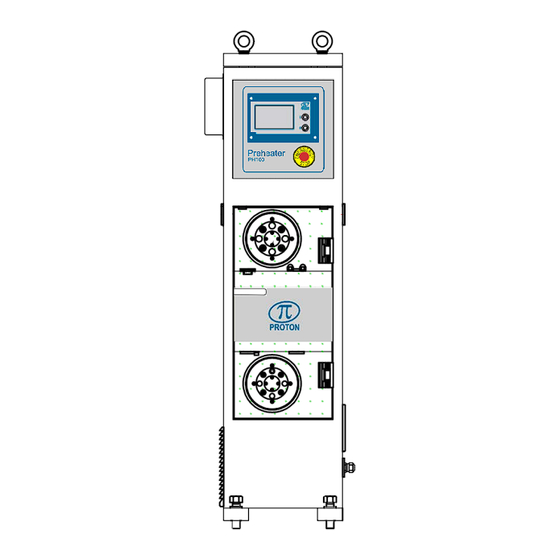
Page 14: Annotated Drawings
NNOTATED DRAWINGS Right side view Front view Description Lifting eyelet (×4 positions) Interface and communications wiring box Emergency stop button Interface display unit Circuit breakers Wire inlet / outlet Mains isolator switch Shorting pulley (copper rim) Mains power cable clamp Door handle (locked position shown) Door Air inlet grill... -
Page 15: Precautions
RECAUTIONS Operating temperature range Specification Minimum Typical Maximum Units °C Operating temperature +113 °F • Do not operate the unit in temperatures outside the above range or position the unit near high temperature surfaces or objects which may cause it to overheat. Protect from impact and movement •... -
Page 16: Nstallation
NSTALLATION Unpack the unit and check for missing accessories and shipping damage. ECHANICAL NSTALLATION • Locate the unit at least 0.3m from the extruder. • The maximum distance between the unit and the extruder increases with wire size and line speed;... -
Page 17: Pulley Installation
Pulley installation Normal pulley Attach the pulley to the pulley plate and tighten it using an M20 nut. Attach the pulley plate to the preheater using the indicated fixings. Quantity Part name Type Hex socket head cap screw M5× 25 Spring washer Ø5 Flat washer... - Page 18 Low loss pulley Attach each pulley to the pulley plate using M5× 8 screws. Attach each pulley plate to the mounting plate using M5×12 screws. PH160 Series MKII Wire Preheater Instruction Manual - Issue 6a Page 18...
- Page 19 Attach the mounting plate to the preheater using the indicated fixings. Quantity Part name Type Hex socket head cap M5× 16 screw Spring washer Ø5 Flat washer Ø5 PH160 Series MKII Wire Preheater Instruction Manual - Issue 6a Page 19...
-
Page 20: Lectrical Nstallation
LECTRICAL NSTALLATION 1. Install the 3-phase mains power supply cable. 2. Install communication interface connections as required (CAN, I-BUS, RS232/485, EIP). 3. Install electrical interface connections as required (DOOR LOCK, EMERGENCY STOP, START/STOP, ANALOGUE O/P, RELAY O/P). 4. Power on and configure the preheater via the interface display unit or communication interfaces. - Page 21 Unscrew the 6 screws indicated by the Insert the 3-phase mains supply cable arrows and remove the cover plate. through the cable clamp. Cover plate Earth Cable clamp Attach the four conductors to the terminal block as shown. Note: the earth wire must be connected to the terminal painted yellow and green. Standard models Canadian CSA compliant models Do NOT disconnect these wires...
- Page 22 Communication and electrical interface connections The communication and electrical interfaces are located in a junction box on the left side of the preheater. • Remove the four screws as indicated by the arrows to access the junction box. • A cable exit port is located on the rear face of the junction box. Junction Cable exit...
-
Page 23: Powering The Unit On Or Off
Powering the unit on or off The unit may be powered on or off by turning the mains isolator switch located on the right side of the unit. Mains isolator switch Power on indications LED status Indication Power LED (located in the communication and electrical interfaces Unit is powered on junction box) Extinguished... -
Page 24: Interface Display Panel
INTERFACE DISPLAY PANEL The interface display panel located on the front of the preheater is a colour touch screen using for the preheater conditions display and parameters configuration. Preheating switch button / ON Preheating switch button / OFF The two buttons located on the front of the interface display panel are preheating switches. Press “ON” button to start preheating or “OFF”... -
Page 25: Configuration Interface
CONFIGURATION INTERFACE HOME PAGE The home page is used for monitoring the preheating process and displaying the following data: • Preset wire temperature, material and cross-sentional area. • Wire temperature calculated from the delivered electrical power. • Measured loop voltage and current as a percentage. •... - Page 26 Preheating disabled. Preheating enabled and running (“LINE SPEED” > “Start speed”). Preheating enabled but not running (“LINE SPEED” < “Start READY speed”). Press to lock the optional electric door lock and start preheating (set preheater status to “READY” or “ON”). Press to stop preheating (set preheater status to “OFF”) and unlock the optional electric door lock.
- Page 27 Press the button to advance to next Preset page for wire material setting. To configure the preheater for operation with To configure the preheater for operation with copper (including solid copper, tin-plated copper copper-clad wire: or silver-plated copper) or aluminium wire: To configure the preheater for operation with wire materials other than copper, aluminium or copper- clad: Label...
-
Page 28: Function Menu
Press the button to advance to next Preset page to preset the input temperature. If the input temperature type is set to “Preset” on System page 3, the preset input temperature value can be set on this page. FUNCTION MENU Press the Home icon to return to the home page;... -
Page 29: System
SYSTEM Press the System icon on the function menu page to access System-Tuning page. Label Description Set the tuning gain to compensate the wire temperature at high line speed (> 2 Gain 0 ~ 999 × minimum speed). Set the tuning zero to compensate the wire temperature at low line speed (< 2 × Zero 0 ~ 999 minimum speed). -
Page 30: Wire Break Detection
Press the button on System page 1 to advance to System page 2. Label Description Disable wire break detection. Wire break Enable wire break detection. Wire break time 0~65535ms Set the wire break delay time. In “Auto [Area]” mode, the wire range will be automatically Auto[Area] calculated by the wire size set on Preset page 1. - Page 31 Press the button on System page 2 to advance to System page 3. Label Description The preheater inlet cable temperature is ambient Ambient temperature. Input temperature type The preheater inlet cable temperature can be preset on Preset “Preset” page. Door Open The light in the preheater will be on when the door is open.
- Page 32 Label Description Group number Enter the group number (0~50). Save Click this button to save changes to the current active group after modifying the input parameter values (This button will disappear when the Group store authority was set to “Locked” on the Access level page). Recall Click this button to recall the stored input parameter values in the group.
- Page 33 Press the button on System page 4 to advance to System page 5. Label Description Unit Select the unit from options: Metric; Imperial. Language Select the language from options: English; French. Factory default Click this button to restore all parameters to factory default settings. Press the button on System page 5 to advance to System page 6, 7.
-
Page 34: Communications
RS232 baud rate Select the RS232 baud rate from options: 4800; 9600; 19200; 38400; 115200. RS422 protocol Select the RS422 protocol from options: PROTON; Modbus; MD5 TG. RS422 baud rate Select the RS422 baud rate from options: 4800; 9600; 19200; 38400; 115200. - Page 35 Label Description Disabled Disable DHCP allocation of the Ethernet IP address. DHCP Enabled Enable DHCP allocation of the Ethernet IP address. IP address Enter the IP address assigned to the preheater. Subnet mask Enter the subnet mask for the network. Gateway Enter the gateway address for the network.
-
Page 36: Interface
INTERFACE Press the Interface icon on the function menu page to access Interface page 1 and 2 for the analogue output configuration. Label Description Select the analogue output 1 (2,3,4) function from options: Loop Voltage; A1 (A2,A3,A4) function Loop Current; Wire Temperature; Primary Voltage; Primary Current; Line speed. -
Page 37: Access Levels
“FB TEMP” input. Preheating temperature is controlled by a PROTON TG PROTON Temperature Gauge. Preheating temperature is controlled by an MD5 MD5 TG Temperature Gauge. Set the temperature control full scale value (only if “External Analogue”... - Page 38 Input the password “18018” then select to lock or unlock the respective pages. The “Access level” menu is a password protected menu which controls which parameters may be adjusted by the operator. • It is recommended that parameters are re-locked after configuration to prevent unwanted changes being made during production.
-
Page 39: Operation
PERATION OLENOID ANUAL VERRIDE Preheaters fitted with the solenoid door lock must be powered on, with the preheater state set to “OFF” and with both pulleys stationary before the solenoid door lock will unlock, otherwise the door cannot be opened. In the absence of electrical power, Preheaters fitted with solenoid door locks will be locked. - Page 40 Open the lower rear door, locate the lock override holes and unscrew the black plastic blanking plugs: PH160 Series MKII Wire Preheater Instruction Manual - Issue 6a Page 40...
- Page 41 Insert the unlock tool into the hole until it is engaged and rotate the tool 180° to UNLOCK the doors: PH160 Series MKII Wire Preheater Instruction Manual - Issue 6a Page 41...
- Page 42 PH160 Series MKII Wire Preheater Instruction Manual - Issue 6a Page 42...
- Page 43 WARNING: The manual override mechanism does NOT automatically revert to the locked state after unlocking. Do NOT operate the preheater with the doors overridden to the always unlocked state. After using the manual override procedure to unlock the doors, ALWAYS restore the locks to the locked state using the following procedure: Insert the unlock tool into the hole until it is engaged and rotate the tool 180°...
-
Page 44: Wire Threading
HREADING The wire may be run in either direction (left-to-right or right-to-left) through the preheater. Thread the wire in the following sequence: User Action Insert the wire horizontally through the wire inlet port. Run the wire over and around the BACK groove of the upper shorting (copper) pulley. CAUTION: The rim of this pulley may be hot;... - Page 45 Wire threading for three pulleys: Core Core Core Core Sufficient tension must be applied to the wire so that it does not touch either transformer tube and is correctly seated in the pulley grooves. Good contact between the wire and the upper shorting (copper) pulley groove is also necessary to prevent sparking and damage to the pulley surface.
-
Page 46: Start - Up Configuration
TART UP CONFIGURATION Step Action Interface display unit Set the wire material “Preset” page 2 or 3 Set the preheating temperature “Preset” page 1 Set the start speed “System” page 2 Set the wire size range (in “Manual” mode) or enter the wire size (in “Auto” “Preset”... -
Page 47: Troubleshooting
(e.g from 4 to 3). Allow the preheater to cool IGBT overheat down before resuming operation. Contact your Proton Products IGBT failure. service representative. Contact your Proton Products Mains power supply fault service representative. The solenoid door lock is... - Page 48 IGBT driver modules. Inspect mains power supply Mains power supply phase for phase loss and remedy loss. accordingly. Coupling capacitor voltage at Contact your Proton Products maximum value. service representative. PH160 Series MKII Wire Preheater Instruction Manual - Issue 6a Page 48...
-
Page 49: Communication Interfaces
This CAN-bus interface is fitted as standard. It operates independently of the other communication interfaces and may be used at the same time as them. The CAN-bus interface uses a proprietary Proton Products protocol. It is exclusively used to communicate between the unit and other Proton Products modules. The unit automatically detects connection to other modules and configures the bus appropriately;... -
Page 50: I-Bus Communications
I-BUS COMMUNICATIONS This I-BUS communication interface operates independently of the other communications interfaces and may be used at the same time as them. This I-BUS interface supports four types of standard industrial bus interfaces, DeviceNet, PROFIBUS, PROFINET and EtherNet/IP for connection to PLCs and other process control instrumentation. The I-BUS communication interface may be end-user enabled through the purchase of a license key. -
Page 51: Rs232/Rs422 Communications
RS232/RS422 C OMMUNICATIONS This RS232/422 interface is fitted as standard. It operates independently of the other communication interfaces and may be used at the same time as them. RS232/RS422 Interface The RS232/422 interface may be accessed through the “RS232/RS422” connector. Connector type: DB9 female Comment RS232... -
Page 52: Ethernet Communications
THERNET COMMUNICATIONS This Ethernet interface is fitted as standard. It operates independently of the other communications interfaces and may be accessed at the same time as them. Ethernet interface The Ethernet interface may be accessed through the RJ45 connector. Connector type: RJ45 8P8C female Designation Comments LAN TX+... -
Page 53: Lectrical Nterfaces
LECTRICAL NTERFACES DOOR LOCK Under normal operation, the solenoid door lock is automatically controlled by the preheater software; no external connection should be made to the lock control input. If it is necessary to open the door when the preheater is not connected to a mains power supply, then connecting a +24V DC power supply across the “DOOR LOCK”... -
Page 54: Start/Stop
START/STOP Preheating may be remotely started and stopped by voltages applied to the “START/STOP” interface. START/STOP Interface Electrical connection The “START/STOP” interface may be accessed through the “START/STOP” screw terminal block: START/STOP θ ■ Factory-installed shorting link θ The preheater unit is factory-fitted with a shorting link between terminal “+V” and “ ”... - Page 55 START and STOP inputs behaviour Input state Preheater state START STOP LOW / unconnected LOW / unconnected Stop LOW / unconnected HIGH Set by interface display panel HIGH LOW / unconnected Stop HIGH HIGH Start For operation using the interface display panel only: •...
-
Page 56: Analogue O/P
ANALOGUE O/P The analogue interface provides 4 analogue voltage outputs corresponding to: • Loop voltage • Loop current • Wire temperature • Primary voltage • Primary current • Line speed ANALOGUE O/P interface Electrical connection The analogue outputs may be accessed through the “ANALOGUE O/P” screw terminal block: Connector type: screw terminal block Designation Description... -
Page 57: Emergency Stop
EMERGENCY STOP Operation of the preheater may be enabled or disabled by a voltage applied to the “EMERGENCY STOP” interface. EMERGENCY STOP interface Electrical connection Connector type: Screw terminal block Designation Description +24V output voltage Emergency stop input (in normal condition, this terminal is shorted to +24V; when pressing the emergency stop button, the emergency stop function will be enabled to stop the preheater;... -
Page 58: Relay O/P
ELAY Four relay outputs are fitted as standard for indication of preheater state and fault conditions. RELAY O/P interface Electrical connection The 4 relay outputs may be accessed through the “RELAY O/P” screw terminal block. Connector type: Screw terminal block Designation Description Each individual relay output can be independently configured to... -
Page 59: Temperature Set Input (Set Temp)
(SET TEMP) EMPERATURE SET INPUT The preheating temperature may be remotely set by an analogue voltage applied to the “SET TEMP” input. SET TEMP interface Electrical connection The “SET TEMP” input may be accessed through the screw terminal block. Connector type: Screw terminal block Designation Description Notes... -
Page 60: Measured Temperature Feedback Input (Fb Temp)
(FB TEMP) EASURED TEMPERATURE FEEDBACK INPUT The preheating temperature is adjusted to approach the set temperature value according to the signal generated by the temperature device connected to the “FB TEMP” interface. FB TEMP interface Electrical connection The “FB TEMP” input may be accessed through the screw terminal block. Connector type: Screw terminal block Designation Description... -
Page 61: Interface Terminal Block
NTERFACE TERMINAL BLOCK Designation Description Functional group ■ Not connected DOOR LOCK Apply 24V to unlock the door Door lock control input Ground reference +24V (drive signal for logic inputs) ■ Ground reference Start preheating input Stop preheating input (this Logic inputs (not isolated from START/STOP terminal is shorted by a factory-... - Page 62 Relay contact outputs (all RELAY O/P User programmable isolated from earth and voltage- free) 0 to +10V control voltage input SET TEMP Temperature set voltage input Ground reference 0 to +10V control voltage input FB TEMP Feed-back temperature input Ground reference DB9 (male) CAN-bus communications I-BUS...
-
Page 63: Wiring Diagram (Ce / Csa Compliant Models )
(CE / CSA IRING DIAGRAM COMPLIANT MODELS PH160 Series MKII Wire Preheater Instruction Manual - Issue 6a Page 63... -
Page 64: Proton Standard Rs-232 Parameter Access Protocol
• Output parameters are read only and provide access to preheater status and measured data. They may be requested to stream continuously from the preheater. The Proton standard RS-232 protocol data format is as follows: Number of data bits Parity... -
Page 65: Modbus Parameter Access Protocol
ODBUS PARAMETER ACCESS PROTOCOL This protocol provides access to individual parameters or blocks of parameters and is typically used in a production environment where the Proton Products instrument is connected to a computer, Modbus connected PLC or similar device. The parameters consist of 16-bit words (DW) and are divided into input and output groups: •... -
Page 66: Input Parameters
NPUT PARAMETERS Range of input parameters accessible by Interface Interface Lowest DW Highest DW Length/words PROFI/ /EtherNet/IP Master to Slave CAN-bus / RS-232 / RS-422/485 / Ethernet 1x 16-bit word = 2x 8-bit bytes Comments Unit Range/Remark Default Value Heating Switch 0=OFF;1=ON Preset Temperature 1=1°C{°F}... - Page 67 Comments Unit Range/Remark Default Value Temprerature too high Relay 2 Function Relay 3 Function Relay 4 Function 0=Auto[Area]; Wire Size Range 1=Auto[AWG] Selection Mode 2=Manual Analogue OP1 0=Loop Function Voltage;1=Loop Analogue OP2 Current;2=Wire Function Temperature;3=Pri Analogue OP3 mary Function Voltage;4=Primary Current;5=Line Analogue OP4 Speed;...
- Page 68 0~125 CAN Address 0~255 0=250; 1=500; CAN Baud Rate 2=1000; other=500 CAN Terminator 0=OFF;1=ON 0=4800;1=9600;2= RS232 Baud Rate 19200;3=38400;4= 115200 0=Proton; RS232 Mode 1=Modbus 0=Proton; RS422/RS485 Mode 1=Modbus; 0=4800;1=9600;2= RS422/RS485 Baud 19200;3=38400;4= Rate 115200; 0=Disabled;1=Enab ETH DHCP C0A801A0(19 ETH IP Address 2.168.1.160)
- Page 69 Comments Unit Range/Remark Default Value Destination IP Port number fixed address for UDP to 1111 (last section only) MAC address for Ethernet PH160 Series MKII Wire Preheater Instruction Manual - Issue 6a Page 69...
-
Page 70: Output Parameters
UTPUT PARAMETERS 1x 16-bit word = 2x 8-bit bytes Comments Units Range/Remark Preheater Status 0=OFF,1=ON,2=Ready Reserved Unit 0=Metric;1=Imperial Type of preset temperature 0=Preset input input,1=Analogue input State of Door 1=Closed,0=Opened State of Lock 1=Locked,0=Unlocked Mains Relay 1=Closed,0=Opened Relay 1 1=Closed,0=Opened Relay 2 1=Closed,0=Opened Relay 3... - Page 71 Comments Units Range/Remark 1=1°C Wire Temperature 0~999 1=1% Heating Voltage 0~9999 1=1% Heating Current 0~9999 1=1m/min{ft/min) Line speed 0~3000 1=0.1°C Ambient Temperature 0~99 1=1°C Preset Temperature 0~999 Reserved Reserved 1=0.001mm2{0.0001in2} Range 1 Wire Size 0.000~99.000 Range 2 Wire Size 0.000~99.000 Range 3 Wire Size 0.000~99.000 Range 4 Wire Size...
-
Page 72: Sales And Service
Proton Products is not responsible for consequential or incidental damage related to the provision or use of the information contained in this manual. • The information contained in this manual is the property of Proton Products and may not be circulated or distributed to third parties. •...
Need help?
Do you have a question about the InteliSENS PH160 MKII Series and is the answer not in the manual?
Questions and answers