Table of Contents
Advertisement
Quick Links
This Owner's Manual is provided and hosted by Appliance Factory Parts.
White Mountain Hearth
DVCC42BP7P-3
Owner's Manual
Shop genuine replacement parts for White Mountain
Hearth DVCC42BP7P-3
Find Your White Mountain Hearth Fireplace Parts - Select From 539 Models
-------- Manual continues below --------
Advertisement
Table of Contents
Troubleshooting

Related Manuals for Empire Comfort Systems DVCC42BP7P-3


Summary of Contents for Empire Comfort Systems DVCC42BP7P-3
- Page 1 This Owner's Manual is provided and hosted by Appliance Factory Parts. White Mountain Hearth DVCC42BP7P-3 Owner's Manual Shop genuine replacement parts for White Mountain Hearth DVCC42BP7P-3 Find Your White Mountain Hearth Fireplace Parts - Select From 539 Models -------- Manual continues below --------...
-
Page 2: Installation Instructions
INSTALLATION INSTRUCTIONS INSTALLER: DIRECT VENT Leave this manual with the appliance. ZERO CLEARANCE GAS CONSUMER: FIREPLACE HEATER SERIES Retain this manual for future reference. MILLIVOLT (MV) DVCC(32,36,42)BP3(0,2)(N,P)-3 WARNING INTERMITTENT PILOT (IP) FIRE OR EXPLOSION HAZARD DVCC(32,36,42)BP7(0,2)(N,P)-3 Failure to follow safety warnings exactly could result in serious injury, death or property damage. -
Page 3: Table Of Contents
TABLE OF CONTENTS SECTION PAGE ATTENTION INSTALLER ......................3 BEFORE YOU START ........................4-5 CARTON CONTENTS ........................6 INTRODUCTION ........................... 7 HOMEOWNER REFERENCE INFORMATION ................7 SPECIFICATIONS ......................... 8 ACCESSORIES ..........................9 FIREPLACE DIMENSIONS ......................10 FBB10 BLOWER KIT INSTALLATION (OPTIONAL) .............. 11-13 CLEARANCES .......................... -
Page 4: Attention Installer
ATTENTION INSTALLER: Fireplace Installation Checklist Use this checklist in conjunction with the instructions in this manual. Customer: _____________________________________ Date Installed: __________________________________ Lot/Address: ___________________________________ Fireplace Location: ______________________________ _______________________________________________ Installer: _______________________________________ Model: ________________________________________ Dealer Phone #: _________________________________ Serial # ________________________________________ FIREPLACE INSTALLATION COMMENTS ____________________ Verified clearances to combustibles (pg. -
Page 5: Before You Start
Improper positioning of logs, glass door, or accessories. • Installation and/or use of any component part not manufactured or approved by Empire Comfort Systems. All correspondence should refer to complete Model Number, Serial Number and type of gas. Fill out the Homeowner Reference Section. - Page 6 BEFORE YOU START (CONTINUED) Preparation Accessories This fireplace and its components are safe when installed Most accessories install much more easily before fitting the in accordance with this Manual. Report any parts damaged fireplace to the opening. in shipment to your dealer. Do not install the fireplace with For example, it takes just 10-15 minutes to install the blower side damaged, incomplete or substitute parts.
-
Page 7: Carton Contents
CARTON CONTENTS NOTICE: Items not shown to scale. QUANTITY SUPPLIED INDEX DESCRIPTION DVCC(32,36,42)BP3 DVCC(32,36,42)BP7 NUMBER SERIES SERIES Rock Wool Receptacle Cover Receptacle Flue Restrictor Assembly - (See Page 30) 10 X 1/2 Phillips Screw #8 X 1 Self-Drilling Drywall Screw AA Battery AC Adaptor Backer Stud... -
Page 8: Introduction
INTRODUCTION Fireplace Certification The information in this manual pertains to all models and gas control systems unless otherwise noted. This fireplace is design certified in accordance with American National Standard/CSA Standard ANSI Z21.88/CSA 2.33 and by Instructions to Installer Underwriters Laboratories as a Direct Vent Gas Fireplace Heater Leave this manual with homeowner. -
Page 9: Specifications
SPECIFICATIONS DVCC32NAT DVCC32LP DVCC36NAT DVCC36LP DVCC42NAT DVCC42LP Input BTU/Hr Maximum 24,000 22,000 24,000 24,000 26,500 26,500 Input BTU/Hr Minimum (millivolt only) 18,000 18,000 18,000 19,000 18,000 22,000 KWH (Maximum) 7.03 6.45 7.03 7.03 8.35 7.77 KWH (Minimum) 5.27 5.27 5.28 5.57 6.15 Orifice... -
Page 10: Accessories
ACCESSORIES The following accessory parts can be obtained from your Empire Comfort Systems dealer. If you need additional information beyond what your dealer can furnish, contact Empire Comfort Systems Inc., 918 Freeburg Ave., Belleville, Illinois 62220-2623. OPTIONAL Model Number Description... -
Page 11: Fireplace Dimensions
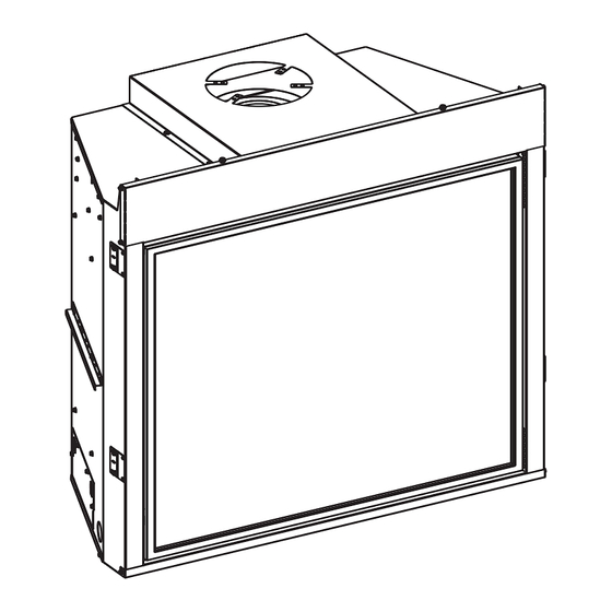
FIREPLACE DIMENSIONS TOP VIEW LEFT VIEW RIGHT VIEW FRONT VIEW GAS LINE ACCESS GAS LINE ACCESS TOP STANDOFF VENT COLLAR NAILING FLANGES BARRIER SCREEN ASSEMBLY & GLASS FRAME ASSEMBLY SIDE STANDOFF GAS CONTROL AND SWITCHES INSIDE RATING PLATE AND GAS LINE LABELS INSIDE ACCESS DVCC32... -
Page 12: Fbb10 Blower Kit Installation (Optional)
FBB10 BLOWER KIT INSTALLATION (OPTIONAL) BEFORE FIREPLACE IS INSTALLED IN WALL AFTER FIREPLACE IS INSTALLED IN WALL With power completely turned off, remove plate and four NOTICE: Do not handle barrier screen or door assembly screws from left panel. See Figure 1. with your bare hands! (Always Wear Gloves) Turn off power and gas. - Page 13 FBB10 BLOWER KIT INSTALLATION (OPTIONAL) (CONT’D) Remove the modern cover by lifting off. See Figure 7. Remove burner cover by lifting off. See Figure 10. (At installation modern cover is behind valve) Figure 10 Figure 7 Remove log support by unscrewing two screws securing the Remove the two screws securing the liner brackets to the metal plate to the log support.
- Page 14 FBB10 BLOWER KIT INSTALLATION (OPTIONAL) (CONT’D) 10. Remove ten screws and lift burner assembly. Disconnect the 14. Reinstall the left latch assembly removed in step 11. gas line. See Figure 13. See Figure 14. 15. Install thermo disc by snapping into valve bracket burner assembly.
-
Page 15: Clearances
CLEARANCES Mantel Chart CLEARANCE TO COMBUSTIBLES (Inches) Back Side Floor Top Framing Edge See Below SEE MANTLE CHART FOR MAXIMUM MANTEL DEPTH 2" x 4" HEADER FINISHED WALL (COMBUSTIBLE) FIREPLACE OPENING 24” MINIMUM TO SEE MANTEL CHART CHASE TOP FOR MINIMUM HEIGHT 9”... -
Page 16: Termination Clearances
Clearances are to heat resistant material (i.e. wood, metal). This Important! When vent termination exits through foundation less does not include vinyl. Empire Comfort Systems Inc. will not be held than 20 inches (508 millimeter) below siding outcrop, the vent... -
Page 17: Vent Terminal Clearances
Clearances are to heat resistant material (i.e. wood, metal). This of the following shall be indicated: does not include vinyl. Empire Comfort Systems Inc. will not be Clearance in accordance with local installation codes and the requirements of the held responsible for heat damage caused from terminating under gas supplier. -
Page 18: Gas Supply
GAS SUPPLY The gas pipeline can be brought in through the right or left side of The gas lines must be checked for leaks by the installer. This should the appliance. Consult the current National Fuel Gas Code, ANSI be done with a soap solution watching for bubbles on all exposed Z223.1 CAN/CGA-B149 (.1 or .2) installation code. -
Page 19: Safety Information For Users Of Lp Gas
SAFETY INFORMATION FOR USERS OF LP GAS Propane (LP-Gas) is flammable and can cause fires LP-Gas may stratify in a closed area, and the odor intensity and explosions. In its natural state, propane is odor- could vary at different levels. Because it is heavier than air, less and colorless. -
Page 20: Locating Fireplace
LOCATING FIREPLACE NOTICE: Island and Room Divider installation is possible as long as the horizontal portion of the vent system does not exceed 20 feet with a minimum vertical run of 8 feet. See details in Venting Section. When you install your Direct Vent Fireplace in Room divider or Flat on wall corner positions, a minimum of 6 inches clearance must be maintained from the perpendicular wall and the front edge of the appliance. -
Page 21: Millivolt Standing Pilot Wiring Diagram
MILLIVOLT STANDING PILOT WIRING DIAGRAM (BP3 SERIES) WIRING If any of the original wire supplied with this unit must be replaced. Use no. 18, 150°C wire or its equivalent. R10947 Figure 30 Page 20 37606-0-1116... -
Page 22: Ipi Electronic System Wiring Diagram
IPI ELECTRONIC SYSTEM WIRING DIAGRAM (BP7 SERIES) BLUE BLUE GREEN WHITE WHITE ORANGE CPI/IPI SWITCH ON/OFF REMOTE RECEIVER PILOT SWITCH (OPTIONAL) YELLOW (INCLUDED) + ON REMOTE - OFF ORANGE WHITE GAS CONTROL VALVE (GND) WHITE GREEN BLACK AC/DC POWER ADAPTOR R11034 BLACK ELECTRONIC... -
Page 23: Installation
INSTALLATION You must install certain components before the fireplace is FRAMING THE FIREPLACE permanently installed. These include the direct-vent system, gas Choose fireplace location. piping for the appliance and the electrical wiring. (If the optional Frame in fireplace with a header across the top. It is important blower is used). - Page 24 INSTALLATION (continued) VENT PIPE CLEARANCE For horizontal vent, maintain a minimum 2 inch clearance to the bottom and sides of the vent, and 3 inch clearance to combustibles above the vent pipe. See Figures 36 and 37. BACKER STUD VENT PIPE BLACK FIREPLACE FRONT BACKER STUD...
- Page 25 INSTALLATION (continued) FLUSH WALL INSTALLATION 2 X 4 FINISHED WALL HEADER (COMBUSTIBLE) FINISHED WALL 24” (NON-COMBUSTIBLE) TO TOP OF CHASE JOINT BETWEEN FINISHED WALL AND UNIT SEALED WITH 300° F, 149° C SEALANT MATERIAL (SEALANT IS OPTIONAL) FRONT TRIM OR NON-COMBUSTIBLE MATERIAL (INSTALLATION IS OPTIONAL) Figure 38...
- Page 26 INSTALLATION (continued) VERTICAL, 90-DEGREE ELBOW TO HORIZONTAL OUT THE NOTICE: Cold climate installation recommendation: When WALL (12 inch minimum rise before elbow) installing this unit against a non-insulated exterior wall, it must “A” 90° ELBOW conform to applicable codes. PIPE LENGTH VERTICAL, 90-DEGREE ELBOW WITH HORIZONTAL TERMINATION...
-
Page 27: Vent Framing
VENT FRAMING Installing Support Brackets Installing Firestops Install a horizontal pipe support used for each 3 feet of horizontal Firestops are required for safety whenever the vent system passes run to framing members. Allow 6 inch clearance to combustibles through a wall or a ceiling. These firestops act as a firebreak heat above vent pipe and elbows and 2 inch clearance on both sides shield and as a means to ensure minimum clearances are maintained and bottom. - Page 28 VENT FRAMING (continued) Vertical Firestops Vertical vent runs which pass through ceilings require one ceiling firestop at the hole in each ceiling through which the vent passes. Position a plumb bob directly over the center of the vertical vent component and mark the ceiling to establish the center point of the vent.
-
Page 29: Vent System Identification
THREE 90 ELBOWS 45° ELBOW ROOF FLASHING 90° ELBOW Special Venting Components (Duravent) See Empire Comfort Systems Retail Price List for Venting part CEILING FIRE STOP numbers and pricing. WALL STRAP SPECIAL DV VENT KITS Available from Empire Comfort Systems, Inc. dealers... -
Page 30: Venting Fireplace - Top
VENTING FIREPLACE - TOP Venting Graph (Dimensions in Feet) To Use the Vent Graph Determine the height of the center of the horizontal vent pipe. TOP EXIT - VERTICAL AND HORIZONTAL TERMINATION Using this dimension on the Sidewall Vent Graph, locate the (DIMENSIONS IN FEET) point it intersects with the slanted graph line. - Page 31 VENTING FIREPLACE - TOP (continued) Below-Grade Installation NOTICE When it is not possible to meet the required vent termination clearances of 12 inches (305 millimeters) above grade level, a Use flue restrictor for vertically terminated units only. Do snorkel kit is recommended. It allows installation depth down not use for horizontally terminated units.
- Page 32 VENTING FIREPLACE - TOP (continued) Example of venting system using one 90-degree elbow Eight feet is minimum vertical vent run with 20 feet of maximum horizontal vent run. Vertical dimensions are based on center-line to center-line of pipe. Horizontal dimensions are based on center line of pipe to end of termination.
- Page 33 VENTING FIREPLACE - TOP (continued) Positioning the Fireplace 3’ Determine the exact position of the appliance so the direct-vent (914mm) termination will be centered (if possible) between two studs. This will avoid any extra framing. Assemble the vent pipes on the unit after it is moved into the final position.
-
Page 34: Examples - Top Vent Run
EXAMPLES - TOP VENT RUN ” ► 24” MINIMUM CLEARANCE TO COMBUSTIBLES ► EXAMPLE H1 = 2ft V1 = 20ft H=2ft V = 20ft ▼ Figure 59 Figure 61 Example H2 – 3ft, H3 – 1ft = 4ft (90° + 90° + 90°) = 6ft V1 = 21ft H = 10ft V = 21ft Figure 60... -
Page 35: Horizontal Termination
HORIZONTAL TERMINATION One 90-Degree Elbow Two 90-Degree Elbows NOTICE: Subtract 3 feet from the total horizontal INSTALLED VERTICALLY measurement for each 90-degree elbow installed horizontally. Subtract 1-1/2 feet from the total horizontal measurement for each 45-degree elbow installed horizontally. INSTALLED 1’... -
Page 36: Vertical Termination
VERTICAL TERMINATION Locate and mark the center point of the vent pipe using a nail on General Maintenance the underside of the roof. Drive the nail through the center point. Inspect venting system semi-annually as follows: Mark the outline of the roof hole around this center point. 1. - Page 37 VERTICAL TERMINATION (continued) Vertical Through the Roof Applications Your Gas Fireplace has been approved for: a) Vertical installations up to 40 feet in height. b) Two sets of 45 degree elbow offsets within these vertical installations. From 0 to a maximum of 8 feet a vent pipe can be used between elbows.
- Page 38 DVVK-4F FLEX VENT INSTRUCTIONS FOR HORIZONTAL TERMINATION The following termination kits can only be used with direct vent fireplaces listed for use with Magnaflex DVVK-4F. Please check and verify your fireplace model number. DVVK4F 4-in./7-in. - 48-in. FLEX TERMINATION KIT Item Termination Cap 3”...
-
Page 39: Dvvk-4F Flex Vent Instructions
DVVK-4F FLEX VENT INSTRUCTIONS FOR HORIZONTAL TERMINATION (CONT’D) Determine the length of the vent needed, allowing slightly more sold separately) then insert the adapter collar to the flue vent then required. Stretch the inner and outer flex vent out to collar on the fireplace. -
Page 40: Millivolt Standing Pilot Lighting Instructions
MILLIVOLT STANDING PILOT LIGHTING INSTRUCTIONS (BP3 SERIES) FOR YOUR SAFETY READ BEFORE LIGHTING WARNING If you do not follow these instructions exactly, a fire or explosion may result causing property damage, personal injury or loss of life. A. This appliance has a pilot which must be lighted by C. -
Page 41: Millivolt Operating Instructions
MILLIVOLT OPERATING INSTRUCTIONS (BP3 SERIES) Millivolt System STANDING PILOT OPERATING INSTRUCTIONS The standing pilot burns continuously even when the main burner is OFF. REMOTE OFF/ON SWITCH When you ignite the pilot, the thermopile produces millivolts (electrical The fireplace is equipped with a REMOTE OFF/ON switch. A wire current) which energizes the magnet in the gas valve. -
Page 42: Millivolt Standing Pilot Troubleshooting
MILLIVOLT STANDING PILOT TROUBLESHOOTING (BP3 SERIES) With proper installation and maintenance, your new Direct-Vent Gas Fireplace will provide years of trouble-free service. If you do experience a problem, refer to the Troubleshooting Guide below. This guide will assist a qualified service person in diagnosis and corrective action. -
Page 43: Intermittent Pilot Lighting Instructions
INTERMITTENT PILOT LIGHTING INSTRUCTIONS (BP7 SERIES) FOR YOUR SAFETY READ BEFORE LIGHTING WARNING If you do not follow these instructions exactly, a fire or explosion may result causing property damage, personal injury or loss of life. This appliance has a pilot which can be lighted with the C. -
Page 44: Ipi Electronic System Operating Instructions
IPI ELECTRONIC SYSTEM OPERATING INSTRUCTIONS (BP7 SERIES) ELECTRONIC CONTROL VALVE OPTIONAL REMOTE CONTROLS The electronic control valve system includes the ability to switch Optional remote controls are available for use with this appliance. the pilot from a standing pilot mode to an intermittent pilot mode. It is recommended that the remote receiver be placed either IPI Mode - In the Intermittent Pilot mode, when the unit •... -
Page 45: Intermittent Pilot Control System Troubleshooting
INTERMITTENT PILOT CONTROL SYSTEM TROUBLESHOOTING PROBLEM OBSERVED POSSIBLE CAUSE CORRECTIVE MEASURE See “What to do if you smell gas” Page 1. Gas odor during setup Gas Leak Check all gas connections. Tighten all loose connections. See “What to do if you smell gas” Page 1. Gas odor before first ignition Gas Leak Check all gas connections. - Page 46 INTERMITTENT PILOT CONTROL SYSTEM TROUBLESHOOTING (CONT’D) PROBLEM OBSERVED POSSIBLE CAUSE CORRECTIVE MEASURE Low gas pressure Check gas supply pressure Loose sensor wire Check wire connection Faulty valve Replace valve Faulty pilot or thermocouple Replace Safety pilot Burner lights but does not stay Clogged or dirty burner ports Clean burner ports lit while pilot remains on...
-
Page 47: Millivolt Parts View - Dvcp(32,36,42)Bp3
MILLIVOLT PARTS VIEW - DVCC(32,36,42)BP3 31 32 29 30 SOME COMPONENTS MAY DIFFER FROM SHOWN. Page 46 37606-0-1116... -
Page 48: Millivolt Parts List - Dvcp(32,36,42)Bp3
MILLIVOLT PARTS LIST - DVCC(32,36,42)BP3 PART NUMBER PART NUMBER INDEX INDEX DESCRIPTION DESCRIPTION DVCC32 DVCC36 DVCC42 DVCC32 DVCC36 DVCC42 P286 P286 ORIFICE #42 NAT 35918 35918 35918 INSULATION BOX P208 ORIFICE #1.45mm LP INSULATION TOP, R12177 R12177 R12177 CENTER P258 ORIFICE #1.55mm LP BRACKET, SHIPPING P323... -
Page 49: Ip Parts View - Dvcp(32,36,42)Bp7
IP PARTS VIEW - DVCC(32,36,42)BP7 31 32 29 30 34 35 SOME COMPONENTS MAY DIFFER FROM SHOWN. Page 48 37606-0-1116... -
Page 50: Ip Parts List - Dvcp(32,36,42)Bp7
IP PARTS LIST - DVCC(32,36,42)BP7 PART NUMBER PART NUMBER INDEX INDEX DESCRIPTION DESCRIPTION DVCC32 DVCC36 DVCC42 DVCC32 DVCC36 DVCC42 35918 35918 35918 INSULATION BOX P286 P286 ORIFICE #42 NAT INSULATION TOP, P208 ORIFICE #1.45mm LP R12177 R12177 R12177 CENTER P258 ORIFICE #1.55mm LP BRACKET, SHIPPING 35997... -
Page 51: Maintenance And Service
• Never operate the fireplace with the glass removed or cracked. • Have your dealer replace damaged glass only with glass and gasket material from Empire Comfort Systems. Using substitute glass will void the warranty. Glass Cleaning Procedure Turn off the fireplace and allow it to cool for at least an hour. - Page 52 MAINTENANCE AND SERVICE (CONTINUED) Glass Door & Barrier Screen Removal Once the glass door is placed flat to the firebox front edges, engage the two spring latches to the bottom flange on the glass NOTICE: Do not handle barrier screen or door with your bare door frame to secure the door assembly.
-
Page 53: Important Safety Information - Installer
IMPORTANT SAFETY INFORMATION - INSTALLER Maintenance Precautions For the Installer Installation and repair should be done by a qualified service • Leave these instructions with the homeowner. person. The fireplace should be inspected before use and at • Replace any guard or protective device removed for least annually by a qualified service person. -
Page 54: Requirements For The Commonwealth Of Massachusetts
REQUIREMENTS FOR THE COMMONWEALTH OF MASSACHUSETTS For all side wall horizontally vented gas fueled equipment 3. SIGNAGE. A metal or plastic identification plate shall be installed in every dwelling, building or structure used in permanently mounted to the exterior of the building at a whole or in part for residential purposes, including those minimum height of eight feet above grade directly in line owned or operated by the Commonwealth and where the... -
Page 55: Annual Fireplace Inspection Checklist
ANNUAL FIREPLACE INSPECTION CHECKLIST > ANNUAL INSPECTION DATE Inspect pilot and burner system and replace any damaged parts Check glass gasket and door for proper seal Check barrier screen for proper fit and structural integrity Check latches for proper operation and tensions Inspect log set/decorative media for debris and damage Clean dust and debris from fireplace... -
Page 56: Master Parts Distributor List
This list changes from time to time. For the current list, please click on the Master Parts button at www.empirecomfort.com. Please note: Master Parts Distributors are independent businesses that stock the most commonly ordered Original Equipment repair parts for Heaters, Grills, and Fireplaces manufactured by Empire Comfort Systems Inc. Dey Distributing F. -
Page 57: Warranty
WARRANTY Empire Comfort Systems Inc. warranties this hearth product to be free from defects at the time of purchase and for the periods specified below. Hearth products must be installed by a qualified technician and must be maintained and operated safely, in accordance with the instructions in the owner’s manual.
Need help?
Do you have a question about the DVCC42BP7P-3 and is the answer not in the manual?
Questions and answers