
Related Manuals for SIMPLIHOME WyndenHall brooklyn + max AXCBURLOW-72-MAH


Summary of Contents for SIMPLIHOME WyndenHall brooklyn + max AXCBURLOW-72-MAH
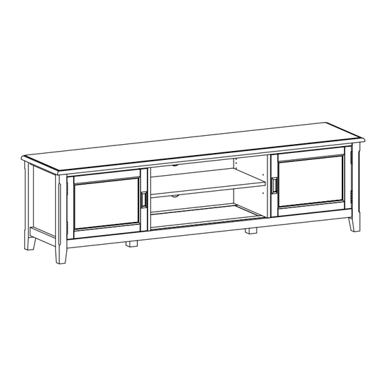
- Page 1 Burlington / Portland / Berkshire 72 inch Low TV Media Stand Model # AXCBURLOW-72-MAH...
- Page 2 Great quality is a right. Thank you for shopping with Simpli Home, America's top brand for high-value furniture. It's time to register your product warranty. It's quick and easy. And you'll be happy you did. ü Activate your 1-year warranty ü...
- Page 3 Review your product and collect rewards! Thank you for your purchase! We hope you enjoy it. We’d love your feedback. Please share a review and get instant rewards! simpli-home.com/product-review Share photos and get your cash back! Send us images or share them on social and qualify for instant rewards.
- Page 4 For Fastest Customer Service: Open your phone’s camera. Point your phone’s camera at the QR code to scan. Click on the pop up. You’ll be taken to our customer service page. Fill the form with your order information and issue. Submit form.
-
Page 5: Safety Information
IMPORTANT : Please read this manual carefully before beginning assembly of this product. Keep this manual for future reference. Safety Information CAUTION: Injuries and damage can occur from furniture tip over if product is not properly anchored to the wall. Use the Furniture Anti-Tipping Restraint provided with the product. -
Page 6: Care And Maintenance
Care & Maintenance This furniture is designed for indoor use. Perhaps the greatest environmental damage to wood furniture comes from wide swings in relative humidity (RH) in our homes. Wood absorbs and desorbs water as relative humidity rises and falls, and in doing so it swells and shrinks. Making matters worse, it expands and contracts unequally along different grain directions. - Page 7 WARNING The maximum diagonal CRT television screen size is 25 inch to 27 inch (63.50 cm to 68.58 cm). For use with televisions weighing 130 lbs or less. Using larger or heavier televisions may cause instability or tip over which can lead to serious injury or even death.
-
Page 8: Maximum Load 25 Lbs
WARNING For use with televisions weighing 130 lbs or less. Use with heavier televisions may result in instability causing tip over resulting in death or serious injury. If a customer wants to use this unit as a TV stand, you must install the TV at position 4 inches from the front edge of console to prevent it from tipping over. - Page 9 Pre-Assembly Information Model # AXCBURLOW-72-MAH Part Description LEFT SIDE RIGHT SIDE QTY 1 QTY 1 QTY 1 RIGHT DIVIDER LEFT DIVIDER BOTTOM SHELF QTY 1 QTY 1 QTY 1 Warning Label SHELF BACK PANEL DOOR QTY 1 QTY 1 QTY 2 BOTTOM SUPPORT LEG QTY 2...
- Page 10 Pre-Assembly Information Model # AXCBURLOW-72-MAH Hardware Description ALLEN KEY SCREW CAM LOCK PIN WOOD DOWEL M6 X 30mm CAM LOCK ALLEN KEY Ø8 X 30mm QTY 18 QTY 6 SETS QTY 1 QTY 6 PHILLIPS SCREW PHILLIPS SCREW ROUND HEAD PHILLIPS SCREW MAGNET AND PLATE M3 X 15mm...
- Page 11 Components - Key Diagram Model # AXCBURLOW-72-MAH...
- Page 12 Assembly Model # AXCBURLOW-72-MAH Step 1 1. Attach three Cam Lock Pins 2 into pre-drilled holes on each Side BL , BR . 2. Use Phillips screwdriver to secure Cam Lock Pins. Do not over-tighten. 3. Insert Dowels 3 into guide holes on parts BL , BR , DL , DR . 4.
- Page 13 Assembly Model # AXCBURLOW-72-MAH Step 2 1. Align Wood Dowels with guide holes on Bottom Shelf C and attach Dividers DL , DR to Bottom Shelf C . 2. Use three Allen Key Screws 1 to attach each Divider DL , DR through guide holes from Bottom Shelf C to pre-drilled holes of Dividers DL , DR .
- Page 14 Assembly Model # AXCBURLOW-72-MAH Step 3 1. Align Cam Lock Pins with guide holes on Bottom Shelf C and attach Sides BL , BR to Bottom Shelf C . 2. Insert six Cam Locks 2 into guide holes on Bottom Shelf C . 3.
- Page 15 Assembly Model # AXCBURLOW-72-MAH Step 4 1. Use three Allen Key Screws 1 to attach each Side BL , BR and Divider DL , DR through guide holes each Side BL ,BR and Divider DL ,DR to pre-drilled holes of Top A . 2.
- Page 16 Assembly Model # AXCBURLOW-72-MAH Step 5 1. Align Bottom Support Leg H with pre-drilled holes on back of Bottom Shelf C . Use Phillips Screwdriver to tighten four Phillips Screws 10 .
- Page 17 Assembly Model # AXCBURLOW-72-MAH Step 6 Warning Label Note: 1. Attach the Back Panel G to back frame using Phillips Screws Round Head 8 through guide holes from Back Panels. 2. Use Phillips Screwdriver to tighten screws. Do not over-tighten.
- Page 18 Assembly Model # AXCBURLOW-72-MAH Step 7 First Step Last Step ( after adjust the door )
- Page 19 Assembly Model # AXCBURLOW-72-MAH Step 8 1. Attach Magnet Plates 5 to bottom corner of Doors F using Phillips Screws 6 into pre-drilled holes on Doors F . 2. Attach Magnets 5 using Phillips Screws 6 into pre-drilled holes Dividers DL , DR . 3.
- Page 20 Assembly Model # AXCBURLOW-72-MAH Step 9 shelf support shelf level 1 anti - tipping shelf level 2 shelf level 3 1. Use four Shelf Supports 9 for Cabinet Shelf E in desired location. 2. Two Shelf Supports 9 may be used on back top of Cabinet Shelf E as a tipping restraint.
- Page 21 Furniture Tip Over Restraint Assembly WARNING Serious or fatal crushing injuries can occur from furniture tip-over. If the furniture tip over restraint kit is not in the box, please contact our customer service department in order to obtain another kit before using the furniture. Step 10 NOTE: The screwdriver is not included in the hardware pack.
- Page 22 Furniture Anti-Tipping Restraint Instructions Attach one of the mounting brackets securely to the back edge of the furniture. Use the shorter screw. Determine where furniture is to be placed and mark location on the wall for mounting bracket screw hole approximately 2 inches below the bracket mounted to the furniture.
Need help?
Do you have a question about the WyndenHall brooklyn + max AXCBURLOW-72-MAH and is the answer not in the manual?
Questions and answers