Advertisement
Advertisement
Table of Contents

Related Manuals for PQWT PQWT-GT Series


Summary of Contents for PQWT PQWT-GT Series
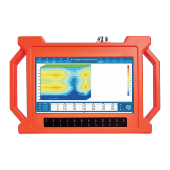
- Page 1 ® PQWT PQWT-GT Series Auto-analysis Geophysical Detector Operation Manual...
- Page 2 PRODUCT DESCRIPTION PRODUCT FEATURES PRODUCT COMPONENTS MAIN PARAMETER DESCRIPTION WIRING METHOD DESCRIPTION MAIN INTERFACE INTRODUCTION MEASUREMENT OPERATION GRAPHICS SWITCHING EXPORT DATA STORAGE OPERATION SYSTEM SETTING OPERATION MULTI-INSTRUMENT WIRING OPERATION BATTERY MANAGEMENT OPERATION PRECAUTIONS AFTER-SALES SERVICE GUIDE...
-
Page 3: Product Description
This series of instruments integrates 5 independent invention patents of PQWT, including data acquisition system, data processing system, automatic mapping system, automatic analysis system and circuit system. It realizes the simultaneous... -
Page 4: Product Components
3.Product Components (1)Accessories (host machine, cable, electrode rod, ch-arger, battery, etc.) ① Host machine: Collect and process data. ② Tool bag: Store tools. ③ Electrode rod: Connect the cable and the ground to be tested. ④ Battery: To supply power to the host. ⑤... - Page 5 4.Main Parameter Description PQ-GT150A PQ-GT300A PQ-GT500A PQ-GT1000A PQ-GT1500A PQ-GT2000A PQ-GT3200A Model No 500m 500m 1000m 150m 500m 500m 1000m 150m Optional depth 150m 1500m 300m 800m 1000m 1500m 300m 2000m 500m 1000m 1500m 2000m 3200m Measuring time 5-6min 6-8min 8-10min 10-15min 15-20min 20-25min...
-
Page 6: Main Interface Introduction
of M1 and N1 is the first measuring point P1, which is the position of the third elec- trode rod. The center point of M2 and N2 is the second measuring point P2, which is the position of the fourth electrode rod, and so on. 6.Main Interface Introduction Line Test: Check the connection status of all electrode rods and ①... -
Page 7: Measurement Operation
Automatic analysis: Analyze abnormal areas. ⑥ ⑦ Export: Export graphics to memory card. File explorer: manage data and connect to a computer. ⑧ ⑨ Settings: adjust screen brightness, select language, view other instru- ment information. ⑩ Zoom: amplify and lessen the graph. Power Display: When fully charged, there are six grids. - Page 8 (2)New measurement Click the measurement parameters in three-frequency or profile mode, and edit the number of line, start point, points, increment and gain .Depth can be selected in section mode.
- Page 9 (3)Increment You can make supplementary measurements on the original measurement line before and after the measurement points. Increment +1 means backward supple- mentary measurement, increment -1 means forward supplementary measure- ment, you can choose between 1-18 measuring points. After setting, you need to place the corresponding cable length and electrode rod number according to the incremental direction and points, and then click collect.
- Page 10 8.Graphics switching After the instrument is collected, the curve graph can be viewed and switched as needed. Click the curve graphs, profile map, 3D renderings display but- tons in the lower right corner to choose to observe different graphics. Click the original picture/processed picture to switch to the corresponding graphic screen.
- Page 11 9.Export Click export button to export current graphics to memory card.
-
Page 12: System Setting Operation
10.Data Storage Operation Connect the host machine and the computer with a dedicated data cable, and click the connect computer button to manage the folders on the computer. 11.System setting operation In the system settings, you can adjust the screen brightness, select the lan- guage, and view other related information of the instrument. - Page 13 12.Multi-Instrument Wiring Operation When measuring on open ground, several auto-analysis geophysical detector can be used for testing. (1)Parallel wiring This method is suitable for situations where the terrain is relatively open and flat, and there is no obvious valley reference and judgment on the ground, and the direction of the underground structure cannot be judged intuitively.
- Page 14 (2)Cross wiring one It is suitable for situations where underground faults or fissures generally develop along the direction of valley extension. Cross-wiring method can be used, diago- nal through the valley wiring, lateral intercept construction as soon as possible.
- Page 15 (3)Cross wiring two Same as cross wiring one. 13.Battery Management Operation When placing the battery, place the positive and negative poles of the battery and the positive and negative poles of the battery box correspondingly.
- Page 16 14.Precautions (1)Pay attention to the correct operation method when using the instrument. The correct use will prolong the life of the instrument. (2)The instrument is not waterproof, please do not immerse the instrument in water or operate it in rain. (3)Do not knock the LCD hard, do not expose the LCD to direct sunlight for a long time, if there is a touch failure, please shut down and restart it.
- Page 17 (3)After-sales service process 1)Please contact the relevant sales staff to confirm the problem. 2)If the instrument needs to be returned to the factory for maintenance, the user shall bear the delivery cost. When sending the instrument back to the factory, please specify: purchase time, fault conditions, return address, contact name, contact number and the salesperson, and send back the warranty card together.
Need help?
Do you have a question about the PQWT-GT Series and is the answer not in the manual?
Questions and answers
Please provide a depth-frequency table for GT500 instrument
@Mike Ndongo frequencies 1-56
Did we survey on a wet surface of land