Table of Contents
Advertisement
Quick Links
Advertisement
Table of Contents

Subscribe to Our Youtube Channel
Related Manuals for Premier PHPM300 Series

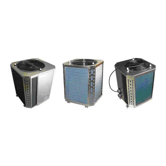
Summary of Contents for Premier PHPM300 Series
- Page 1 Installation and Operation Manual MODEL: PHPM300 – PHPM800 series Ver.0811 - 12...
- Page 2 Congratulations on the purchase of your Premier Heat Pumps swimming pool / Spa pool hot water heat pump. Our Heat Pumps are manufactured to the highest standards and quality, designed for New Zealand conditions. Our heat pumps incorporate high quality compressors, stainless steel cases, Digital controllers and Titanium heat exchangers.
-
Page 3: Table Of Contents
Contents 1~ Operating Principle and technical description ……………………… 2 2~ Features and characteristics ………………………………………………………………… 3 3~ Technical data ……………………………………………………………………………………………… 4~ Electric circuit diagram …………………………………………………………………… 5~ Operational instructions …………………………………………………………………………… 6 6~ Instructions and notices for installation ……………………… 13 7~ Safety Cautions ……………………………………………………………………………………………... -
Page 4: Operating Principle And Technical Description
1. 1, Technical Description The swimming pool heat pump water heater basically comprises a compressor, an evaporator, capillary or expanding valves and a condenser. 1.2, Working principle Heat pumps use electricity to capture heat and move it from one place to another. They don’t generate heat. -
Page 5: Features And Characteristics
2. Features and Characteristics 2.1, Efficient and economical This unit’s Coefficient of Performance (cop) is 4.0 -5.0. In comparison, an electric boilers (cop) is 0. 95, a gas or oil boiler (cop) is about 0. 5 - 0. 8, a coal-boiler (cop) is only about 0.3-0.7. This means high efficiency, energy performance and savings. -
Page 6: Technical Data
3, Technical Data Data Main Technical Data Heating Rated Stated Power Noise Water In\Out Model Capacity Power Current Input Level Flow Pipe Dimension (Btu) [dB(A)] Size (W) (A) (mm) (V/PH/Hz) (aprox) (mm) 49400 2770 11.7 240/1/50 ≥6.5 575*575*750 PHPM600 14.70 kw 64000 3600 17.0... -
Page 7: Electric Circuit Diagram
4. Electrical circuit diagram 4.1, Ventilation and defrosting CIRCUIT DIAGRAM BLUE BLUE BLUE CONTACTOR BLACK BLACK NO.1 11 12 FUSIBLE THE RMOSTAT 11 12 FAN CAPACITOR RUNNING CAPACITOR POWER COMP Page 5... -
Page 8: Operational Instructions
5. OPERATIONAL INSTRUCTIONS 5.1 Panel: Panel and Functional description. Index Light Name Light Flash In the state of temp Temp Setting setting Ready to refrigerate, in the state of compressor start delay Refrigeration Refrigerating protection Ready to heat, in the state of compressor start delay Heat Heating protection... - Page 9 5.2 The controller LED display The LED Panel shows the pool temperature, if the display shows ―SHr‖ or ―OPE‖ then there is a water temperature sensor failure. The temperature and the alarm code (Axx) will show alternately when there is an alarm state. The fault codes are shown below: Code Signification...
- Page 10 5.4 How to read the outdoor temperature When displaying current temperature, press ―↓‖ key, Controller will display defrosting temperature. Release the ―↓‖ key, then return to current temperature. Notice that if you press the key and hold it for 5 seconds, the controller will enter or exit the defrosting state forcibly. 5.5 How to check and adjust the real clock time Press the key ―Set‖...
- Page 11 5.8 Internal parameter code is shown below Factory Sort Code Parameter Name Range Unit Remark setting The setting range is limited by F13 F11 Setting temperature F14 – F13 ℃/℉ and F14 Control the temperature difference, F12 Temperature difference 0.1 – 20 ℃/℉...
- Page 12 00:00— F64 Period 2 end time 18:00 23:59 00:00— F65 Period 3 start time 22:00 23:59 00:00— F66 Period 3 end time 00:00 23:59 0:Automatic F69 Run Mode 1:Economical OFF means no password F80 Password 0001 -- 9999 0000 means clearing password C: Centigrade F81 Temperature unit F: Fahrenheit...
- Page 13 the controller begins to heat when the temperature of the temperature sensor is under ―setting temperature - temperature difference‖, and it stops heating when the temperature is over ―setting temperature + temperature difference‖. 5.11 Compressor delay time The compressor delay time is set by F21, for example, 3 minutes. The controller contains a― compressor stop calculagraph‖, and it begins to time when compressor stops, the program first checks the calculagraph before starting the compressor next time, the program will immediately start the compressor if the calculagraph reachs 3 minutes ,if the calculagraph doesn’t reach 3 minutes ,it will start...
- Page 14 The Compressor and fan stop running when defrost starts, and the valve is enabled after 30 seconds, then after 5 seconds, compressor starts running and fan does not start. Compressor stops running after defrost stops, and valve is disable after 30 seconds, then after 5 seconds, compressor and fan start running.
-
Page 15: Instructions And Notices For Installation
5.16 Password In order to prevent unauthorized persons from changing the parameters, you can set a password (F80), and if you have set a password, the controller will ―hint‖ you to enter the password after you press the key ―M‖ for 5 seconds, you must enter the correct password, and then you can set / modify the parameters. If you don’t require the password, you can set F80 to ―OFF‖. - Page 16 6.2 The requirements for heat pumps include the following 1, Appropriate site location and clearances; 2, sufficient air ventilation; 3, Proper electrical wiring; 4, Adequate water flow; NOTE: This manual provides the information needed to meet the above requirements. Review all applicable and installation procedures completely before continuing the installation 6.3 Clearances Avoid placing the heat pump in locations where it can cause damage by water or condensate leakage.
- Page 17 6.4 Equipment Location Pad Place the heat pump on a flat surface, such as a concrete or fabricated slab (pad).This allows proper drainage of condensation and rain water from the base of the unit. If’ possible, the pad should be placed at the same level or slightly higher than the filter system equipment pad.
- Page 18 the base of the heat pump is fitted with a 19mm diameter barbed adapter and route it to dispose of the condensate into a drain or outside of the building. NOTE: It is important to remember that no part of the tubing or hose may be above the level of the drain hole in the base of the heat pump.
- Page 19 Page 17...
- Page 20 6.9 Multiple Heat Pump Connections All Plumbing on multiple heat pump units must be done in parallel (see fig. 2 and fig.3)) Figure 2 An equal flow of water to each heat pump is important for optimum operation. Page 18...
- Page 21 Page 19...
-
Page 22: Safety Cautions
6. 10 Instructions and information for installation NOTE: The pad on which the unit is installed must be sturdy and able to withstand its weight. If not, it is possible that the unit may fall off and be destroyed. NOTE: The electrical system and installation must comply with the local regulations and rating data in the technical sheet. -
Page 23: Troubleshooting And Solutions
Please regularly clean the evaporator by professional means. If the unit has worked for a long time, there could be more dust in the evaporator coil, and the airflow volume will decrease. DO NOT use high pressure water cleaning system or water blaster. To maintain efficiency, do not set the temperature too high or too low. -
Page 24: Notice To Installer
NOTICE TO INSTALLER + Install the Heat Pump on the water return side of the pool water pump, after the filtration system and prior to any chemical dispensing unit. It is recommended that a one way valve be installed to prevent any potential back flow of chemical into the Heat Pump when the pool water pump is switched off.
Need help?
Do you have a question about the PHPM300 Series and is the answer not in the manual?
Questions and answers