Table of Contents
Advertisement
Quick Links
EN
2
TOREX S.p.A.
Via Rodolfo Ferrari 8-10
I-41030 S. Prospero s/S
(MO) - Italy
ILT
BIN LEVEL INDICATORS
ASSEMBLY AND
MAIN INSTRUCTIONS
FOR USE AND
MAINTENANCE
Manual No. TOR.ILT.--.M.A1.1022.EN
Latest update: October 2022
ORIGINAL INSTRUCTIONS IN ENGLISH
Issue: A1
+ 39 / 059 / 8080811
fax
+ 39 / 059 / 908204
e-mail
torex@torex.it
internet
www.torex.it
Advertisement
Table of Contents

Related Manuals for WAMGROUP Torex ILTA Series

Summary of Contents for WAMGROUP Torex ILTA Series
- Page 1 BIN LEVEL INDICATORS ASSEMBLY AND MAIN INSTRUCTIONS FOR USE AND MAINTENANCE Manual No. TOR.ILT.--.M.A1.1022.EN Issue: A1 Latest update: October 2022 ORIGINAL INSTRUCTIONS IN ENGLISH TOREX S.p.A. + 39 / 059 / 8080811 Via Rodolfo Ferrari 8-10 + 39 / 059 / 908204 I-41030 S.
- Page 2 All the products described in this catalogue are manufactured according to TOREX S.p.A. Quality System procedures. The Company’s Quality System, certified according to ISO 9001-2015 guarantees that the entire production process, from the customer’s order to the after sales service, can fulfil the product quality standard. This publication cancels and replaces any previous edition and revision.
-
Page 3: Table Of Contents
10.22 INDEX TOR.ILT.--.M.A1.1022.EN Issue: A1 TABLE OF CONTENTS 1.0 GENERAL INFORMATION ........................1 1.1 Scope of the Manual .........................1 1.2 Symbols ............................2 1.3 Glossary and terminology .........................3 1.4 Manufacturer’s data and identification of device ................4 1.5 Request for assistance ........................5 1.6 Warranty ............................5 1.7 Exclusion of responsibility .........................5 2.0 INFORMATION REGARDING SAFETY ....................6 2.1 General safety prescriptions ......................6... - Page 4 10.22 INDEX TOR.ILT.--.M.A1.1022.EN Issue: A1 6.0 INFORMATION REGARDING USE .......................25 6.1 Start-up ............................25 6.2 Machine shut-down at the end of the work cycle ................25 6.3 Long shut-downs of the device .......................26 7.0 INFORMATION REGARDING MAINTENANCE ..................27 7.1 Removing the material residues ......................27 8.0 REPLACEMENT OF PARTS ........................28 8.1 Safety recommendations for replacement ..................28 8.2 Returning the device ........................28...
-
Page 5: General Information
10.22 1.0 GENERAL INFORMATION TOR.ILT.--.M.A1.1022.EN Issue: A1 1.1 Scope of the Manual This Manual has been prepared by the Manufacturer to provide the operating technical information for instal- lation, operation and maintenance of the device concerned. The Manual, which is an integral part of the device concerned, must be preserved throughout the life of the device in a known easily accessible place, available for consultation whenever required. -
Page 6: Symbols
10.22 1.0 GENERAL INFORMATION TOR.ILT.--.M.A1.1022.EN Issue: A1 1.2 Symbols To highlight certain parts of the text, for purposes of safety, or to indicate important information, certain symbols are used, the meaning of which is described below. It is important to comply with and scrupulously follow the information highlighted by the symbols. Danger - Warning Indicates situations of serious danger which, if ignored, can be risky for the health and safety of per- sons. -
Page 7: Glossary And Terminology
10.22 1.0 GENERAL INFORMATION TOR.ILT.--.M.A1.1022.EN Issue: A1 1.3 Glossary and terminology Operator: person appropriately trained and authorized by the Production Manager for setting up the device concerned and carrying out routine maintenance. Installer: organization with specialized technicians and appropriate equipment for carrying out risk-free instal- lation and extraordinary maintenance. -
Page 8: Manufacturer's Data And Identification Of Device
Manufacturer and ask for a new ID plate and replace it. The ID plates shown identify the equipment concerned and its main components. The plates show the reference necessary for operating safety. TOREX SpA WAMGROUP Via Rodolfo Ferrari 8-10 41030 S.Prospero (MO) ITALY +39/0598080811... -
Page 9: Request For Assistance
10.22 1.0 GENERAL INFORMATION TOR.ILT.--.M.A1.1022.EN Issue: A1 1.5 Request for assistance For all technical assistance, contact the Manufacturer’s service network. For all requests, provide the device identification data, the type of problem encountered and all other informa- tion which could be useful for identifying the problem. 1.6 Warranty The conditions for validity and applicability of the warranty are specified in the sales contract. -
Page 10: Information Regarding Safety
10.22 2.0 INFORMATION REGARDING SAFETY TOR.ILT.--.M.A1.1022.EN Issue: A1 2.1 General safety prescriptions Read the Instruction Manual carefully and strictly follow the instructions it includes, especially those regarding safety. Most accidents at the workplace are caused by negligence, failure to follow the most elementary safety regulations and incorrect or improper use of tools and equipment. -
Page 11: Safety Prescriptions For Installation
10.22 2.0 INFORMATION REGARDING SAFETY TOR.ILT.--.M.A1.1022.EN Issue: A1 2.3 Safety prescriptions for installation Before starting with installation, a “Safety Plan” must be implemented to safeguard the personnel di- rectly involved and those who carry out operations in the surrounding area. All the laws must be strictly applied, especially those concerning workplace safety. -
Page 12: Safety Prescriptions For Maintenance And Replacement Of Components
10.22 2.0 INFORMATION REGARDING SAFETY TOR.ILT.--.M.A1.1022.EN Issue: A1 2.5 Safety prescriptions for maintenance and replacement of components Danger - Warning Before carrying out any operation on the device concerned, ensure it is switched off and disconnected from all mains and use suitable devices to prevent the possibility of the power sources being activated accidentally. -
Page 13: Technical Information
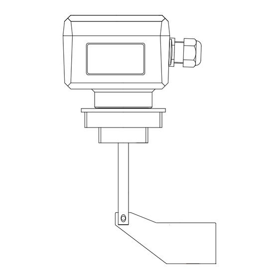
10.22 3.0 TECHNICAL INFORMATION TOR.ILT.--.M.A1.1022.EN Issue: A1 3.1 General description of device The ILT level indicator has been designed to signal the level of material inside silos, hoppers and bins, through its rotary movement. 3.2 Main components Item DESCRIPTION COVER BODY CONNECTING BUSH PADDLE... -
Page 14: Operating Principle
10.22 3.0 TECHNICAL INFORMATION TOR.ILT.--.M.A1.1022.EN Issue: A1 3.2 Versions - Order code Connection Connection 1 ½“ - 2 ½“ 1 ¼“ NPT cylindrical 1 ¼“ NPT cylindrical 24/48 VAC - 50/60 Hz 115/230 VAC - 50/60 Hz Power supply Power supply 24 VDC 12 VDC 22..30 VDC - 22..250 VAC with sensor... -
Page 15: Technical Data And Specifications
10.22 3.0 TECHNICAL INFORMATION TOR.ILT.--.M.A1.1022.EN Issue: A1 3.6 Technical data and specifications MECHANICAL FEATURES ILTA_, ILTC_ , ILTD_, ILTE_ ILTR_ Protection IP 65 Standard connections 1 1/2” + 2 1/2” ISO 228 , 1 1/4" NPT Connection bushing material Plastic or aluminium Shaft and paddle material Stainless steel Signal delay... - Page 16 10.22 3.0 TECHNICAL INFORMATION TOR.ILT.--.M.A1.1022.EN Issue: A1 3.6.1 Version for high temperatures processing Operation temp. Code Power supply Code Power supply Operation temp. ILT021AA1AA 150°C 24 VDC / 22..230 VAC 50-60 Hz ILT031AA1AA 250°C Different power supply values available upon request.; Different power supply values available upon request 1 1/2"...
-
Page 17: Environmental Operating Limits
10.22 3.0 TECHNICAL INFORMATION TOR.ILT.--.M.A1.1022.EN Issue: A1 3.7 Environmental operating limits OPERATION CONDITIONS -20°C..+60°C Pa=0.8..1.1 bar Maximum impact energy Maximum impact energy value on the connecting value on the connecting Pa-0.1..Pa+0.8 bar bush bush -20°C..+80°C -20°C..+80°C ρ = 0.3..2 t / m³ max.15 Nm max.2kN max. -
Page 18: Overall Dimensions
10.22 3.0 TECHNICAL INFORMATION TOR.ILT.--.M.A1.1022.EN Issue: A1 3.8 Overall dimensions M20x1.5 M20x1.5 2 1/2" ISO 228 1 1/2" ISO 228 Ø10 90.5... -
Page 19: Safety And Information Signs
10.22 3.0 TECHNICAL INFORMATION TOR.ILT.--.M.A1.1022.EN Issue: A1 3.9 Safety and information signs Danger - Warning Follow the signs on the plates. Ensure the plates are legible; otherwise clean them and replace the damaged ones, applying them in their original position. -
Page 20: Information Regarding Handling And Transport
10.22 4.0 INFORMATION REGARDING HANDLING AND TRANSPORT TOR.ILT.--.M.A1.1022.EN Issue: A1 4.1 Type of packaging Danger - Warning The person authorized for unloading must implement all necessary measures to ensure their own safety and the safety of others. Use personal protection devices and means / accessories (ropes, hooks, shackles etc.) suitable for the load to be handled. -
Page 21: Reception Of Goods
10.22 4.0 INFORMATION REGARDING HANDLING AND TRANSPORT TOR.ILT.--.M.A1.1022.EN Issue: A1 4.2 Reception of goods On receiving the goods, check if type and quantity match the data on the acknowledgement of order. Possible damage has to be immediately communicated in writing in the space provided to this purpose in the waybill. -
Page 22: Installation And Fixing
10.22 5.0 INSTALLATION AND FIXING TOR.ILT.--.M.A1.1022.EN Issue: A1 5.1 Safety prescriptions for installation Danger - Warning The replacement operations must be carried out by a specialist authorized technician with specific skills. Provide appropriate safety measures and use suitable equipment to prevent risk of work accident to persons involved in the operations and to those nearby. - Page 23 10.22 5.0 INSTALLATION AND FIXING TOR.ILT.--.M.A1.1022.EN Issue: A1 Weld Weld Drill Drill Screw in Screw in Cable gland toward Cable gland toward bottom side bottom side...
-
Page 24: Electrical Connections
Important The connection must be made in accordance with the voltage value shown on the rating plate and in accordance with applicable standards. TOREX SpA WAMGROUP 24 (ILTD_) Via Rodolfo Ferrari 8-10 41030 S.Prospero (MO) ITALY 12 (ILTE_) - Page 25 10.22 5.0 INSTALLATION AND FIXING TOR.ILT.--.M.A1.1022.EN Issue: A1 TOREX SpA FSL / FSH WAMGROUP Via Rodolfo Ferrari 8-10 41030 S.Prospero (MO) ITALY 12VAC +39/0598080811 Year: 2022 LEVEL INDICATOR ILTR0 TYPE: Voltage: 22..30 V 22..250 V 50/60 Hz Power: Encl: IP65 max.250V- 2A...
- Page 26 10.22 5.0 INSTALLATION AND FIXING TOR.ILT.--.M.A1.1022.EN Issue: A1 5.3.2 ILTR versions signals logics The ILTR version features an additional signal for sensor failure indication. In normal operating conditions the contact 5-8 is closed. In the event of a power failure or malfunction of the level indicator, the contact 5-8 opens. The following figure shows the switching logic of signal contact, which can apply two different operation modes (FSH / FSL), to be set through the jumper fitted on the electronic module.
- Page 27 10.22 5.0 INSTALLATION AND FIXING TOR.ILT.--.M.A1.1022.EN Issue: A1 5.3.3 Safety instructions on the electrical connections - provide protection for the output relay contacts against voltage peaks due to inductive voltages. - make sure the wires surface exposed does not exceed 8 mm length (hazard of contact with powered parts). - position a power switch near the device.
-
Page 28: Adjustments
10.22 5.0 INSTALLATION AND FIXING TOR.ILT.--.M.A1.1022.EN Issue: A1 5.4 Adjustments The sensor features an spring adjustable in 3 positions meant to change sensitivity of the indicator. Move the spring hook using a small pliers. grezzo coarse medio average molla spring fine fine 5.4.1 Specific settings for ILTR... -
Page 29: Information Regarding Use
10.22 6.0 INFORMATION REGARDING USE TOR.ILT.--.M.A1.1022.EN Issue: A1 6.1 Start-up Pericolo - Attenzione Before starting up the device, the operator in charge has to ensure all safety devices are enabled and that the operation conditions are met. Before carrying out any intervention on device, check to make sure it has been set in safety conditions. Before the definitive starting of the device valve, ensure the installation has been completely and properly car- ried out and that connections to external mains were made according to the following indications: 1) Read fully the INSTALLATION, USE AND MAINTENANCE manual. -
Page 30: Long Shut-Downs Of The Device
10.22 6.0 INFORMATION REGARDING USE TOR.ILT.--.M.A1.1022.EN Issue: A1 6.3 Long shut-downs of the device 6.3.1 STORAGE PRIOR TO INSTALLATION - Storage conditions below -15°C are forbidden - Avoid as much as possible salty and moist environments. - Place the device indoors on wooden platforms, protected from atmospheric agents. - The device must not be stored in the open or in areas where vapours or substances incompatible with its construction materials (even slightly corrosive substances) are present. -
Page 31: Information Regarding Maintenance
10.22 7.0 INFORMATION REGARDING MAINTENANCE TOR.ILT.--.M.A1.1022.EN Issue: A1 Danger - Warning Before carrying out any maintenance activity, activate all the safety devices to ensure the safety of the persons involved in the operations and those nearby. Set the device concerned in safety condition. Wear suitable personal protection equipment;... -
Page 32: Replacement Of Parts
10.22 8.0 REPLACEMENT OF PARTS TOR.ILT.--.M.A1.1022.EN Issue: A1 8.1 Safety recommendations for replacement Danger - Warning The replacement operations must be carried out by an authorized specialized technician with specific skills in the sector concerned (mechanical, electrical etc.). Provide appropriate safety measures and use suitable equipment to prevent risk of work accident to persons involved in the operations and to those nearby. -
Page 33: Information Regarding Faults
10.22 9.0 INFORMATION REGARDING FAULTS TOR.ILT.--.M.A1.1022.EN Issue: A1 9.1 Trouble-shooting Minor problems can be solved without consulting a specialist. The following Table contains a list of the most common problems, the possible causes and possible remedies. For particularly difficult actions which are not mentioned in the Table, contact the Manufacturer’s Customer Service Department. -
Page 34: Check-List In Case Of Fault
10.22 9.0 INFORMATION REGARDING FAULTS TOR.ILT.--.M.A1.1022.EN Issue: A1 PROBLEM SOLUTION Adjustments on trimmers / jumpers have no effect on the The power supply must be disconnected and operation of the level sensor reconnected. (ILTR) Check that the supply voltage is not below the prescribed limit. -
Page 35: Aattachments
10.22 A ATTACHMENTS TOR.ILT.--.M.A1.1022.EN Issue: A1 A1 Spare parts and accessories ACCESSORIES Sleeve 1+1/2” 4538020100 Sleeve 2+1/2” 4538020150 Double paddle kit 13N07052A (Item 3) Green lamp cover M20x1.5 3848004510 (Item 5) Red lamp cover M20x1.5 3848004530 (Item 5) 24 volt lamp 3848004050 (Item 6) 48 volt lamp 3848004055 (Item 6)
Need help?
Do you have a question about the Torex ILTA Series and is the answer not in the manual?
Questions and answers