
Related Manuals for emmeti Evo


Summary of Contents for emmeti Evo
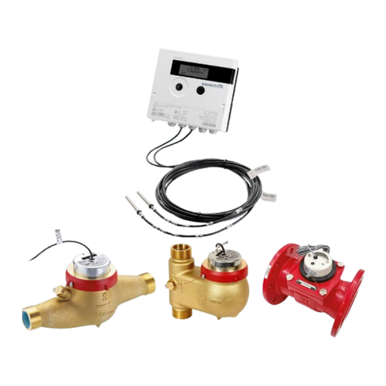
- Page 1 Installation and user manual Riscal./raffred. Heating and Heat /Cool Cooling Misuratore energia alte portate | Febbraio 2023 High capacity energy meter | February 2023...
- Page 2 IT IT pagina3 page 33 Vi ringraziamo per la fiducia concessaci nell’acquisto Thank you for your choice of this measuring device. del misuratore di energia. Carefully read this manual which contains the specifi- Vi invitiamo a leggere attentamente questo manuale cations and all useful information for correct operation dove sono riportate le caratteristiche tecniche e tutte of the high flow rate measuring device.
-
Page 3: Table Of Contents
Indice 1. Contenuto della confezione ......................3 2. Introduzione ............................3 3. Contatore volumetrico per acqua ....................4 4. Unità elettronica e sensori di temperatura ..................9 5. Codici di errore ..........................22 6. Interfaccia M-Bus ..........................24 7. Configurazione con testina ottica ....................24 8. Abbinamento coni concentratori .......................25 9. -
Page 4: Contatore Volumetrico Per Acqua
3. Contatore volumetrico per acqua 3.1 Contatori per acqua con attacco filettato installazione orizzontale 3.1.1 Caratteristiche - Contatore a getto multiplo super-dry a trasmissione magnetica; - Certificato secondo la Direttiva 2014/32/EU MID (MI-004); - Classe ambientale B, classe di accuratezza 3 (EN 1434); - Cassa in ottone;... - Page 5 3.2 Contatori per acqua con attacco filettato installazione verticale 3.2.1 Caratteristiche - Calotta metallica di protezione; - Contatore a getto multiplo super-dry a trasmissione magnetica; - Totalizzatore ruotabile; - Filtro in ingresso; - Certificato secondo la Direttiva 2014/32/UE MID (MI-004); - Materiali ad alta resistenza all’usura e alla corrsione;...
- Page 6 3.2.3 Perdite di carico contatori per acqua con attacco filettato installazione orizzontale e verticale. 1000 DN25 Kv=10 DN32 Kv=13 DN40 Kv=21 1000 10000 Q [ /h] 3.2.4 Installazione contatore per acqua con attacco filettato installazione orizzontale e verticale. Posizionare il contatore nel punto più basso dell’impianto in modo tale da evitare accumuli d’aria, rispettando la direzione del flusso indicata sul corpo del contatore.
- Page 7 3.3.2 Dati tecnici dimensionali Misura Portata nominale q Portata minima q Portata massima qs Pressione di esercizio PN Temperatura max di esercizio °C Valore impulsi l/imp 1000 10,6 13,3 15,6 18,1 40,1 Peso...
- Page 8 3.3.3 Perdite di carico misuratore di energia flangiato DN50 - Kv=79 DN65 - Kv=126 DN80 - Kv=199 DN100 - Kv=316 DN125 - Kv=506 DN150 - Kv=791 1000 1000 10000 100000 1000000 Q [l/h] 3.3.4 Installazione Posizionare il contatore nel punto più basso dell’impianto in modo tale da evitare accumuli d’aria, rispettando la direzione del flusso indicata sul corpo del contatore.
-
Page 9: Unità Elettronica E Sensori Di Temperatura
4. Unità elettronica e sensori di temperatura 4.1 Dati unità elettronica e sensori di temperatura Unità elettronica Temperatura di immagazzinaggio °C -25 ÷ 55 Temperatura ambiente di utilizzo °C 5÷55 Differenza di temperatura in caldo 3÷100 Differenza di temperatura in freddo -3 ÷... - Page 10 Sensori di temperatura Resistenza di precisione in platino Pt500; versione separata conforme allo standard EN 60751 Lunghezza cavi collegamento 3 m (2 conduttori per ogni sonda) Diretta, per contatori volumetrici fino alla misura DN25 Installazione In pozzetti, conforme alla EN 1434, per misure superiori a DN25 Tutte le classi si riferiscono alle direttive vigenti relative ai misuratori di energia.
- Page 11 4.4 Collegamento dei componenti ATTENZIONE ! Installare prima le sonde di temperatura, e quindi collegare il contatore volumetrico all’unità elettronica; in questo modo si evita la comparsa di messaggi di errore non previsti. In fase iniziale lo strumento mostrerà sul display un codice di errore “ERR 03”, che scomparirà una volta installate le sonde di temperatura (prima rilevazione delle temperature).
- Page 12 4.4.2 Collegamento del contatore volumetrico - Collegare l’uscita ad impulsi del misuratore volumetrico all’unità elettronica sfruttando gli appositi pressacavi. - Fissare i cavi alla morsettiera, come da figura seguente. - Verificare che i cavi siano collegati saldamente. 4.4.3 Collegamento interfaccia M-Bus È...
- Page 13 E’ possibile collegare fino a 3 contatori volumetrici con uscita impulsiva utilizzando il modulo 3 ingressi impulsivi per misuratore EVO opzionale. Il modulo prevede un cavo a 6 fili. L’estremità con il connettore a 6 pin deve essere collegata allo slot B presente sulla parte in basso a sinistra della scheda.
- Page 14 4.5 Installazione dei sensori di temperatura - Utilizzare sempre la stessa tipologia di installazione delle sonde nei flussi di mandata e di ritorno (i sigilli delle sonde non devono essere rimossi). - Installare il pozzetto in posizione obliqua o perpendicolare rispetto al flusso a seconda del diametro della tubazio- ne, in maniera tale che la punta della sonda arrivi almeno al centro della tubazione.
- Page 15 1-03 Valori di lettura alla fine dell’anno precedente. Visualizzazioni alter- nate nel seguente ordine: 1-03-01: data (fine anno precedente) 1-03-02: valore totale delle calorie 1-03-03: valore totale delle frigorie 1-03-04: volume totale 1-03-05: valore del registro tariffa 1 1-03-06: valore del registro tariffa 2 1-03-07: valore relativo all’ingresso impulsivo 1 1-03-08: valore relativo all’ingresso impulsivo 2 1-03-09: valore relativo all’ingresso impulsivo 3...
- Page 16 1-04 Volume totale in m 1-05 Data corrente alternata all’ora 1-06 Codice di errore. Visualizzazioni alternate in forma binaria ed esadecimale. 1-07 Registro tariffa 1: valore alternato al numero di registro tariffa. 1-08 Registro tariffa 2: valore alternato al numero di registro tariffa. 1-09 Lettura istantanea del contalitri collegato all’ingresso impulsivo 1, alternata al valore degli impulsi (1 impulso ogni 10 litri).
- Page 17 1-10 Lettura istantanea del contalitri collegato all’ingresso impulsivo 2, alternata al valore degli impulsi (1 impulso ogni 10 litri). 1-11 Lettura istantanea del contalitri collegato all’ingresso impulsivo 3, alternata al valore degli impulsi (1 impulso ogni 10 litri). 4.6.2 Livello tecnico 2-01 Potenza istantanea in kW.
- Page 18 2-06 Prima della messa in servizio: giorni dalla data di fabbricazione Dopo la messa in servizio: giorni di funzionamento alternati con i giorni di funzionamento dopo aver totalizzato un valore dell’energia > 10 kWh. 2-07 Indirizzo Primario M-Bus. 2-08 Indirizzo secondario (numero di matricola). 2-09 Versione firmware...
- Page 19 4.6.3 Livelli statistici 3-01 ... 3-30 Lettura dei consumi nei 15 mesi precedenti alternata con la relativa data (metà e fine mese, valori quindicinali). Visualizzazioni alternate nel seguente ordine per ogni data: 3-01-01:data a cui fanno riferimento i valori 3-01-02: valore totale delle calorie 3-01-03: valore totale delle frigorie 3-01-04: volume totale 3-01-05: valore del registro tariffa 1...
- Page 20 4-02 Portata massima in m /h alternata alla data ed all’ora. 4-03 Tempratura massima di mandata in °C alternata alla data ed all’ora. 4-04 Temperatura massima di ritorno in °C alternata alla data ed all’ora. 4-05 Differenza massima di temperatura in K alternata alla data ed all’ora.
- Page 21 4.6.5 Livello visualizzazione configurazione 5-01 Visualizzazione configurazione dell’unità di misura dell’energia. Nota: La configurazione deve essere effettuata da personale tecni- co qualificato tramite il software Device Monitor fornito in dotazione con la testina ottica insime al relativo manuale. 5-02 Visualizzazione configurazione del punto di installazione. Nota: La configurazione deve essere effettuata da personale tecni- co qualificato tramite il software Device Monitor fornito in dotazione con la terstina ottica insime al relativo manuale.
-
Page 22: Codici Di Errore
5. Codici di errore Quando lo strumento rileva un errore, questo è il simbolo che viene visualizzato sul display. Inoltre viene visualizzato un numero di errore in formato esadecimale alternato con la schermata principale (energia totale, 1-01). L’errore può essere visualizzato anche nel menù alla posizione 6 del primo livello: mes- saggio in formato binario (1-06-01) alternato al messaggio in formato esadecimale (1-06-02). - Page 23 Gli errori, a volte, possono comparire anche congiuntamente, in questo caso si consiglia di considerare il messaggio in formato binario (livello 1-06-1) e sfruttare la tabella sotto per fare la diagnosi e identificare quali errori sono presenti: Errore Esempio: rottura cavo sonda di tempera- tura di mandata e rottura cavo sonda di temperatura di ritorno.
-
Page 24: Interfaccia M-Bus
- fattore di conversione litri/impulso dei 3 ingressi impulsivi se sono collegati i contatori volumetrici (i conta- tori volumetrici Emmeti utilizzano un fattore di conversione litri/impulso pari a 10/1); - valori iniziali dei 3 ingressi impulsivi (devono coincidere con i valori visualizzati sui contatori volumetrici nel momento in cui questi vengono collegati al misuratore di energia). -
Page 25: Abbinamento Coni Concentratori
Ogni strumento genera una riga all'interno della quale vengono popolate le celle di interesse in riferimento alle colonne descritte. Di default, per ogni misuratore di energia EVO caldo/freddo con 3 ingressi impulsivi, viene generata una riga all'interno della quale sono popolate solo le celle con i valori di interesse con le relative unità... - Page 26 8.2 Concentratore M-Bus Relay per 3-20-60 dispositivi: lettura con software FSERVICE In seguito ad una lettura del misuratore di energia effettuata dal concentratore M-Bus, il software FService genera una tabella composta da 30 righe. La prima e la seconda colonna indicano la data e l’ora della lettura effettuata dal concentratore, la terza colonna indica l’indirizzo primario, la quarta il numero di matricola (indirizzo M-Bus secondario), la quinta un riferimento di produzione, la terzultima un riferimento allo strumento (0=misuratore di energia;...
- Page 27 Data Ora Indir. Prim Fabb N° Valore Unità Descrizione Tipo Tariffa Posiz. Tariffa 13.09.17 11.45 72550304 MAD 20 energy instant. 13.09.17 11.45 72550304 MAD 21 energy instant. 13.09.17 11.45 72550304 MAD 22 energy instant. 13.09.17 11.45 72550304 MAD 23 energy instant.
- Page 28 1) Numero di matricola. 2) Energia totale (calorie) consumata dall’installazione all’istante di tempo riportato nelle prime 2 colonne della tabella. 3) Volume totale rilevato dal misuratore di energia dall’installazione all’istante di tempo riportato nelle prime 2 colonne della tabella. 4) Potenza rilevata dal misuratore di energia nell’istante di tempo riportato nelle prime 2 colonne della tabella. 5) Potenza massima rilevata dal misuratore di energia dall’...
- Page 29 071101 (report semplificato): con questo tipo di report, per ogni lettura di un misuratore di energia EVO caldo/freddo DN15 o DN20 con 3 ingressi impulsivi, viene generata una riga con 10 valori (i riferimenti di seguito sono relativi alle colonne del file CSV): A: numero di serie del concentratore.
- Page 30 A: numero di serie del concentratore. X: Valore registro/tariffa 1 dall’installazione al momento B : indirizzo secondario (numero di matricola) del misuratore della lettura fatta dal concentratore. di energia. Y: Valore registro/tariffa 1 dall’installazione al momento C: data e ora della lettura fatta dal concentratore. della lettura effettuata dal misuratore di energia.
-
Page 31: Dichiarazione Di Conformita' Mid
9. Dichiarazione di conformita’ MID In relazione ai misuratori di energia descritti in questo manuale, il costruttore conferma che lo strumento è conforme ai requisiti della Direttiva 2014/32/EU MID del 26 febbraio 2014 relativa agli strumenti di misura, in particolare all’allegato MI-004, alla Direttiva 2014/30/EU sulla compatibilità elettromagnetica, alla Direttiva 2014/30/EU relativa alla compatibilità... -
Page 33: Contents Of The Package
Contents 1. Contents of the package ......................... 33 2. Introduction ............................33 3. Volumetric water meter ........................34 4. Temperature sensors and electronic unit .................. 39 5. Error code ............................52 6. Interface M-BUS ..........................54 7. Configuration of the energy meter ....................54 8. -
Page 34: Volumetric Water Meter
3. Volumetric meter for water 3.1 Water meters with threaded connection horizontal installation 3.1.1 Characteristics - Super-dry multiple jet meter with magnetic transmission; - Certified according to Directive 2004/22/EC MID (MI-004); - Environmental class B, accuracy class 3 (EN 1434); - Brass case;... - Page 35 3.2 Water meters with threaded connection vertical Installation - Protective metal cover; 3.2.1 Characteristics - Rotable totalizer; - Super-dry multiple jet meter with magnetic trans- - Inlet filter; mission; - Materials with high corrosion and wear resistance - Certified according to Directive 2004/22/EC MID (MI-004);...
- Page 36 3.2.3 Perdite di carico contatori per acqua con attacco filettato installazione orrizzontale e verticale. 1000 DN25 Kv=10 DN32 Kv=13 DN40 Kv=21 1000 10000 Q [ /h] 3.2.4 Install the water meter with threaded fitting horizontal and vertical installation. Position the meter in the lowest point of the system as to prevent air accumulation, by respecting the flow direction indicated on the meter body.
- Page 37 3.3.2 Dimensional technical data Misura Nominal flow q Minimum flow q horizontal position Maximum capacity qs Working pressure PN °C Max working temperature l/imp 1000 Pulse value 10,6 13,3 15,6 18,1 40,1 Weight...
- Page 38 3.3.3 Load losses flanged energy meter DN50 - Kv=79 DN65 - Kv=126 DN80 - Kv=199 DN100 - Kv=316 DN125 - Kv=506 DN150 - Kv=791 1000 1000 10000 100000 1000000 Q [l/h] 3.3.4 Installation Position the meter in the lowest point of the system so as to prevent the accumulation of air, respecting the direction of flow indicated on the body of the meter.
-
Page 39: Temperature Sensors And Electronic Unit
4. Temperature sensors and electronic unit 4.1 Temperature sensors and electronic unit data Electronic unit Storage temperature °C -25 ÷ 55 Temperature range °C 5÷55 Difference in temperature - hot 3÷100 Difference in temperature - cold -3 ÷ -50 Heat count from ΔT>0,05 Cold count from ΔT<-0,05... - Page 40 Temperature sensors Platinum precision resistance Pt500; separate version conforming to standard EN 60751 Length of connection cables 3 m (2 conductors for each probe) Installation Direct, for volumetric meters up to size DN 25 In wells, conforming to EN 1434, for sizes over DN 25 All classes refer to the applicable directives in force regarding energy measuring devices.
- Page 41 4.4 Components connection WARNING! Install the temperature probes first, then connect the volumetric meter to the electronic unit: this way, you avoid the displaying of unexpected error messages. Initially, the device will display the error code “ERR 03”, which will disappear once the temperature probes have been installed (first temperature detection).
- Page 42 4.4.2 Connection of the volumetric meter - Connect the pulse output of the volumetric meter to the electronic unit using the appropriate cable glands. - Fix the cables to the terminal board, as shown in the following figure. - Check that the cables are firmly connected. 4.4.3 M-Bus interface connection It is possible to connect (via a twisted and unshielded 2-wire cable) the electronic unit to an M-Bus network...
- Page 43 It is possible to connect up to 3 volumetric meters with impulsive output by using the 3 impulses mod- ule for EVO meter - optional. The module foresees a 6-wire cable. The end with 6 pin connector must be connected to slot B present on the part.
- Page 44 4.5 Temperature sensors installation - Always use the same type of probes installation in the supply and return flows (the seals of the probes must not be removed). - Install the well obliquely or perpendicularly with respect to the flow depending on the piping diameter, in such a way the probe tip arrives at least at the center of the pipe.
- Page 45 1-03 Reading values at the end of the previous year. Alternate views in the following order: 1-03-01: date (end of previous year) 1-03-02: total value of the calories 1-03-03: total value of the frigories 1-03-04: total volume 1-03-05: Registry Value Rate 1 1-03-06: Registry Value Rate 2 1-03-07: value relevant to impulsive input 1 1-03-08: value relevant to impulsive input 1...
- Page 46 1-04 Total volume in m 1-05 Actual date alternating with the time 1-06 Error code. Alternating views in binary and hexadecimal format 1-07 Register rate 1: alternating value with the register fare number 1-08 Instantaneous reading of the flowmeter connected to impulsive input 1 alternating with the impulses values (1 impulse every 10 litres) 1-09...
- Page 47 1-10 Instantaneous reading of the flowmeter connected to impulsive input 2, alternating with the impulses value (1 impulse every 10 litres). 1-11 Instantaneous reading of the flowmeter connected to impulsive input 3, alternating with the impulses values (1 impulse every 10 litres).
- Page 48 2-06 Before commissioning: days from manufacturing date After commissioning: operation days alternating with the operation days after having scored an energy value of > 10 kWh. 2-07 M-bus primary address 2-08 Secondary address (serial number). 2-09 Firmware version...
- Page 49 4.6.3 Statistic levels 3-01 ... 3-30 Consumption values reading in the previous 15 months alternating with the relevant date (mid and end of month, fortnightly values). Alternate Views in the following order for each date: 3-01-01: referenced values dates 3-01-02: total value of the calories 3-01-03: total value of the frigories 3-01-04: total volume 3-01-05...
- Page 50 4-02 Maximum flow rate in m3/hr alternating with date and time. 4-03 Maximum flow temperature in °C alternating with date and time. 4-04 Maximum return temperature in °C alternating with date and time. 4-05 Maximum temperature difference in K alternating with date and time.
- Page 51 4.6.5 Viewing configuration level 5-01 Configuration display of the energy measure units Note: configuration must be carried out by qualified technical per- sonnel through Device Monitor software supplied with the optical head series together with the relevant manual 5-02 Configuration display of the installation point. Note: configuration must be carried out by qualified technical per- sonnel through Device Monitor software supplied with the optical head series together with the relevant manual...
-
Page 52: Error Code
5. Error code When the device detects an error, an error symbol (the triangle above) and the corresponding number are displayed. The error is displayed at position 8 of the main level, in binary form (E + 7 digits) and in hexadecimal form. There are six possible causes of error, the following is the type, the binary format, the hexadecimal format, the consequence and the probable cause for every single error Hexadecimal... - Page 53 Sometimes errors can also jointly appear, in this case it is recommended to consider the message in binary format (Level 1-06-1) and exploit the table below to make the diagnosis and identify which errors are present: Example: temperature probe cable break Errore delivery and break temperature sensor cable Return...
-
Page 54: M-Bus Interface
• liters / pulse conversion factor of the impulsive inputs to which the volumetric meters should be connected (the Emmeti volumetric meters use a liters / pulse conversion factor equal to 10/1); • initial values of the impulsive inputs (they must coincide with the values displayed on the volumetric meters when they are connected to the energy meter). -
Page 55: Pairing With The Concentrators
Each instrument generates a line in which the relevant cells are populated with reference to the columns described. By default, for each hot / cold EVO energy flow meter with 3 pulse inputs, a row is generated inside of which only the cells with the relevant... - Page 56 10.2 Concentrator M-Bus Relay per 3-20-60 devices: reading with software FSERVICE After the energy meter has been read by the M-Bus concentrator, the FService software generates a table composed of 30 lines. The first and second columns indicate the date and time of reading performed by the concentrator, the third columns shows the primary address, the fourth the registration number (secondary M-Bus address), the fifth a production reference, the third last a reference to the instrument (0=energy meter;...
- Page 57 Data Ora Indir. Prim Fabb N° Valore Unità Descrizione Tipo Tariffa Posiz. Tariffa 13.09.17 11.45 72550304 MAD 20 energy instant. 13.09.17 11.45 72550304 MAD 21 energy instant. 13.09.17 11.45 72550304 MAD 22 energy instant. 13.09.17 11.45 72550304 MAD 23 energy instant.
- Page 58 1) Serial Number. 2) Total energy (calories) consumed from the installation until the instant of time indicated in the first 2 columns of the table. 3) Total volume detected by the energy meter from the installation until the instant of the time reported in the first 2 columns of the table.
- Page 59 071101 reports (reports simplified): with this type of report for each EVO hot/cold DN15 or DN20 energy meter reading, with 3 impulsive inputs, a row with 10 values is generated (references below relate to the CSV file...
- Page 60 A: serial number of the concentrator. X: Registry Value/Rate 1 from installation to B : Secondary address (serial number) of energy meter. the reading time made by the concentrator. C: date and time of the reading made by the concentrator. Y: Registry Value/Rate 1 from installation to D: indication of the number of reading (if multiple readings the reading time made by the energy meter.
-
Page 61: Declaration Of Mid Conformity
9. Declaration of MID Conformity With reference to the energy measuring device described in this manual, the manufacturer, specified on the identi- fication label affixed to the electronic unit confirms that the device is compliant with the requirements of directive 2014/32/EC MID dated March 31st, 2004 regarding measuring devices, especially attachment MI-004, and directive 2014/30/EC on electromagnetic compatibility. - Page 64 Every care has been taken in the creation of this document. No part of this document may be reproduced or disseminated without the express written consent of Emmeti. The data contained in this publication may, due to a technical and/or commercial requirement, undergo changes at any time and without notice.
Need help?
Do you have a question about the Evo and is the answer not in the manual?
Questions and answers