Table of Contents
Advertisement
Quick Links
Advertisement
Table of Contents

Related Manuals for Sensei NORDIC SAC-09SKWN/I


Summary of Contents for Sensei NORDIC SAC-09SKWN/I
- Page 1 USER'S MANUAL Split Air Conditioner NORDIC SENSEI SAC-09SKWN/I SENSEI SAC-12SKWN/I Thank you for choosing our product. For proper operation, please read and keep this manual carefully. ENG LISH PO LSKI УКР А ЇНСЬКА W W W.S ENSEI -EURO PE.COM INFO@SENSEI-EUROPE.COM...
-
Page 2: Table Of Contents
Content Operation Notices Precautions ......................1 Remote controller....................11 Parts name......................17 Maintenance Clean and maintenance..................18 Malfunction Malfunction analysis..................20 Installation Notice Installation drawing ..................23 Installation prepare..................24 Installation Installation of indoor unit ................26 Installation of outdoor unit................30 Check after installation ................... 34 Test operation.................... -
Page 3: Precautions
Precautions WARNING Operation and Maintenance This appliance can be used by children aged of 8 years and above and persons with reduced physical, sensory or mental capabilities or lack of experience and knowledge if they have been given supervision or instruction concerning use of the appliance in a safe way and understand the hazards involved. - Page 4 Precautions WARNING Do not block air outlet or air inlet. It may cause malfunction. Do not spill water on the remote controller, otherwise the remote controller may be broken. When below phenomenon occurs, please turn off air conditioner and disconnect power immediately, and then contact the dealer If the air conditioner operates under abnormal conditions, it When turning on or turning off the unit by emergency operation than metal.
- Page 5 Precautions WARNING Including an circuit break with suitable capacity, please note the following table.Air switch should be included magnet buckle and heating buckle function, it can protect the circuit-short and overload. Make sure the power supply matches with the requirement of air conditioner.Unstable power supply or incorrect wiring or malfunction.
- Page 6 Precautions WARNING be properly grounding with specialized grounding device by a professional. Please make sure it is always grounded effectively, otherwise it may cause electric shock. The yellow-green wire in air conditioner is grounding wire, which can't be used for other purposes. The grounding resistance should comply with national electric safety regulations.
-
Page 7: Working Temperature Range
Precautions WARNING Working temperature range Indoor side DB/WB(°C) Outdoor side DB/WB(°C) Maximum cooling 32/23 48/30 Maximum heating 27/- 24/18 The operating temperature range (outdoor temperature) for cooling only unit is -15°C ~48°C, for heat pump unit is -30°C ~48°C. WARNING Do not use means to accelerate the defrosting process or to clean, other than those recommended by the manufacturer. - Page 8 Precautions WARNING Presence of fire extinguisher If any hot work is to be conducted on the refrigerating equipment or any associated parts, appropriate fire extinguishing equipment shall be available to hand. Have a dry powder or CO2 fire extinguisher adjacent to the charging area. No ignition sources No person carrying out work in relation to a refrigerating system which involves exposing any pipe work shall use any sources of ignition in such a manner that it may lead to the risk of...
- Page 9 Precautions WARNING Initial safety checks shall include: Repairs to sealed components ical ly t shall in su flamma Repair to intrinsically safe components itance that y the Cabling Detection of flammable refrigerants med a...
- Page 10 Precautions WARNING Leak detection fluids are also suitable for use with most refrigerants but the use of detergents containing chlorine shall be avoided as the chlorine may react with the refrigerant and corrode the copper pipe-work. If a leak is suspected, all naked flames shall be removed/extinguished. If a leakage of refrigerant is found which requires brazing, all of the refrigerant shall be recovered from the system, or isolated (by means of shut off valves) in a part of the system remote from the leak.
- Page 11 Precautions WARNING Decommissioning Labelling Recovery...
- Page 12 Precautions WARNING When transferring refrigerant into cylinders, ensure that only appropriate refrigerant recovery cylinders are employed. Ensure that the correct number of cylinders for holding the total system charge is available. All cylinders to be used are designated for the recovered refrigerant and labelled for that refrigerant (i.e.
-
Page 13: Remote Controller
Remote controller Set fan speed WIFI function Auto Fan Battery Quiet function Auto mode Turbo Fan Cooling mode Dual-8 nixietube Dry mode Fan mode Clock display Heating mode Child lock Health function Sleep function ECO function Light I FEEL function Up/down swing function Left/right swing function Up/down/Left/Right SWING button... -
Page 16: Buttons On Remote Controller
Buttons on remote controller TIMER button Timing time range 0.5~24 hours, timing scale 0.5 hour. Press the TIMER button to set the timing on, LCD display "0.0", "h ON" flashing, After 5s, no operation default no timing. Timing time can be adjusted within 5s by pressing " "or " " button. - Page 17 Buttons on remote controller HEALTH/CLEAN button Press this button to turn on and turn off the HEALTH fucntion. First power on the machine, HEALTH/CLEAN default is open, use remote control to turn on the machine or switch modes, HEALTH/CLEAN function maintains the original state. Note: This function is not available for some models.
- Page 18 Buttons on remote controller Low temperature heating function setting In heating mode, press the "MODE" and " " button at the s ame time will enter/exit the low temperature heating function. "LA" icon is showed on the remote after entered into the low temperature heating function, fan speed is default to Auto and non-adjustable.
-
Page 19: Parts Name
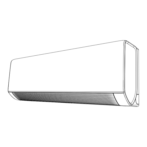
Parts name Indoor unit Air inlet Panel Display Horizontal louver Air outlet Filter Aux.button Outdoor unit Air inlet Handle Air outlet NOTE: Actual product may be different from above graphics,please refer to actual products. -
Page 20: Clean And Maintenance
Clean and maintenance WARNING ■Turn off the air conditioner and disconnect the power before cleaning the air conditioner to avoid electric shock. ■ Do not wash the air conditioner with water to avoid electric shock. ■ Do not use volatile liquid to clean the air conditioner. Clean surface of indoor unit When the surface of indoor unit is dirty, it is recommended to use a soft dry cloth or wet... -
Page 21: Checking Before Use-Season
Clean and maintenance NOTE: environment, clean frequency can be increased. Checking before use-season 1. Check whether air inlets and air outlets are blocked. 2. Check whether air switch, plug and socket are in good condition. 4. Check whether drainage pipe is damaged. Checking after use-season 1. -
Page 22: Malfunction Analysis
Malfunction analysis General phenomenon analysis Please check below items before asking for maintenance. If the malfunction still can't be Phenomenon Check items Solution Whether it's interfered severely Pull out the plug. Reinsert the plug (such as static electricity, stable after about 3min, and then turn on voltage)? the unit again. - Page 23 Malfunction analysis Phenomenon Check items Solution Because indoor air is cooled rapidly. Mist is emitted Indoor temperature and humidity After a while, indoor temperature and from indoor unit’s is high? humidity will be decrease and mist air outlet. will disappear. Temperature can’t be adjusted under Unit is operating under auto auto mode.
-
Page 24: Error Code
Malfunction analysis Error Code When air conditioner status is abnormal, temperature indicator on indoor unit will blink to Note: Above indicator diagram is only for reference. Please refer to actual product for the actual indicator and position. Below listed error codes are only part error codes. Please refero to error code list in serive manual for more information. -
Page 25: Installation Drawing
Installation drawing Space to the wall At least 15cm At least 15cm Space to the wall Drainage pipe... -
Page 26: Installation Prepare
Installation prepare Tools 1 Level meter 2 Screw driver 3 Impact drill 4 Drill head 5 Pipe expander 6 Torque wrench 7 Open-end wrench 8 Pipe cutter 9 Leakage detector 10 Vacuum pump 11 Pressure meter 12 Universal meter 13 Inner hexagon spanner 14 Measuring tape Selection of location Installing the unit in the following places maycause malfunction. -
Page 27: Safety Precaution
Installation prepare Safety precaution 1. Must follow the electric safety regulations when installing the unit. break. 3. Make sure the power supply matches with the requirement of air conditioner. Unstable power supply or incorrect wiring or malfunction. Please install proper power supply cables before using the air conditioner. -
Page 28: Installation Of Indoor Unit
Installation of indoor unit Step 1: Choosing installation location Step 2: Install wall-mounting frame 1. Hang the wall-mounting frame on the wall; adjust it in horizontal position with the level particles in the holes. 3. Fix the wall-mounting frame on the wall with tapping screws (ST4.2X25TA) and then Step 3: Open piping hole 1. - Page 29 Installation of indoor unit order to drain smoothly, slant the piping hole on the wall slightly downward to the outdoor side with the gradient of 5-10°. Note: Indoor Outdoor Pay attention to dust prevention and take relevant safety measures when opening the hole. 5~10°...
- Page 30 Installation of indoor unit Step 6: Install drain hose 1. Connect the drain hose to the outlet pipe of indoor unit. 2. Bind the joint with tape. drain hose drain hose outlet pipe outlet drain hose pipe tape insulating pipe Add insulating pipe in the indoor drain hose in order to prevent condensation.
- Page 31 Installation of indoor unit Step 8: Bind up pipe 1. Bind up the connection pipe, power cord and drain hose with the band. 2. Reserve a certain length of drain hose and power cord for installation when binding them. When binding to a certain degree, separate the indoor power and then separate the drain hose.
-
Page 32: Installation Of Outdoor Unit
Installation of outdoor unit Step 1: Fix the support of outdoor Select it according to the actual installation situation 1. Select installation location according to the house structure. 2. Fix the support of outdoor unit on the selected location with expansion screws. Note: outdoor unit. - Page 33 Installation of outdoor unit Step 4: Connect indoor and outdoor pipe 1. Remove the screw on the right handle of 2. Remove the screw cap of valve and aim outdoor unit and then remove the handle. the pipe joint at the bellmouth of pipe. liquid valve gas valve handle...
- Page 34 Installation of outdoor unit Step 6: Neaten the pipes 1. The pipes should be placed along the wall, bent reasonably and hidden possibly. Min.semidiameter of bending the pipe is 10cm. 2. If the outdoor unit is higher than the wall hole, you must set a U-shaped curve in the pipe before pipe goes into the room, in order to prevent rain wall...
-
Page 35: Step 7: Vacuum Pumping
Installation of outdoor unit Step 7: Vacuum pumping Use vacuum pump liquid valve piezometer 1. Remove the valve caps on the liquid valve gas valve and gas valve and the nut of refrigerant refrigerant valve cap charging vent. charging vent 2. -
Page 36: Check After Installation
Check after installation Items to be checked Possible malfunction The unit may drop, shake or emit noise. Have you done the refrigerant leakage test? capacity. It may cause condensation and water dripping. Is water drained well? It may cause condensation and water dripping. Is the voltage of power supply according to the voltage marked on the It may cause malfunction or damaging the parts. - Page 37 1. Standard length of connection pipe 2. Min. length of connection pipe is 3m. 3. Max. length of connection pipe and max. high difference. Max length Max length Cooling Max height Cooling Max height of connection of connection capacity difference capacity difference pipe...
-
Page 38: Pipe Expanding Method
Pipe expanding method Improper pipe expanding is the main cause of refrigerant leakage. Please expand the pipe according to the following steps: A: Cut the pipe E: Expand the port Expand the port with expander. distance of indoor unit and outdoor unit. Cut the required pipe with pipe cutter. -
Page 39: Instrukcja Użytkownika
INSTRUKCJA UŻYTKOWNIKA Klimatyzator z systemem split NORDIC SENSEI SAC-09SKWN/I SENSEI SAC-12SKWN/I Dziękujemy za wybranie naszych produktów. Aby zapewnić prawidłowe działanie, należy uważnie przeczytać i zachować niniejszą instrukcję. ENG LISH PO LSKI УКР А ЇНСЬКА W W W.S ENSEI -EURO PE.COM... - Page 40 ....................1 Pilot........................11 ..............16 ................17 ....................19 ..................22 ................23 ................25 ................29 ..................33 ..................33 ..................34 ..................35...
- Page 41 UWAGA...
- Page 42 UWAGA...
- Page 43 UWAGA...
- Page 44 UWAGA...
- Page 45 UWAGA UWAGA!
- Page 46 UWAGA...
- Page 47 UWAGA...
- Page 48 UWAGA...
- Page 49 UWAGA...
- Page 50 UWAGA...
- Page 51 Pilot wentylatora temperatury Funkcja Sen zasilania przycisk przycisk Przycisk ustawiania wentylatora Przycisk Przycisk Przycisk ustawiania Przycisk timera Przycisk Przycisk...
- Page 54 Funkcja wachlowania Przytrzymaj przycisk, Funkcja Funkcja wachlowania wachlowania...
- Page 56 Panel powietrza Filtr Przycisk AUX powietrza powietrza Uchwyt...
- Page 57 UWAGA! ■ ■ ■...
- Page 58 • • •...
- Page 59 Czy pilot jest skierowany na Czy w pomieszczeniu jest Powietrze nie Klimatyzator...
- Page 60 Czy w pomieszczeniu jest emitowana z Temperatura Zakres temperatur Czy ustawiona temperatura...
- Page 64 Klimatyzator 、 、...
- Page 65 Poziom po lewej stronie Tylny otwór na rury Tylny otwór na rury...
- Page 66 w prawo rura klucz z otwartymi ustami rura cznikiem momentu rura izolacyjna...
- Page 67 rura rura izolacyjna DO WYBORU DO WYBORU SENSOR SENSOR CZUJNIK CZUJNIK TEMPERATURY TEMPERATURY POKOJOWEJ RURKI Panel NIEBIESKI NIEBIESKI TEMPERATURA czarny PAROWNIK KROKOWY KROKOWY DO WYBORU DO WYBORU DO WYBORU...
- Page 68 Rura spustowy Uzwojenie Rura Rura cieczowa Uzwojenie uszczelniacz...
- Page 70 zawór cieczowy zawór uchwyt DO WYBORU DO WYBORU CZUJNIK TEMPERATURY CZUJNIK CZUJNIK NAGRZEWNICA NAGRZEWNICA RURY TEMPERATURY czarny REAKTOR DO WYBORU DO WYBORU DO WYBORU...
- Page 71 litery U...
- Page 72 spanner...
- Page 73 Czy izolacja termiczna Czy wloty i wyloty powietrza...
- Page 74 rury...
- Page 75 Rozszerz otwór rury za prasa rura rura nierównie Rura rury równa powierzchnia powierzchnia nierówna pochyleniem rurowe rura...
- Page 76 WWW.SENSEI-EUROPE.COM INFO@SENSEI-EUROPE.COM N081102-000059-002...
- Page 77 ІНСТРУКЦІЯ КОРИСТУВАЧА Кондиціонер Спліт Система NORDIC SENSEI SAC-09SKWN/I SENSEI SAC-12SKWN/I Дякуємо за вибір нашої продукції. Для належної експлуатації уважно прочитайте та зберігайте цю інструкцію. ENG LISH PO LSKI УКР А ЇНСЬКА W W W.S ENSEI-E UROPE. COM INFO@SENSEI-EUROPE.COM...
- Page 78 ....................1 ..............11 ...............16 ................17 ..................19 ...................22 ..................23 ................25 ................29 ...............33 ....................33 ................34 ..................35...
- Page 95 ■ ■ ■...
- Page 102 、 、...
- Page 114 WWW.SENSEI-EUROPE.COM INFO@SENSEI-EUROPE.COM N081102-000059-002...
Need help?
Do you have a question about the NORDIC SAC-09SKWN/I and is the answer not in the manual?
Questions and answers